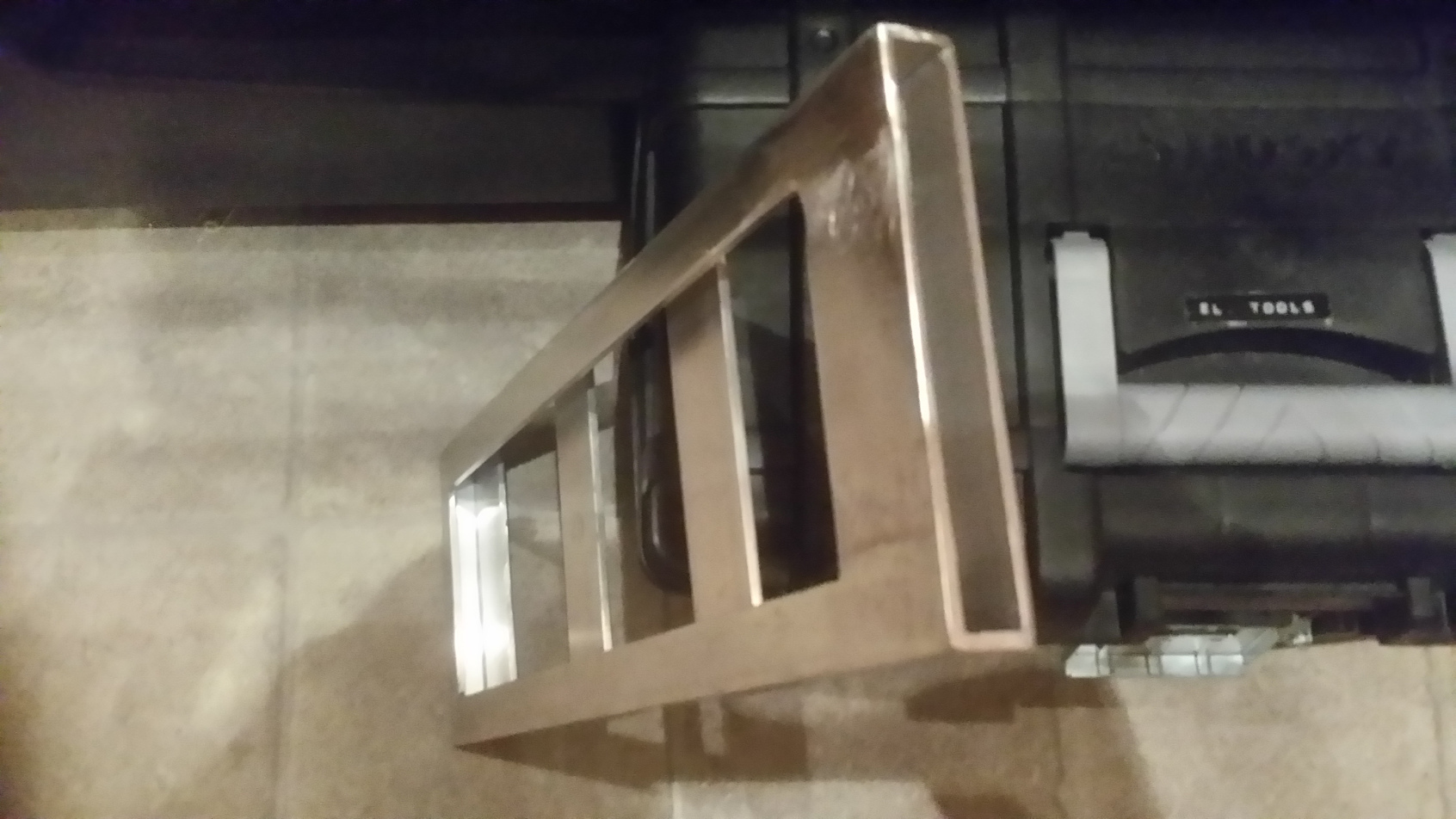
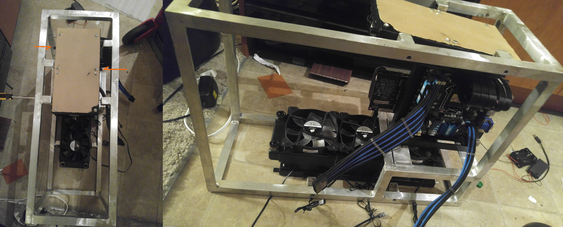
So last time I had some welding done, I did both the PSU mount and the start of the motherboard tray. Since then I added threaded rivets for screwing in the motherboard and had right angle bars welded to the back and bottom for attaching and rigidity.
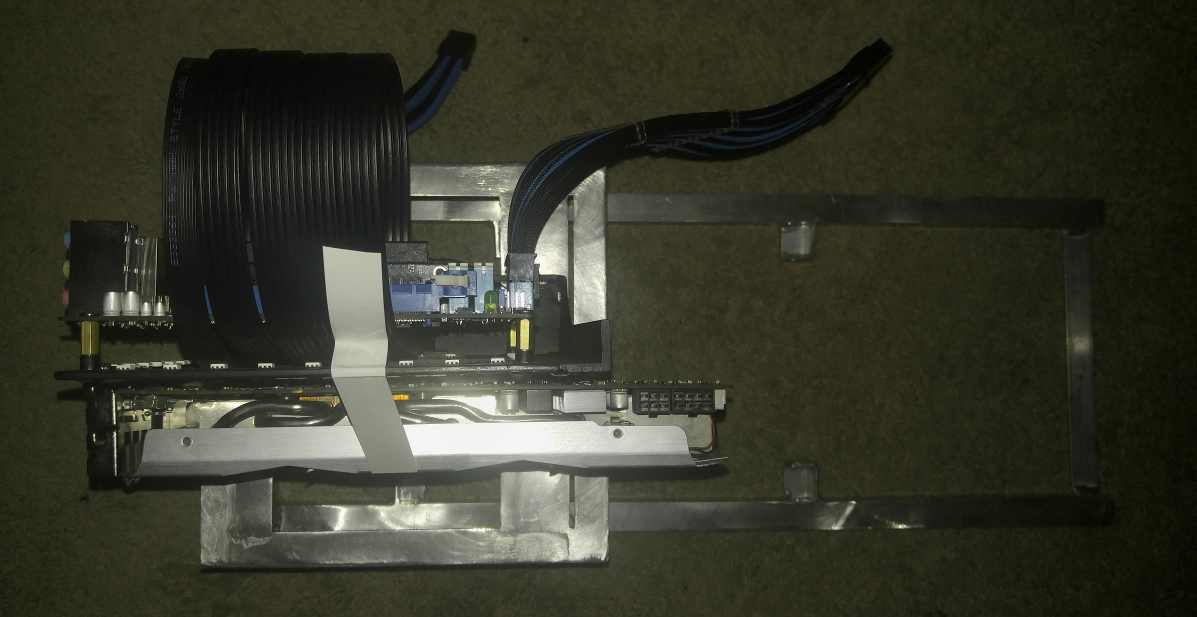
Unfortunately the DEEP COOL PCI-E extension cable didn't really work, so I ended up going with the Lian-Li extension cabe and that one mounts to the base rather than the wall. So now I have to find a work around to screwing it to the tray.
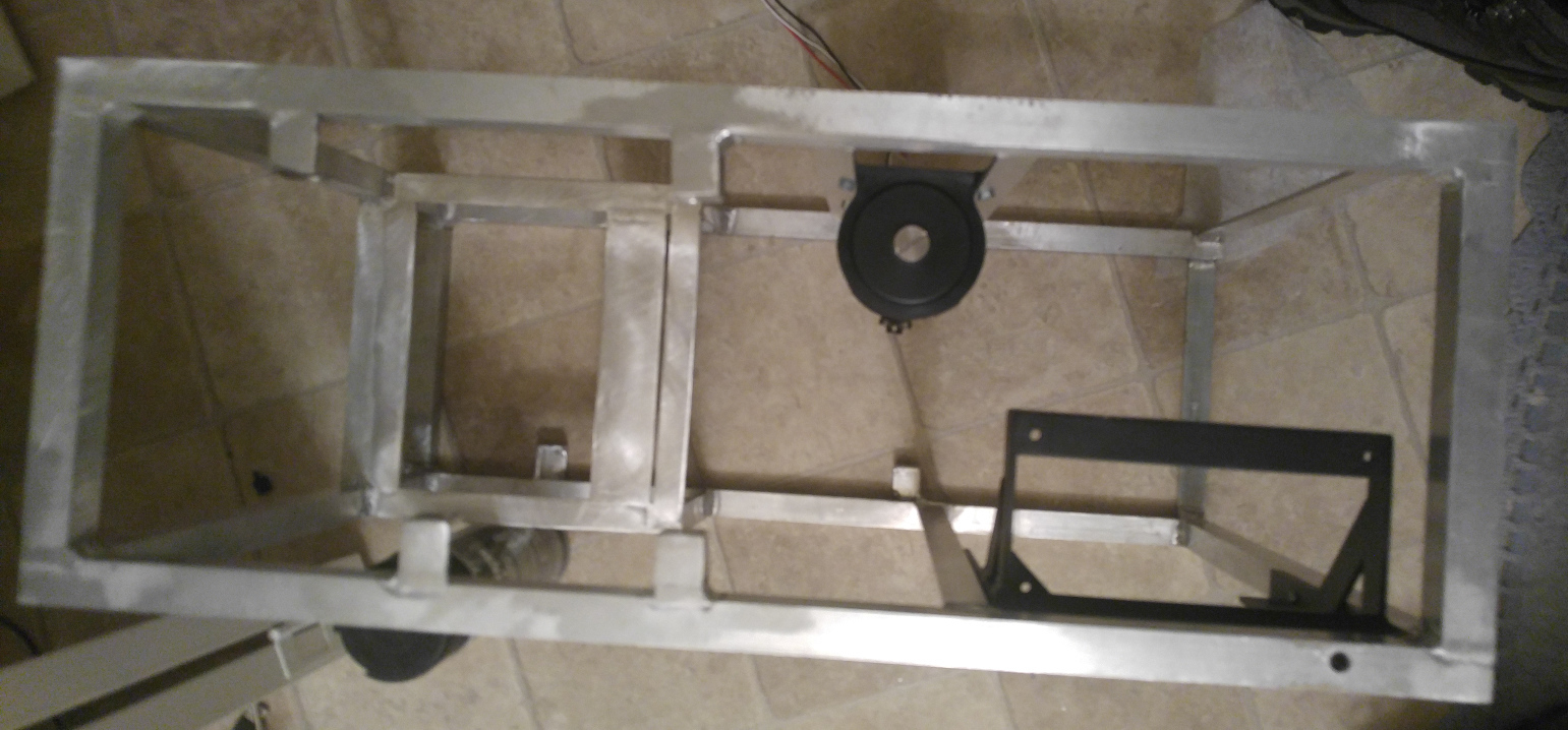
So it looks like Lian-Li PW-PCI-E38-1 is stable. So far I've cut the opening and cut the mounting brackets. Now I just need to weld those on.
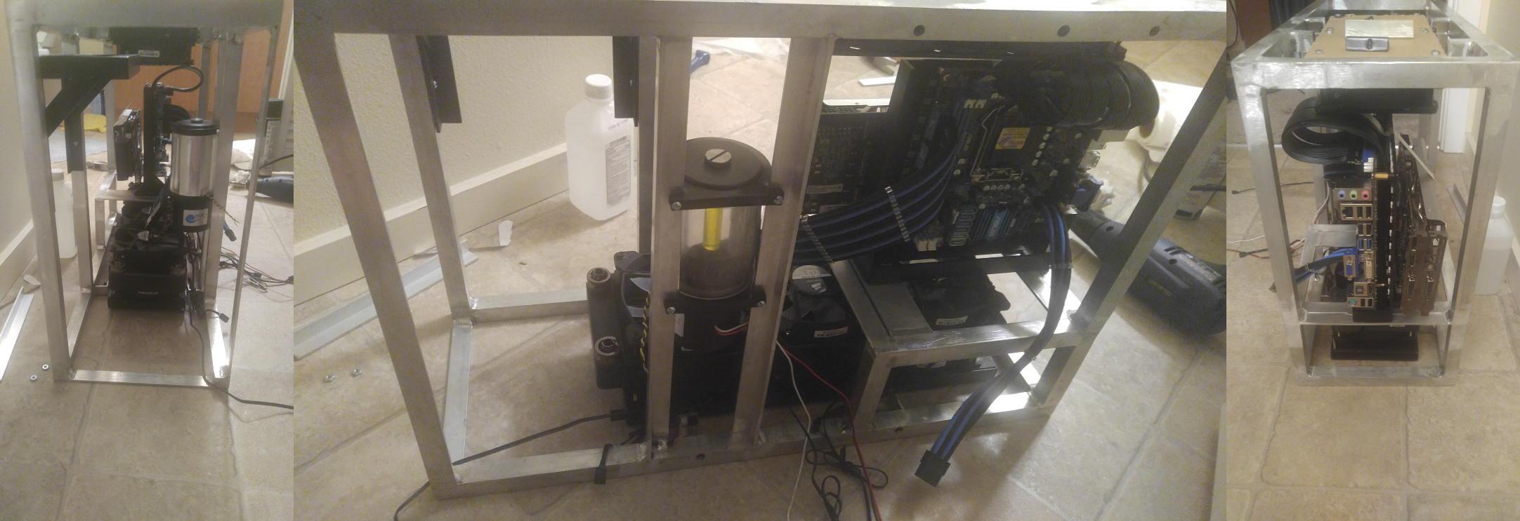
So thing kind ended up coming to a halt as I don't know if I'm going to be moving in a few months and a few design snags came up. Right now I don't know if I'm going to keep with the dual loop peltier design or not as it makes it taller than planned. So as of now I have all the parts I made painted (PSU mount, vents, MB tray). Eventually all these will be riveted to the main body frame.
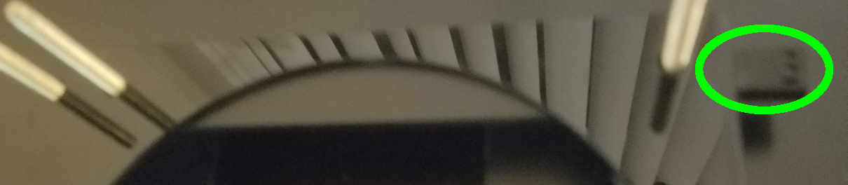
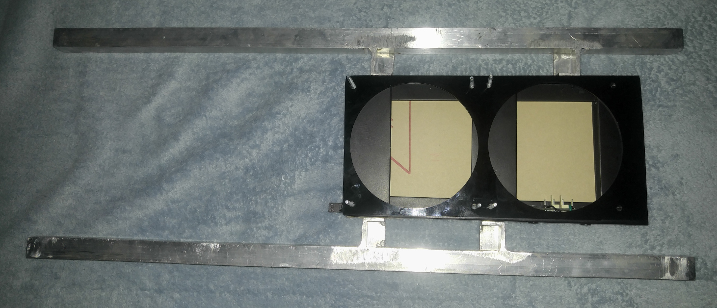
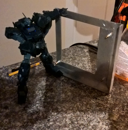
Also... the smaller one is an outlet while the longer one is the inlet. And if you're wondering, it won't be exposed, the top and bottom will have an acrylic cover.
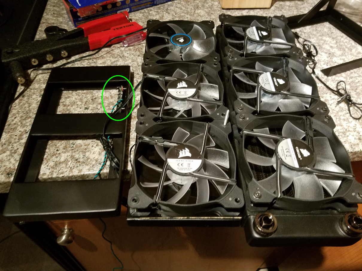
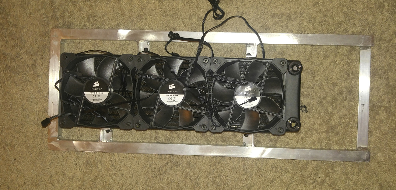
So to recap where I left off: I finished the vents including the wiring for the fans. The idea behind these vents is that you wire up all the fans within the vent with one connector going out to control them all.
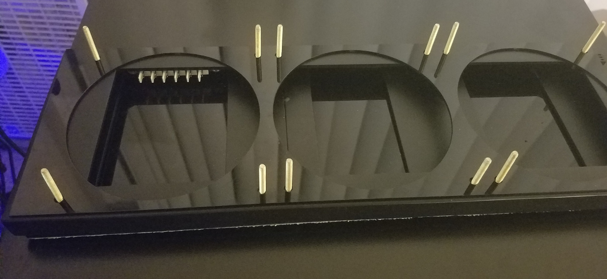
Initially my plan was to have these vents riveted in, but that introduced a few snags. For one, installing radiators would become a royal pain and it would have added an inch on each side. My solution to this problem was to just have them screwed in and have threaded rivets in the vent. So I've started on the attachment points (4 per vent).
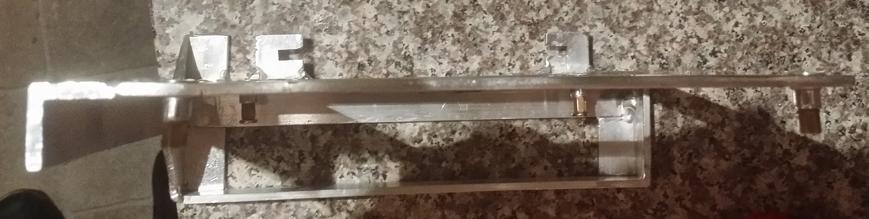
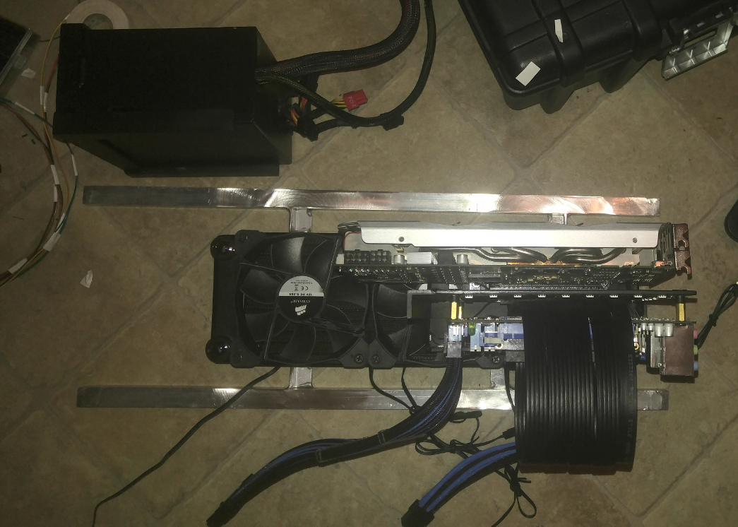
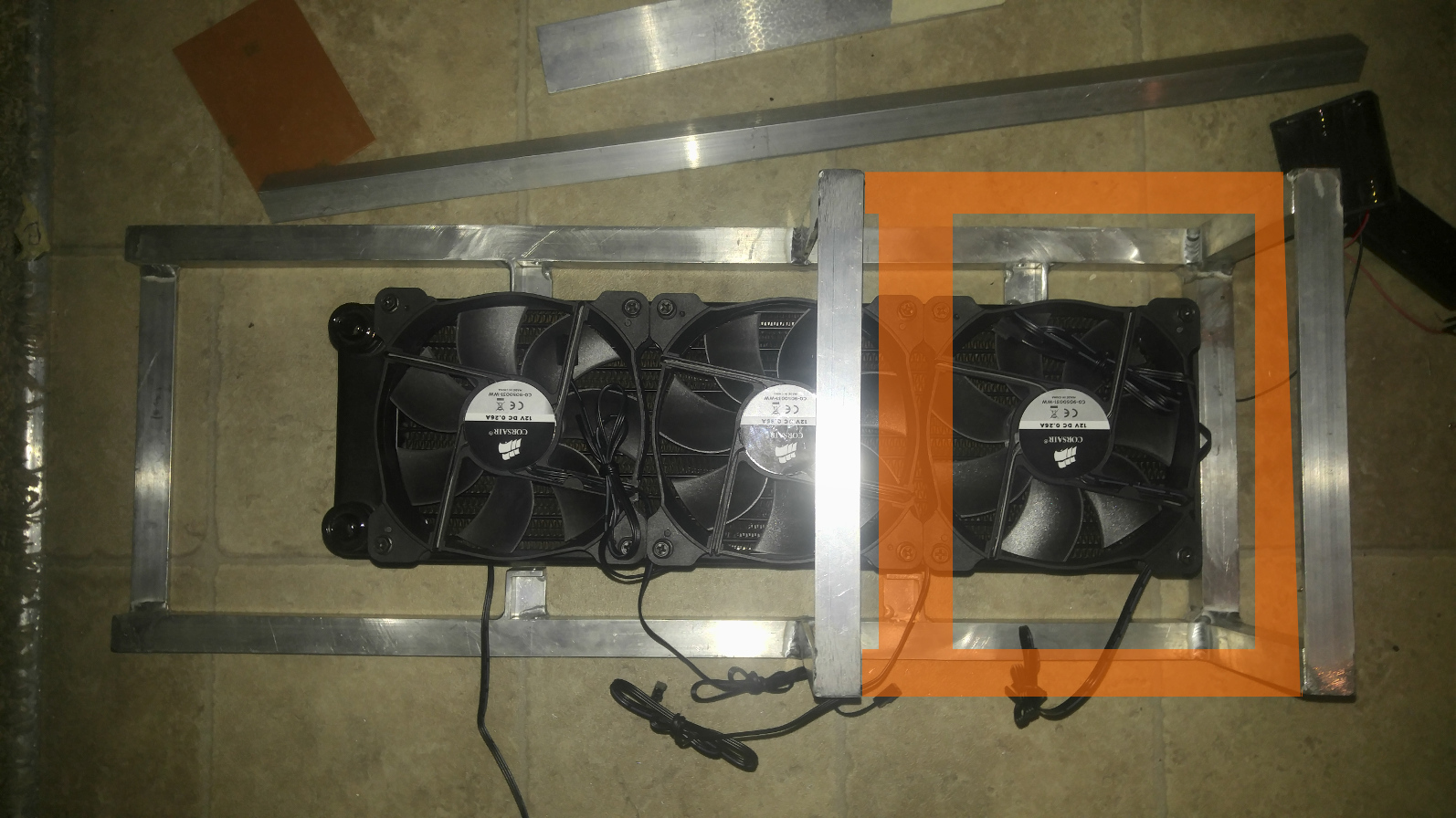
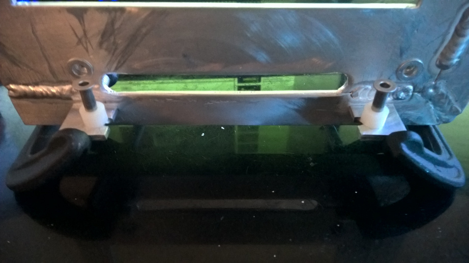
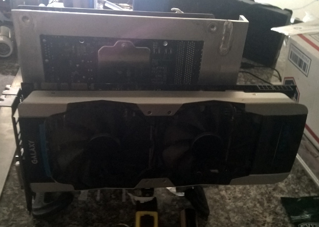
Got the bottom mounting points welded on. I'll be joining the two bars to make the base tomorrow. Below I have the radiator screwed onto the vent with the MB tray sitting on top. The tray will be about 4 to 5 inches above floor after I build up the base. The nice thing is the cool air will blow across the entire MB/ GPU with this design.
It'll be a bit of time till the next update as I'll need to figure out how to work out the mid section of the case. Also I need to create the stepped vent connector so the intake and outtake vents vent air from outside. Right now their path is obstructed by the square bar in the back.
Yay, more progress on the mid-section. In orange is where some more bars are going be welded onto. They'll be the spots where the mother board tray will sit on. After this it's the to top half, the 4 corner columns that join the top and bottom followed by an assort of columns for mounting things like the drive bays and pump.
As you can see the last fan blows across both the MB and GPU with the middle reaching the end of the GPU.
FYI, I'm going to opt to stick to the carry-on size, so the second loop and peltier aren't going to make it in (* may be one end of the peltier for future changes).
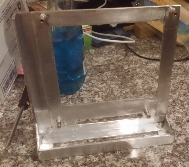
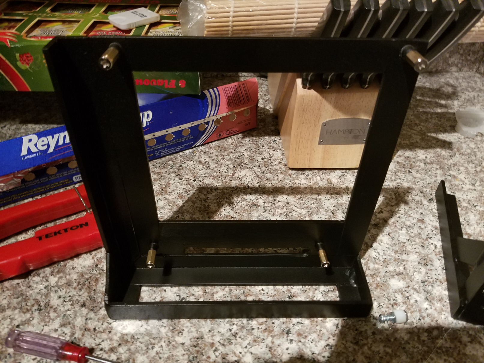
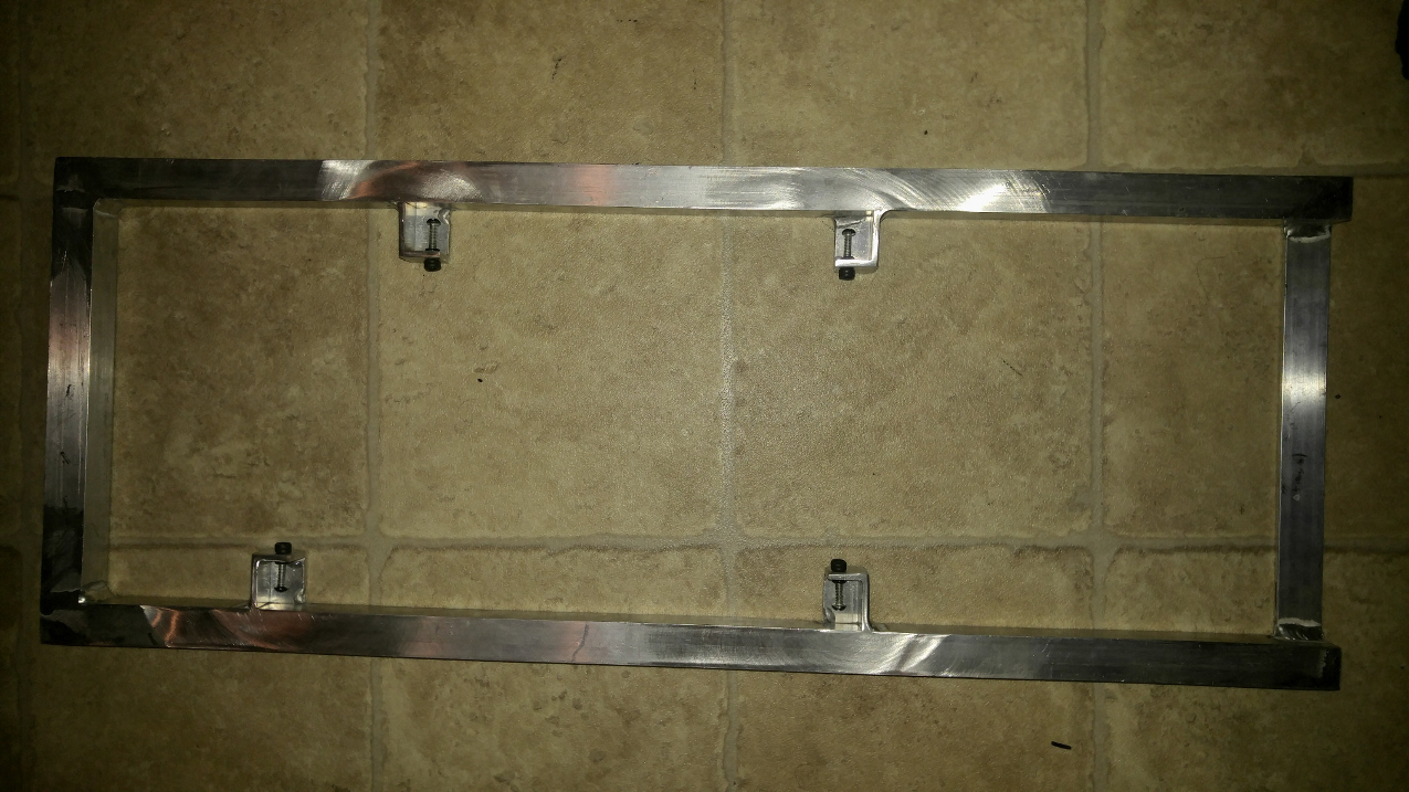
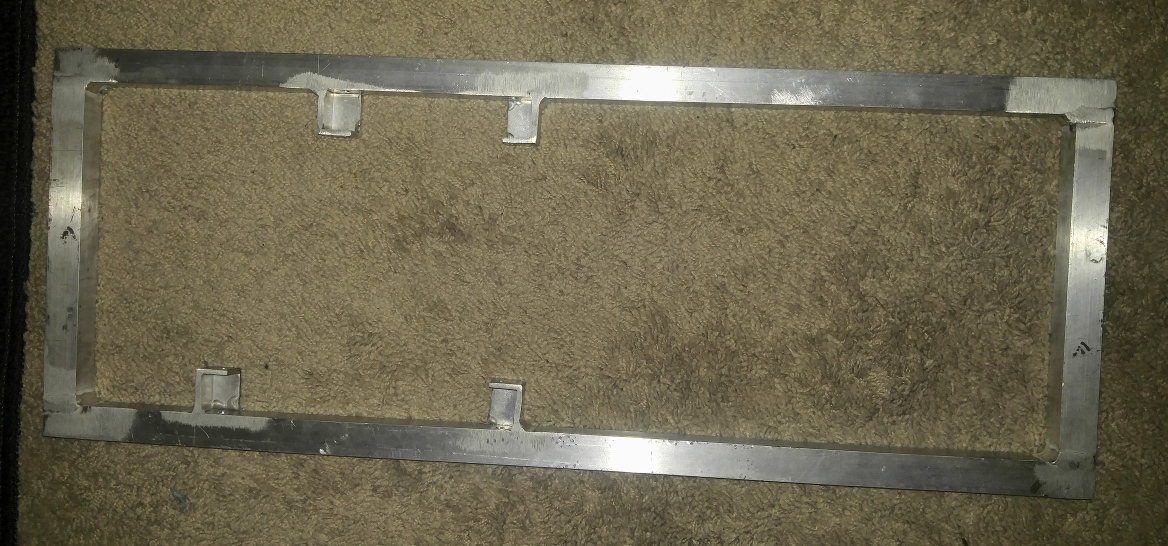
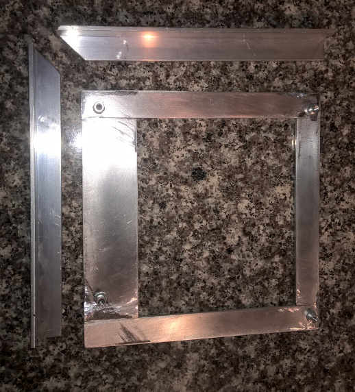
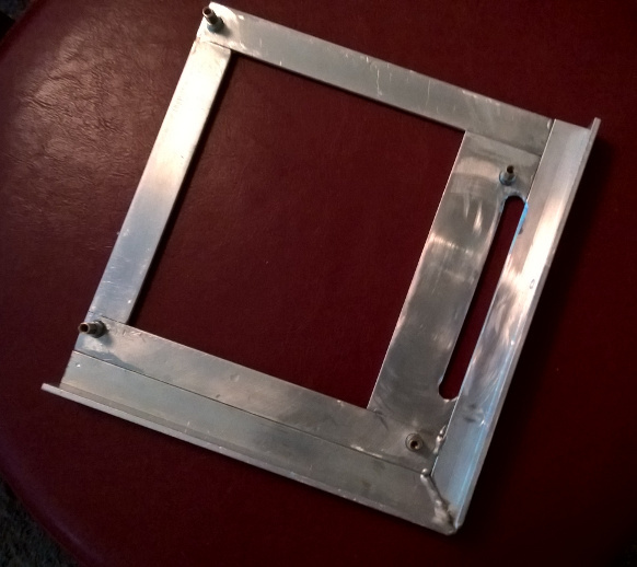
Woo Hooo! the outer frame is complete! However... I did screw up 2 of the screw mounts (see photo). So... time to pull out the saw and cut some segments off. Next up, joining the PSU mount!
Next up will be the mounting bracket for the GPU and the mounting bar for the 6 4" drive bays. Once the 6 drive bays go in, this case will be pretty packed.
 .
.