Wish I had a fry's close by, love that store.
So pretty much I'm looking in the right place then, thanks for the reply
Wish I had a fry's close by, love that store.
So pretty much I'm looking in the right place then, thanks for the reply
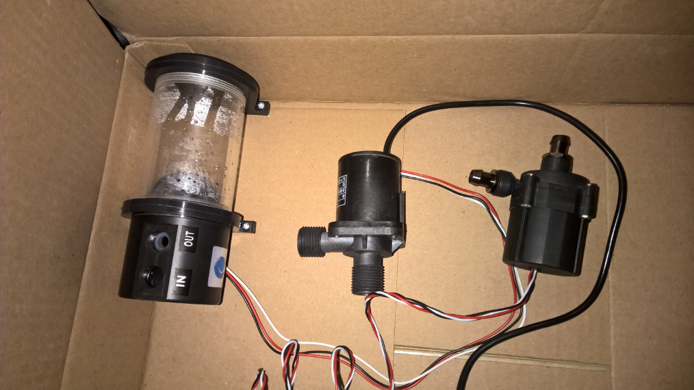
So building the CPU water block is going to be a layered process that'll eventually end with joining a top and bottom half. Right now I have the base made with a 1/4" acrylic square screwed to the copper plate. Also, after trying out a bunch of pumps, I settled for a $30 reservoir, pump combo that's way more quiet than the other two I tried. So there will be 2 of these (1 hot loop, 1 cold loop).
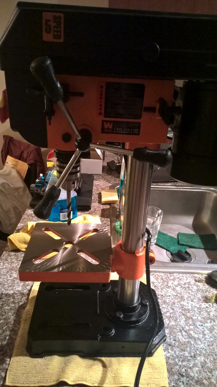
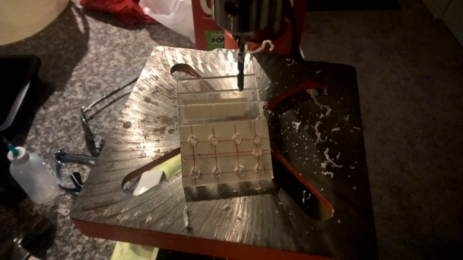
There's something satisfying when you hear a loud thud on the front door and you know exactly what it is. Got the drill press to route the holes for the cpu block.
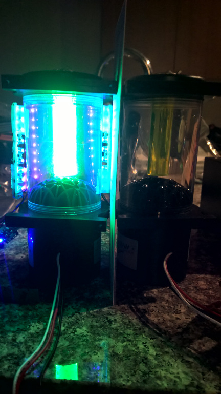
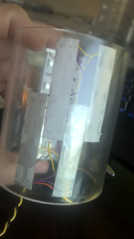
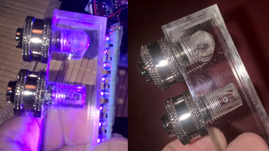
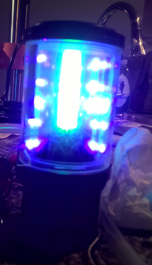
Just added UV led strips to the reservoir. I used a 2.5" ID acrylic cylinder to sandwich the LEDs in-between. I also added aluminum foil tape to give it a more uniform look and hide the back of the LED strips.
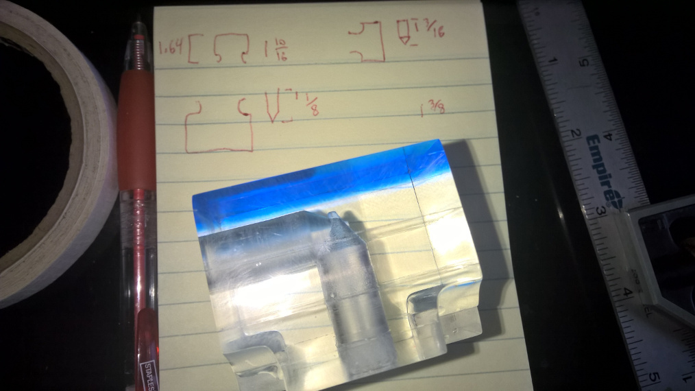
I still haven't gotten to the mounting holes, but I got the vertical column almost done.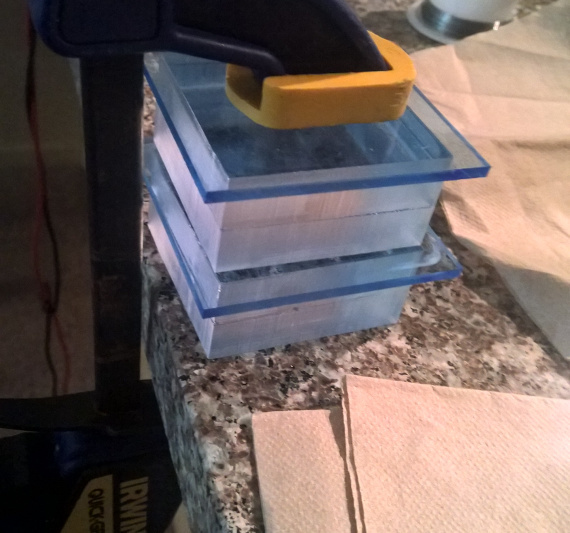
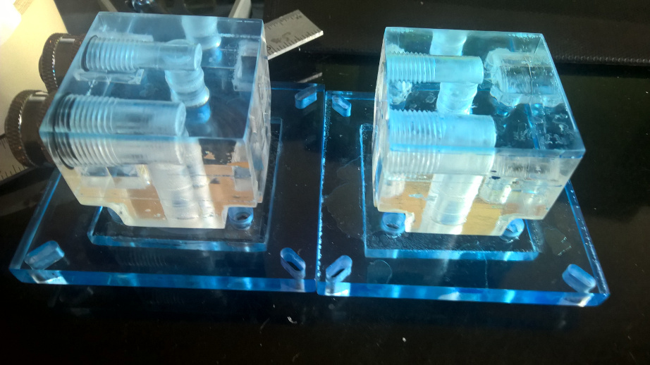
So I finished the lighting for both reservoirs. I'll eventually include a photo of both lit after I build control circuitry.
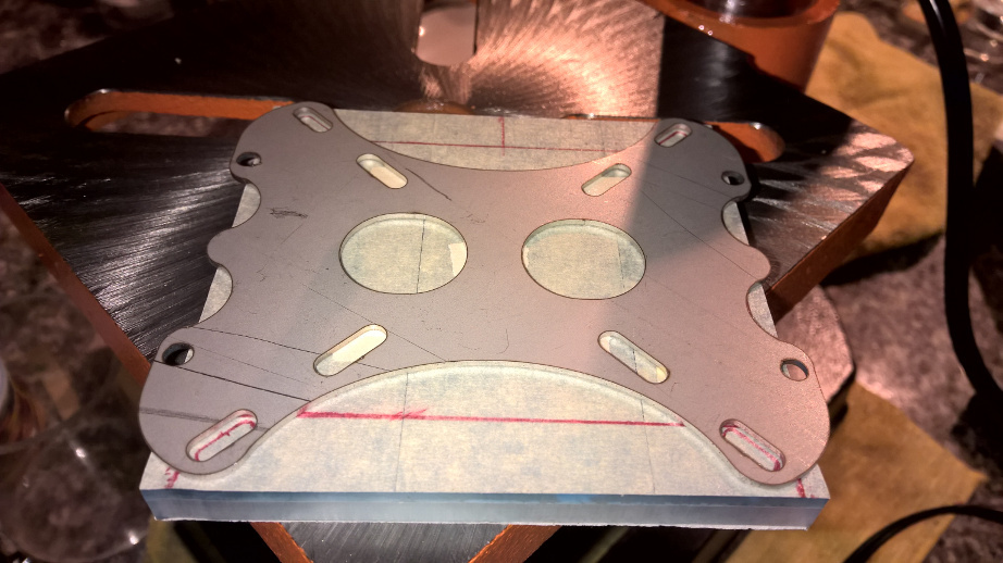
I also drilled the mounting holes and glued the final layer to the vertical column. I'll show more on the vertical column on another day. So to produce an accurate slit for the mounting holes, I first dill pressed as much out of the open space (starting from the far ends of the slit) and then with the metal bracket as a guide, routed the open space to produce a uniform slit. As you can see in the bottom photo, one edge is a bit close to the power, so I'm going to have to send the base to get edge routed by 1/8".
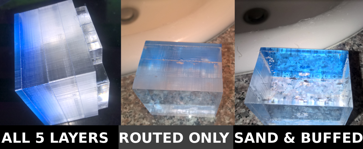
So producing the top of the water block was a layered process starting with the second to the top layer. I couldn't just do one large block as 1/2" was reaching the limit of what the router could handle with such a small area. In terms of thicknesses from top to bottom, it goes: 1/8",1/2",1/2",3/8'",1/4". I actually miscalculated the clearance for the screw and should have swapped the last two. Building up the layer was a matter of starting with a routed piece, gluing an un-routed piece with a thick out lip and then routing that lip off and repeating that process. As for gluing the layers, I use the flood technique with acrylic cement. Using the capillary effect wouldn't work as I need entire area glued and not just the edges.
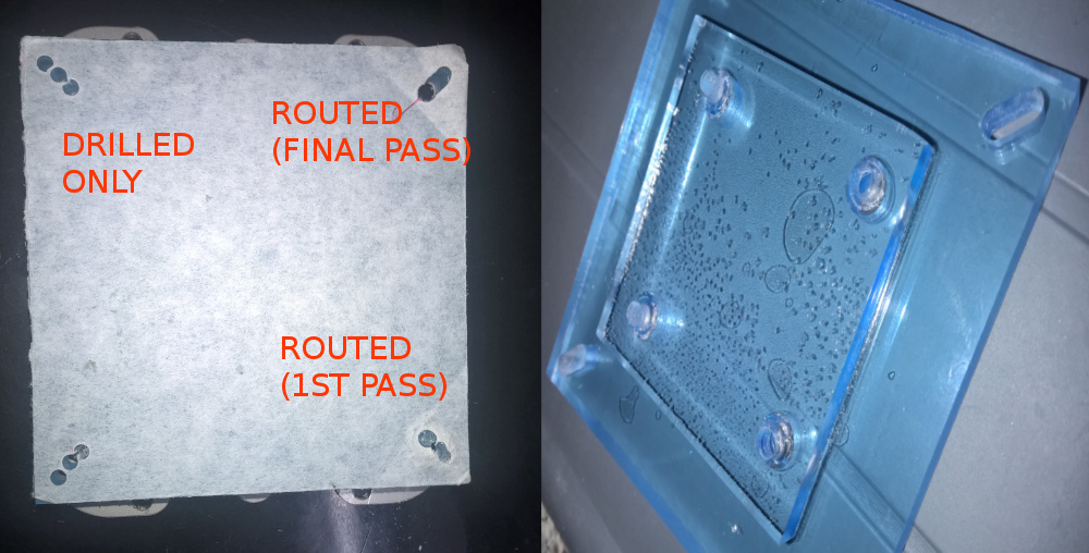
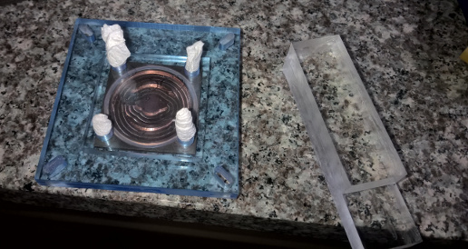
Here's a more detailed look at routing the base plate. On a side note, this is a dremel routing bit and not the same as used for the top portion. Update: I also glue the base plate top to it too. I was a little slow while joining the two so you'll notice a bunch of tiny glue bubbles formed (needed the holes to match).
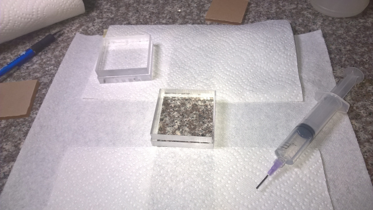
 ...and like last time, place paper napkins to avoid spill over.
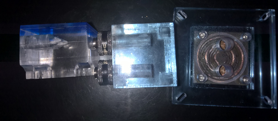
Here's both parts stacked (not glued). If you look at the left corner, you'll see I had to use a small sanding drum to widen the gap for the screw to fall in for the copper plate.
That is amazing but not entirely sure where the water passes through to to copper, may just be i am tired, will check it again in the morning
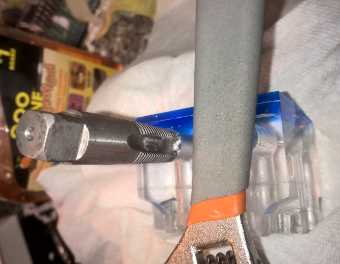
I have two 7/16" drill bits and I'm still grinding one of them to a flat so I can make a nice 90 degree turn when I drill in from both ends. That's the 2nd to last step for the water block.
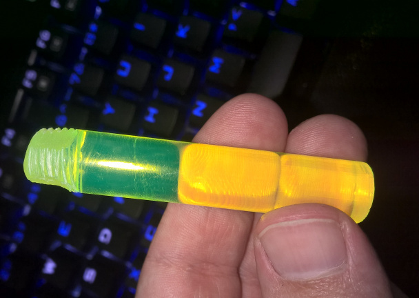
Update: Tested out the flat drill bit. First you have to start off with a regular acrylic drill bit before flattening out the tip of the hole. Also you need to keep the hole lubricated well (I use goo-gone, has a nice lemon smell to it). As for threading, as long as I have 5/8" depth, the threading tool will widen the hole enough for most fittings.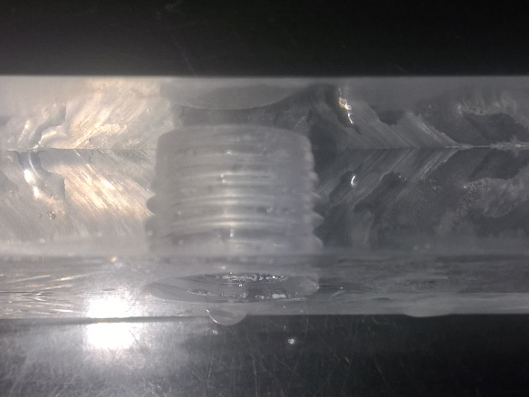
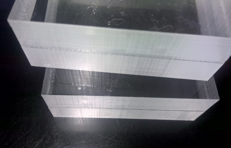
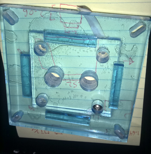
Just tested a 90 deg. hole with some scrap acrylic to test drilling at a glue seem and which drill style to go with (continue hole from vertical or horizontal end). I'm going with continuing the hole from the horizontal; the flat circle still looks a bit rough despite lubricating the hole.
oh I see, cant wait to see more.
As I mentioned before, first I use the acrylic drill bit to make the pathway before continuing with the flattened drill head. In this case with horizontal path going all the way, although you'll notice I went a little too far with the flat head on the vertical on one of the two path ways. I also drilled the pathway for the base plate. Next up will be joining the two.
Just worked on the backup block. Going to start with the backup block when joining the two halves. The primary looks a lot better, so I may as well make mistakes on the secondary first.
Update: both are a succes; joined and tested for leaks ^_^.
 .
.
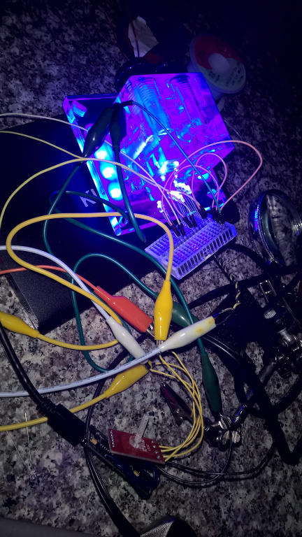
Lighting test:
Update: been out of town, but I got the water block finished before leaving. Tested the circuit, drilled the LED holes, and built the enclosure. For Drilling the holes, I double stick-taped some acrylic blocks in a step pattern to get the angle (had to slowly sink the drill to stay in place).
The PWM motor break out board I used was designed for a slower clock speed so I had to do some research on how to slow down the Arduino PWM. As for the enclosure, I used a 1/2" thick black acrylic block to build the section for the arduino / pwm board. To make the open space, I used a large drill to first gut it and then routed it to a square opening. For now I don't have photos of it, but I'll include photos of the finished product later.
How goes the build? Looking forward to the progress.
Moving along, but going to be side tracked every here and there with work, vacation and job hunting. Eventually I'll show the final results of the water block when I get back.
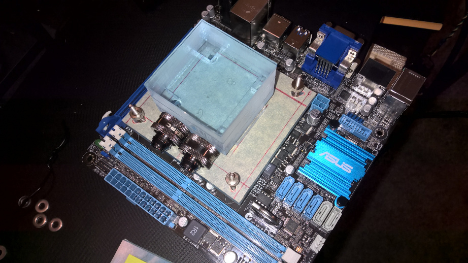
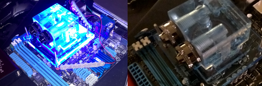
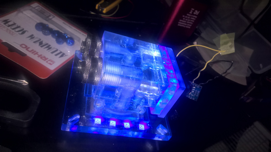
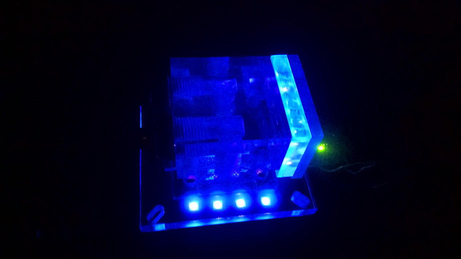
Update: Here's the final result of the CPU water block with the 5/8" (1/2" mid section + 1/8" back wall) black enclosure for the arduino.
Man that looks really nice
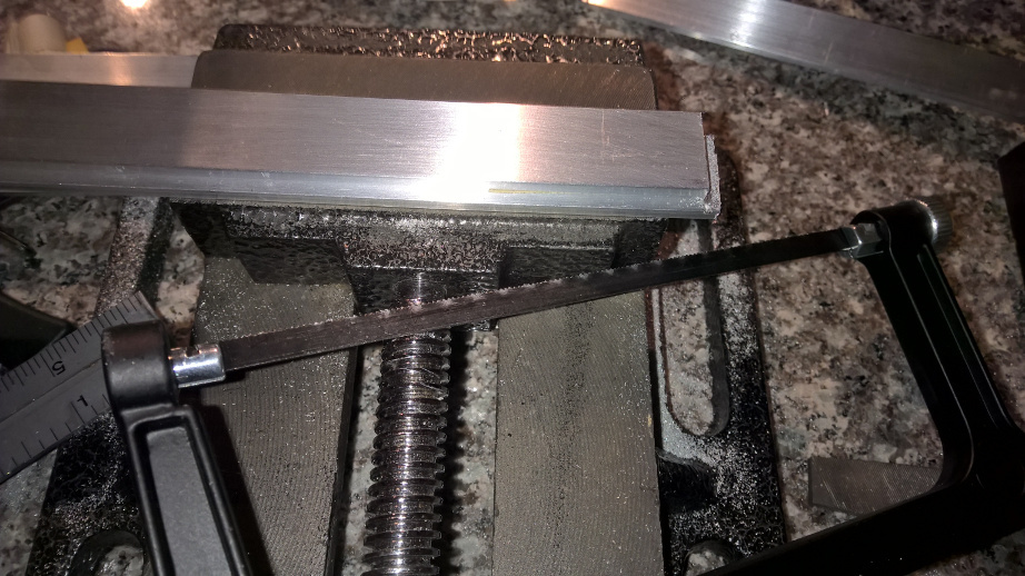
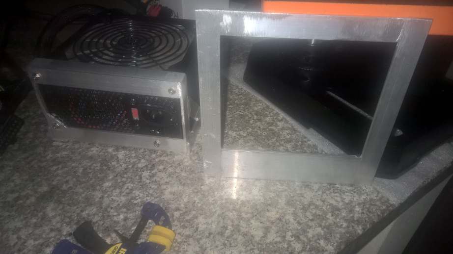
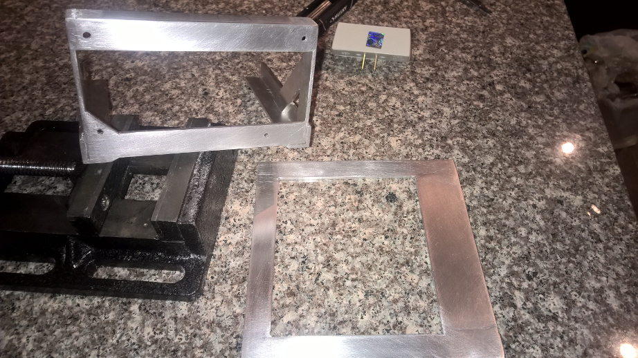
Just cut the aluminum to produce the mounting bracket (still need to finish the 45 degree cuts) . A little tip to getting consistent cuts; just stack the finished one on top and guide the saw blade along side. I'll also probably start work on testing the water block in MM 1.2 soon. Next up will be TIG welding the bars together of the mounting bracket.
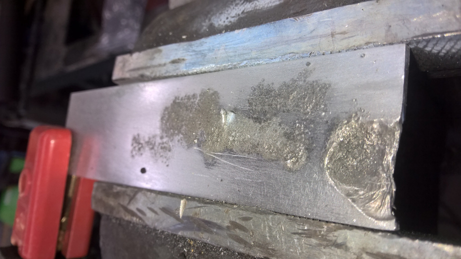
Update: The alternate plan worked out, although I didn't notice one of the holes was above the bracket. So tomorrow I'll have that small triangle welded in for that 4th screw hole. TIP: unlike acrylic where if you make a cut in the wrong spot, you can fill in gaps with minimal to no cosmetic damage. Also for a strong bond (especially if you're grinding the weld to a flat), grind the edges to produce a groove between joints for the weld to go deeper. ANOTHER UPDATE: just had that corner welded (and the motherboard tray) and now I have all 4 screws in... Next up is testing parts in MM1.2 and sanding those aluminum parts to a smooth surface.
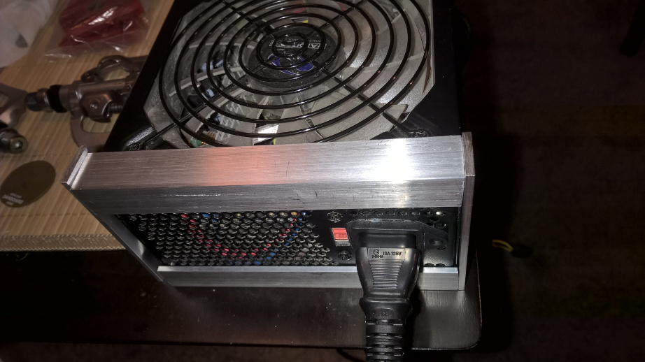
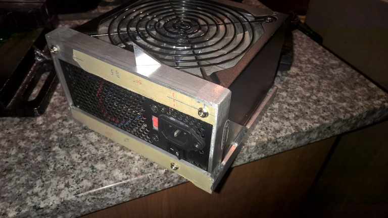
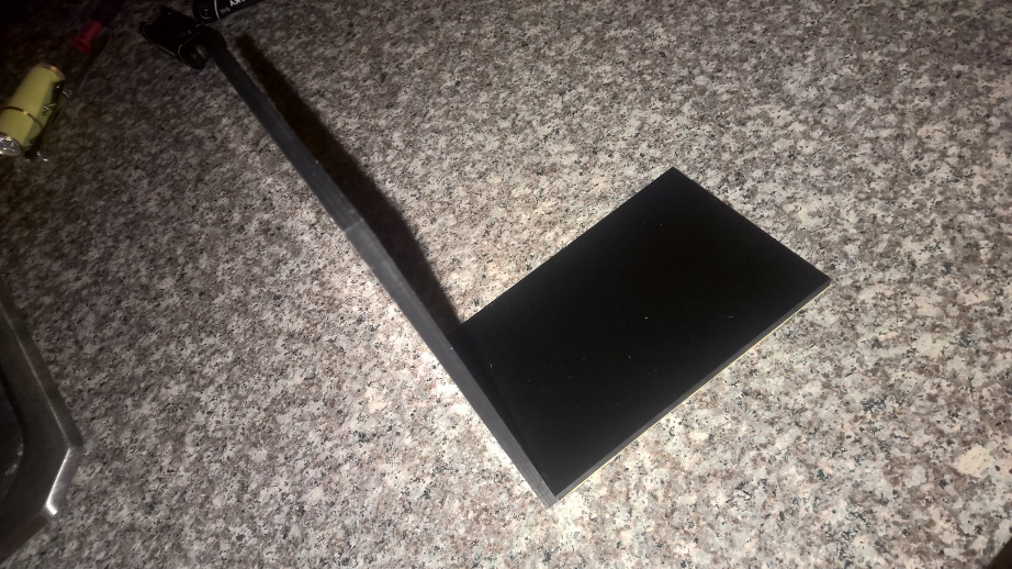
So I've gotten the frames sanded down as far as I could, although there's still a few deep scratches from the grinder belt. It won't matter much after I spray it down with a flat black. So now it's onto testing the water block and pci-e 16x extension cable. I've built a bracket to hold the GPU when I put in the cable.
Just revised the starting post. Initially I was going to break down the test in MM 1.2 into two stages, but now I'm going to just do the second half in the aluminum frame.... probably going to be offline for bit.
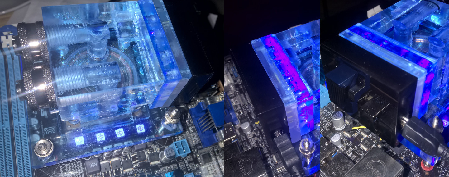
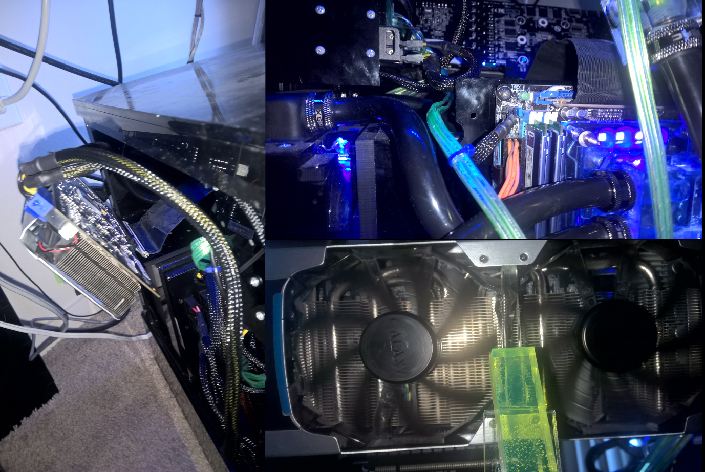
So the test was a success. The PCI-e extender cable worked and no leaks from the new water block. If you're wondering how I have the GPU angled that way, you'll notice a clear acrylic bar wedged right between the two fans, just between the fan shields and metal cover.
Just joined the top section of the blocks... this is pretty much the same process as the CPU block... just not as tall.
Great stuff Mr_UNOwen.
Seriously wish I had enough time to do this much custom work.
Keep it up!
Really look forward to seeing the final product.
At this point I'm just testing my job to see how long I can do this before either my contract ends or I'm prematurely booted. My career has been in a nose dive after getting let go from my full time job, so this is just me giving NO F####s till I get an actual decent full time job. Well... technically this and interview prep to land a full time job.
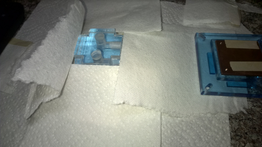
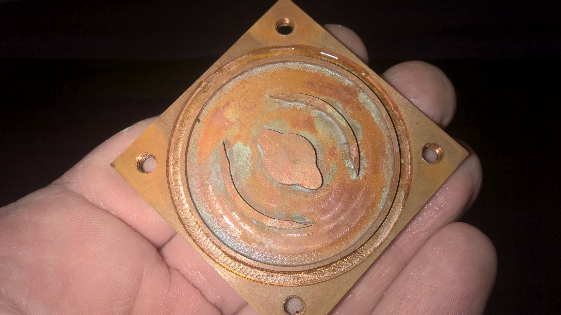
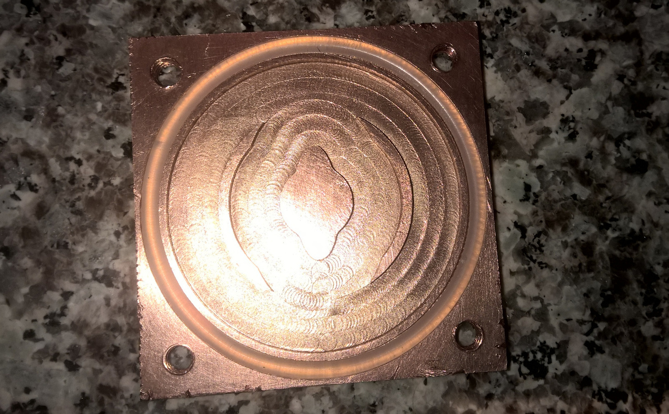
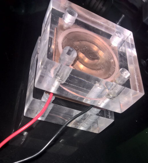
So building the peltier heat exchange blocks is pretty much the same process as the CPU blocks except for a few drill holes and some threaded rivets for joining and mounting the two halves. Unlike the cpu block where I had 1/4" thick piece for neck screw to go through and the rest of the block to create the wider hole; this time I had to drill the larger hole on top while making sure I don't go too deep. So here's the blocks routed, with copper plate holes and finally with the water pathways with fitting threads.
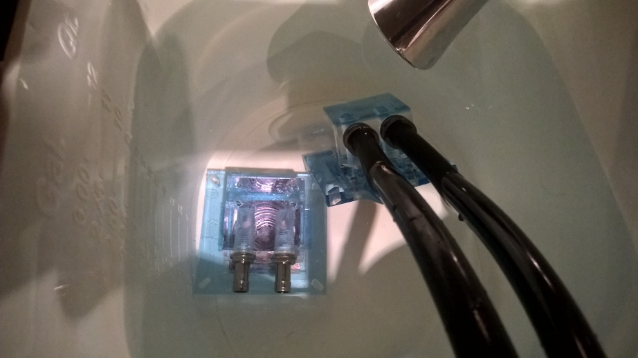
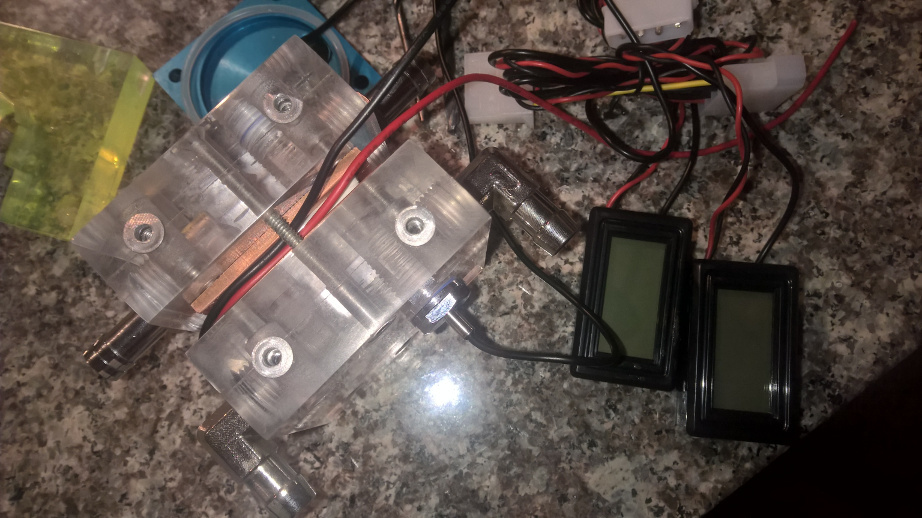
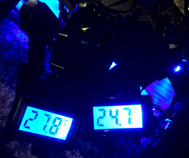
You'll notice there's a third hole with a temperature probe in it. I'll be testing the blocks with a simple loop with each going to and from a pump-reservoir combo. I'll be checking to see which side is the cold end and how hot the other side can get before it overwhelms the cold side (or just gets cold enough that I'm satisfied).
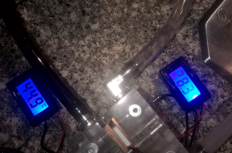
So the test performed as I expected, however I had to end it prematurely as the hot side leaked due to 2 of the screw holes holding the copper base were stripped. I have another copper base coming in a week or two, so I'll just cross this part off the list of things to complete since I got the results I wanted to see. Below is the change in temp over 10 minutes.
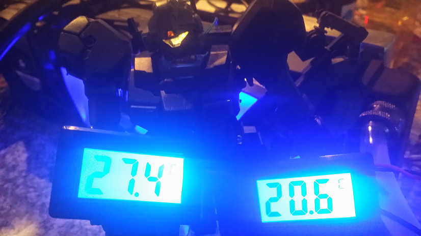
Update: replaced the bad copper base/seal and now the leaking is gone. However looks like one of the wires broke off the peltier so now I need to replace that part. Although I did get some good readings (note: this time I have the hot end hooked up to a radiator).
Update #2: got it all fixed up and now it's down to 20c.
 .
.