The fan can actually hold the filters stacked against it’s inlet when running full tilt. So having double the area was a good decision.
Edit 2:
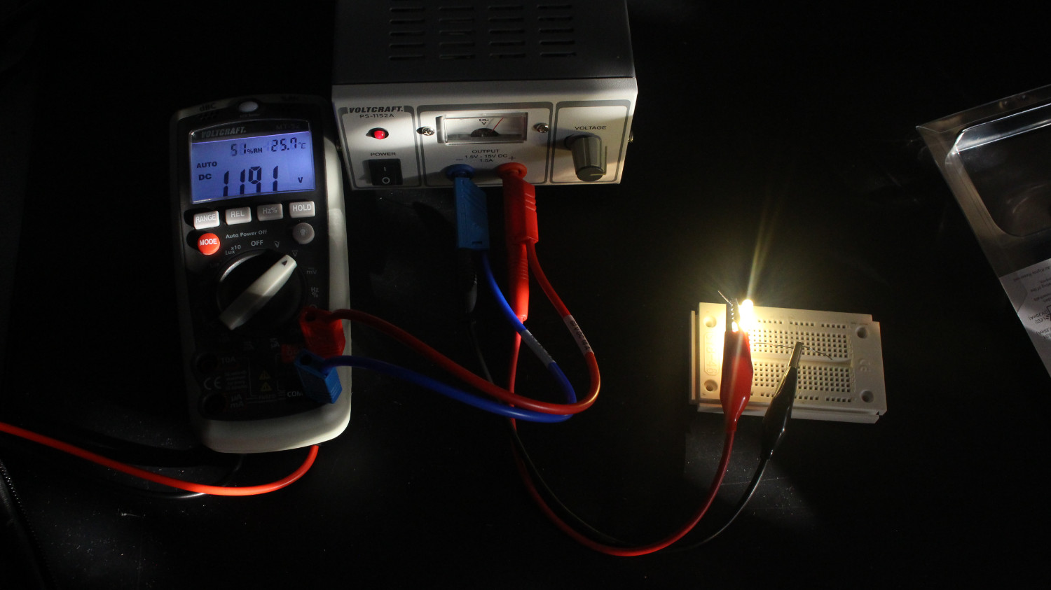
Took some measurements:
Resistor gets to 40-ish °C during extended operation. “Low” mode is 4W to the fan, “high” is the full 10W (or 9.6 as measured).
Works amazingly well for solder fume remover, also works to circulate some air through the room.
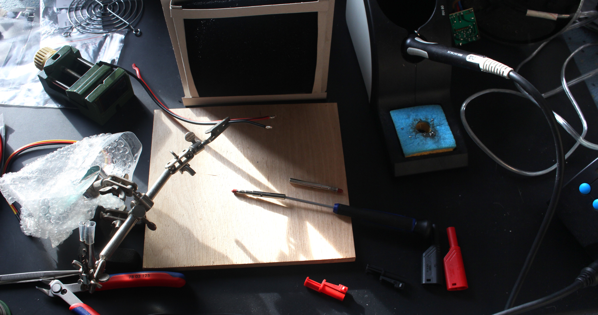
This here is to improve the cooling-bodge I have on my DIY-audio rack. Currently it is a 3rd Hand holding an old PC fan I had on hand, random wires stuck into the Tamyia-Output of a simple racing pack charger (as in: it is a constant current supply, 11.2V DC Powerbrick).
The goal of the adapter cable:
Not short out the powerbrick
Allow for monitoring of voltage or feeding from my bench PSU
Be useable to check fan headers on mainboards
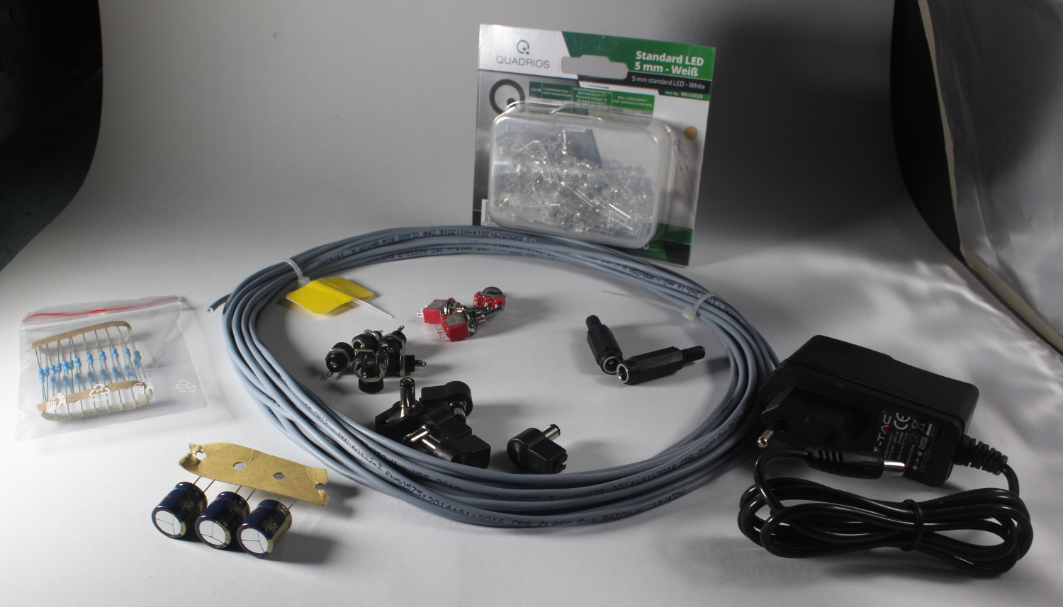
With that said, I present the parts:
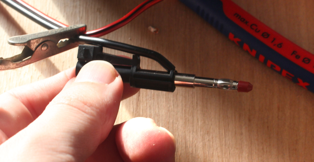
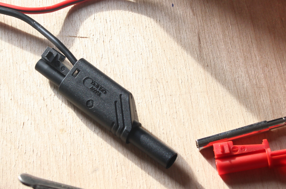
To hook up the lab-connectors, I just used som speaker cable I had on hand.
There is a small grubscrew in the contact pin, just wind that back and stick the wire in.
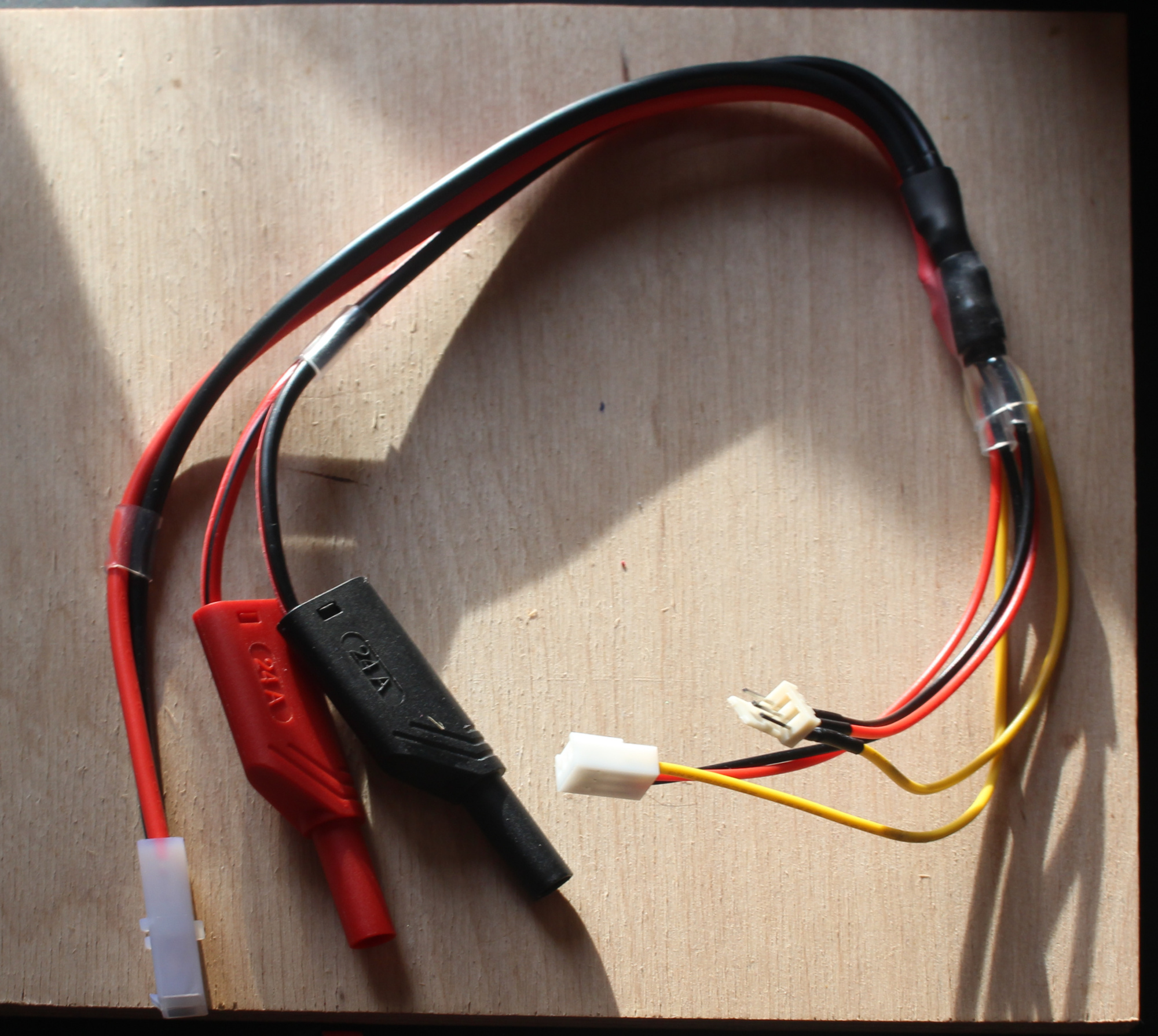
I cut the power part of the fan extension, soldered that to the lab and Tamyia connectors and done!
Came out better than expected but worse than it could be.
I now also have the L-profiles to put the LEDs into.
Plan looks like this:
Have two barrel sockets so I can feed power through, then a switch followed by a capacitor for smoothing.
And then there is the 7 groups of 3 LEDs. Fed from a 12V PSU (because they are common and cheap).
Anyone here using Ledcalc.com whenever you need to figure out the resistor value before the LED? Here is how to do it manually: Us = 12V ← Voltage from the PSU Uf = 3V ← Voltage drop per LED Ur = ? ← Voltage to apply Ohm’s law to If = 16mA ← will still be spotlights x = 3 ← Number of LEDs in series R = ? ← The Resistance you are looking for
The magical formulas: Ur = Us - (x* Uf) R = {Ur \over If}
Replace Ur with the formula and get: R = {Us - (x* Uf) \over If}
Stick some values into it: R = {(12V - (3* 3V)) \over 0.016A} R = {(12V - 9V) \over 0.016A} R = {3V \over 0.016A} R = 187.5 {V \over A}
And instead of writing V \over A (not to be confused with VA), we write \Omega R = 187.5 \Omega
187.5 Ohm is not an easily available resistance, so just use the next step up (220 Ohm) for 13.6mA current through your LEDs.
Lastly, you need to know how much power the resistor is going to see. 1/8 Watt is probably fine, to be sure: ?W = Ur * If
In my case, this is 41mW, or a 3rd of the load a 1/8W resistor can take.
Lastly, the drawing of what I intend to build:
The LEDs in the group should be so close I can just solder one leg to the next, not sure what I am going to do to link the groups.
i agree on plexi. Is a common trick also used to “bend” light, and even without sanding could give enough diffusion to look good.
if you end up with issue managing the heat, mount the LED strip on a aluminum strip to act as heat sink, but i think your mounting has already enough spread
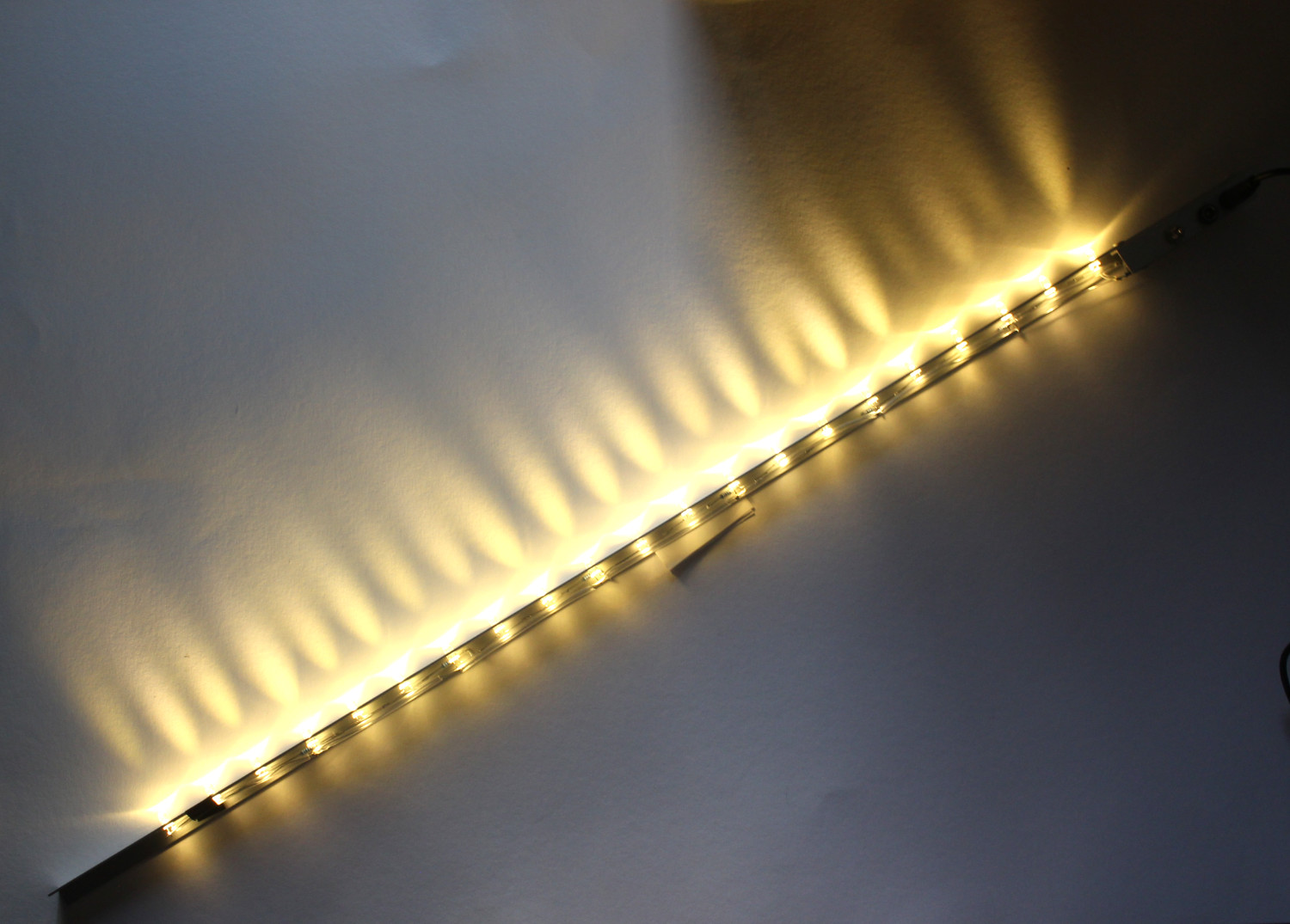
All 3 bars done!
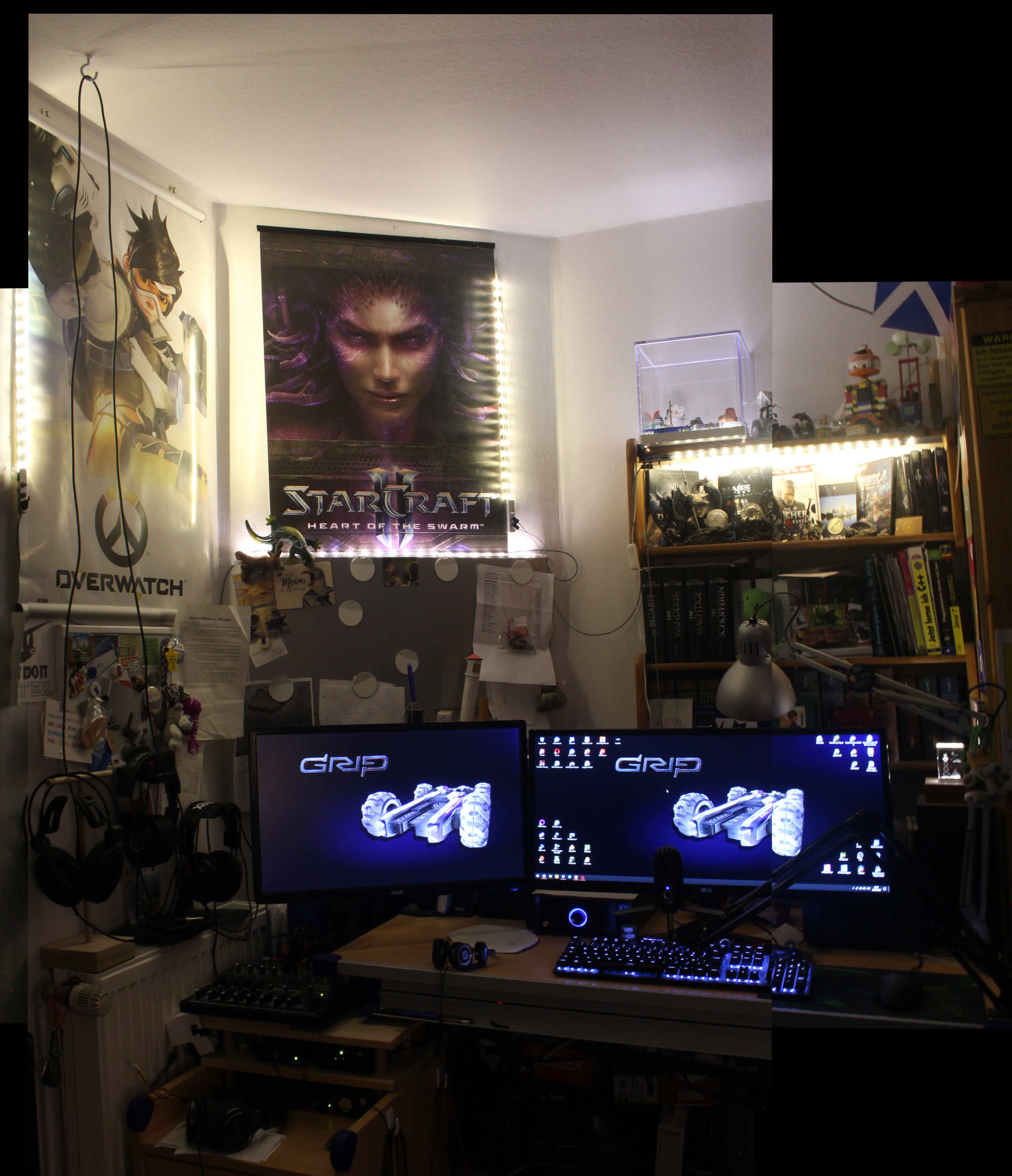
I deviated from the plan to hang a pair next to the SC2 poster and instead put one on the left next to the Overwatch poster (which I would like to replace, different topic)
Had to stitch two images together to make this fit. Is about as bright but a bit colder than it is in reality.
The one with the plastic cube?
Items from my life so far. Toys, a piece of my sand box, an anemometer I made in school, souveniers from various places, wristbands from LAN-parties, a music box, etc.
Honestly, deserves a lot more love and care than all the items recieve.
Below that, are some more items and an assortment of my favourite games.