A fellow student has a Rigol scope and also mentioned that.
Thing is though: Only one knob for all 4 verticals.
Looks like a battle of the 1054’s
A fellow student has a Rigol scope and also mentioned that.
Thing is though: Only one knob for all 4 verticals.
Looks like a battle of the 1054’s
I have 2 that I use one is a 15 mhz techtronics dual sweep for heavy work ((yeah I know an old clunker) and a pocket oscope the size of a cell phone. touch screen but far more portable.
you can get usb scope modules that you can plug into any computer.
Keysight scopes are damn good quality.
the biggest consideration you need is what you want to be able to do with the scope and compare its features. If all you are doing is basics of scope use then buying a super scope is a bit of overkill.
here is where preparing to delve deeply into electronic engineering that buying a high quality scope will make more sense.
as you progress you will use many if not all the higher functions of your scope and learn a few workarounds with them.
the same can be said with a good vna meter(vector network analyzer)
I purchased the nano vna and there are a lot of functions this thing can do. so far I have tuned antennas, analyzed swr, and measured qrp power output.
there is a lot more i have to learn on it but it was worth buying. ( a heck of a lot easier to measure a toroid than with an oscope)!
I know. We have some pretty nice (and dang expensive) ones from Keysight at Uni.
Feature wise, a useable FFT would be useful. I am not sure how long 2 channels would last me.
I don’t need any logic analyzer functions as I am usually not that deep into ICs.
Edit: Actually, 4 channels would be enough to troubleshoot that one semi-dead BluRay/HDD player I have here. So 4 ch is a must have now 
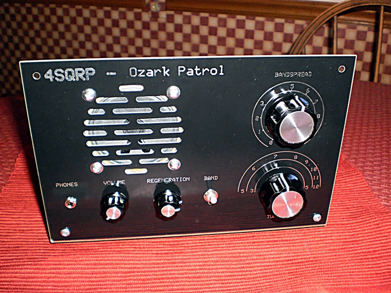
Im working as a kitter /builder for the 4state qrp ozark patrol shortwave radio
these cool radios are easy to build and a lot of fun listening to broadcasts from around the world!
Idea:
I have an Emotiva BasX A-100. Drives my (shitty) speakers on my desk and some headphones. The internal jumpers being “modded” to half the output resistance.
Still leaves the noise floor too high to be used with sensetive headphones. Not that my LakePeople G103-S does not satisfy, just sometimes I need more dirt, so to speak.
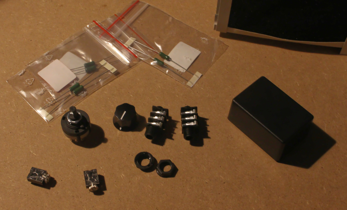
So, why not have a variable resistor box?
Contents:
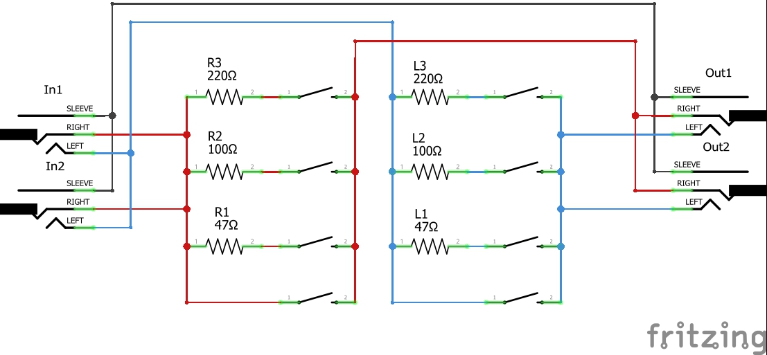
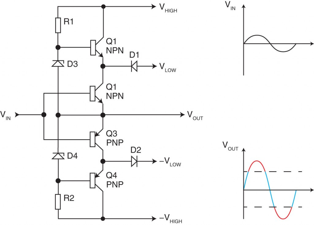
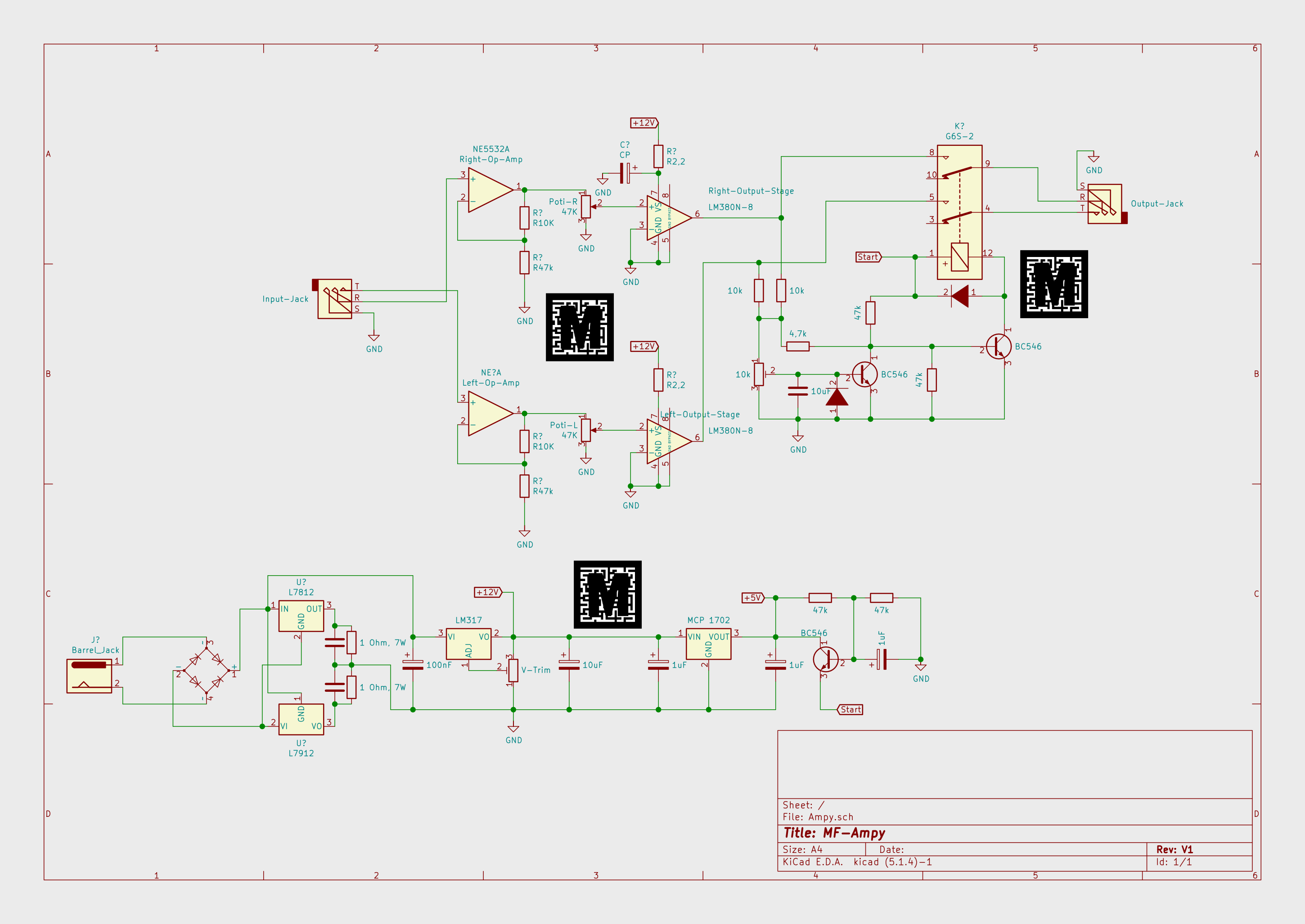
Schematic
For those playing along at home:
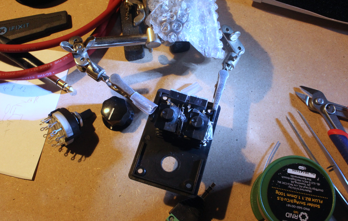
The Build
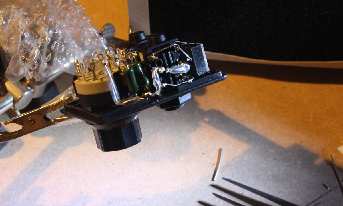
As hinted at above, the box is technically too small. But with some cheating, I made it all fit in:
3.5mm and 6.3mm jacks installed to the lid:
Resistor for right side in place:
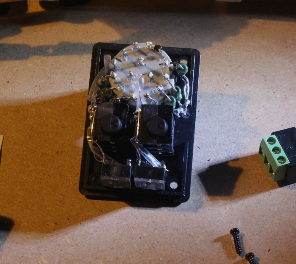
Both resistor banks in place. The left side “return”-wire actually loops around under the rotary switch to the other side. Just buy a bigger case if you do this yourself.
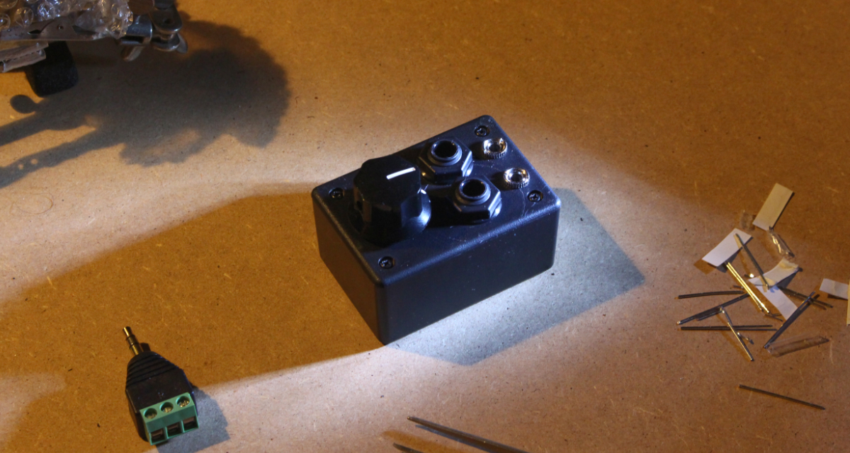
Done!
Note: This is basically a duplicate of a post I made to a different forum. Because that forum is even less electronics focused than this here (it is a hi-fi forum after all), I hope to get some thoughts from “engineer in the heart”-people here.
In the unlikely case someone from that forum made their way here: Say hi!
Project Name for now is MFHP (“mixture” of RNHP and the initials of my user name).
Preamble
Comming from a digital tinkering background, analog fascinates me. The fact I recently fell into the audio (specifically studio and headphone) rabbit hole only fueld that.
Amplifiers exist in call kinds of configurations. From a single switching element to a multitude of passive and active components, DC or AC coupled, etc.
I like the benefits Class AB provides. It combines the efficency of Class B with the distortion of Class A.
As such, AB competes with Class D for most common amplifier (if we ignore Op-Amps, but those are cheating  )
)
The Idea
Class A despite its simplicity is hard to get right.
Class B sucks (distortion)
Class C does not work well for audio
Class D is… eh?
Class…
To cut this short, I want to build a Class H (It was pointed out to me on an electronics forum that my design is actually Class G… ) amplifier.
No idea if this is a good idea or remotly fit for driving headphones, but that is where the fun is, right?
Concept
Don’t trust the incomming power - A lot of (expensive) audio gear has power supplies that have nothing to offer against a good quality computer PSUs in output ripple and EMI rejection. Linear bench PSUs nearly always outperform “audiophile power supplies”, for a fraction the cost.
I hope to have enough input filtering to get this right.
No direct Grid feed - This is mostly because it makes it easier to get this to market in a certified state, should I chose to enter the hell that is hifi. Different story.
No Integrated Components - (spoiler: This was kicked out very quickly). I want to have something not based on highly specialised magic-in-a-chip devices.
This was kicked out becaue a pair of high quality integrated line buffers (not Op-Amps!) are way more convenient than trying to come up with a decent input (= pre-amp) stage.
Switchable AB/G Operation - Becaue Class AB and G are so similar, this should be easy as having some relays re-route the signal (spoiler: It is never easy)
By now, I am more than a month of thinking and simulating into this project. I have a better idea of the scale of things and improved my analog circuit knowledge a lot!
Stay tuned!
…is a bit stuck. I need tools I don’t have (Ocilloscope, multi-rail PSU, electronic load) to learn about a subject I have a glimpse of an idea off.
I could just buy the components I think I need to build this and then guess my way towards victory.
I looked at this a bit, read some forum posts, blogs and watched a hand full of videos.
It is all analog, the components are super basic and everything that could go up in flames costs less than 1€ to replace.
The bare circuit including the required heatsink for the MOSFET is 10-ish €. As I don’t like another bare PCB to float about near my electronis tinkerings, I need a Case (24-ish €) and don’t want to tie my only multimeter up, I need a panel mount current meter too (10€).
This puts the total project cost at 1/3rd of the cheapest electronic load I could find.
Context:
I have some experience with Keysight 2000-series (or 3000 series? Not sure) and various older CRT based HP scopes from the labs at university.
The HP scopes had those nice analog coars and fine stacked knobs.
The 2000-series Keysight scopes are absolute units and were brand-new when I began studying there in 2016.
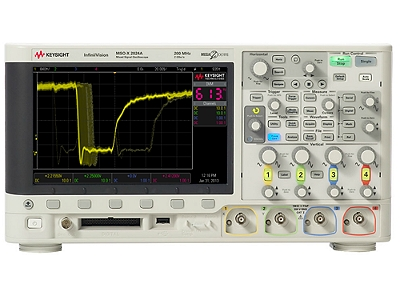
While I also have some gripes with them, they are nice out of 10. Then again, not home-gamer prices
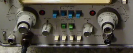
First Impressions on a Rigol DS1054
I have a friends Rigol DS1054 on loan. While that is super nice and will help me a lot to get my uni-project towards completed, I HATE how the vertical adjust is done!
Order of operation is channel button, then adjust knob. And it is not even one detent, it is always two! WH?!

Not sure if this can be configured, but the level adjust does “righty loosy, lefty tighty”.
Horrizontal adjust is good too.
Minor gripe here is that persistance time locks out and “drawing style” is locked to dot instead of vector when you select X-Y. Whatever 
The Trigger menu is nicely done. Came in handy while getting myself back up to speed on the quirks of the 5V and 15V regulators in my uni project.
Falling-edge triggering was a 5 second job.
Math-menu works nicely. FFT is a bit slow, then again, home gamer budget.
Preliminary Verdict
Yeah, no…
This will definetly get the job done, but I would not buy one for myself (or the Siglent 1104 for that matter). The vertical adjust just pisses me off too much!
PS: Should you, be the person who lent me his oscilloscope. Thanks buddy for trusting me with your precious 
I learned two things about amplifiers:
I decided to take a step back. Glass G is still the goal. The complexity of the endevour is like learning C++ by creating a Vulkan accelerated game engine: Probably possible, definetly banging your head against the wall.
To make my life simpler, I kicked out everything I don’t need to make an amplifier.
So I take some known working assemblies and some experimental ones. From my uni project, I know Op-Amps for how simple they seem, are can be a big PITA.
The Class G monster still keeps “MFHP” as project title. It is the big boy.
This side-project, research project if you will, is the “Ampy”.
Instead of doing this like my other electronics projects, I will take this on like my programming projects:
End Goal is set and can only be moved if it hinders the project itself.
(Don’t shoot for the Moon and Miss!)
There are no Problems, just Challenges.
Back to Front.
(The outcome is the Goal, the Path makes itself)
In Practice:
I skipped the block diagramm.
This removed a lot of the removing duplicates I ran into on the MFHP. Instead I just got the spec sheets of parts I hope will play nice in the arrangement I will put them in.
I went into my small collection of PCB shots from various amplifiers in all price ranges. From el-cheapo Chi-Fi to top of the line engineered and made in the USA, Germany and elsewhere.
No need to do what others did better, no use in replicating others mistakes
I took a page from Fried Reim’s “The Headphone-Amp Cookbook” ← German
While following all of it would just result a home brew Niimbus US4+, some of the concepts described will definetly find their way into the Ampy and later the MFHP.
First circuit drawing was just a sketch.
Just a quick and dirty “does this look right?”. Ironed out some minor thingies, stumbeled upon the difficulties that is the datasheet for the LM380 and dumped a solid 3 hours into Ki-CAD instead of my beloved Fritzing.
And this should be it:
I am yet to double check it, run simulations or anything.
If anyone here spots some wierdness or points where I am to shoot myself in the foot, please tell me!
Edit: There is no power switch 
Note on Ki-CAD and Fritzing:
Fritzing is great. Simple drag&drop to get 95% of all Arduino or other uController board based projects done. The inbuilt Arduino IDE is a nice touch.
Going to Ki-CAD coming from Fritzing is a small step. While there are some differences, most of them have to do with hotkeys I have not yet looked up or memorized. The component placement and the component manipulation take some getting used to.
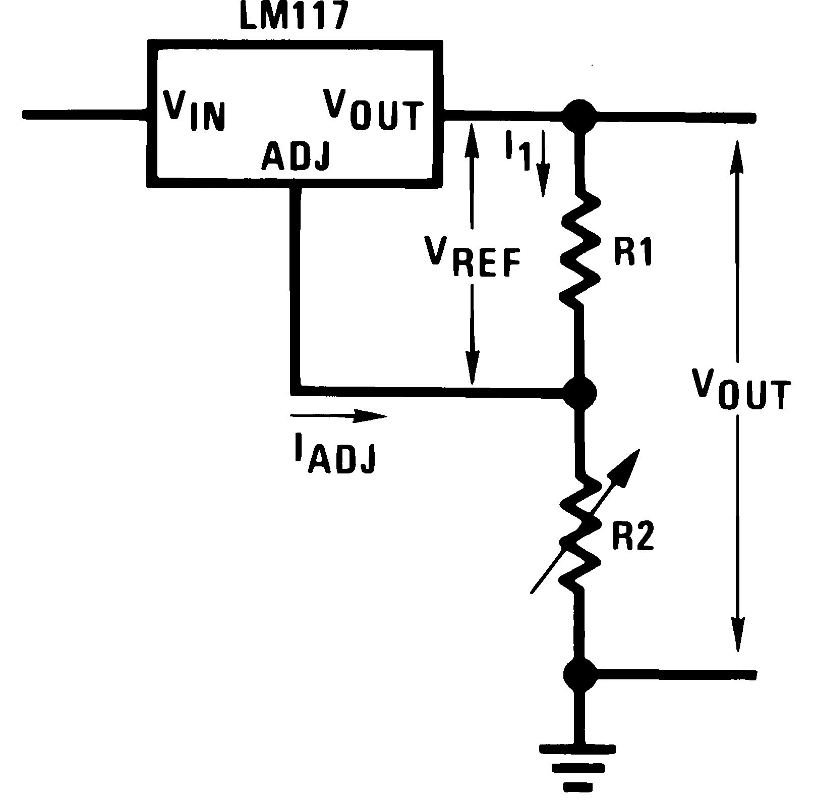
Two things; Is that the correct way to control an LM317’s output voltage with a pot? When I checked the datasheet, it doesn’t appear to be, and online, this schematic is given
Also, if you know you’ll be creating 12v from the LM317, why not instead use a basic resistor divider?
Edit: changed “basic voltage divider” to “basic resistor divider”
As R1 and R2 form a voltage divider, and a potentiometer when wired like I have it also is a voltage divider, it should work.
The Formula Texas Instruments has for calculating Vout is this here:
Vout = Vref(1+ \frac{R2}{R1})
If this comes back to bite me, I will go back to the fixed resistor for R1.
Because the current draw is not constant.
DIY Lighting - Minor Update
I want to integrate 3 small, previously battery powered, thingys to the system.
And this layout here looks good:
Except the pinout of the LM317 is exactly reversed from the layout it is in now. Have to do some more thinking before soldering anything…
Meaning that you also want the LM317 to output a CC?
I need Constant Voltage, which is what the Linear Regulator will provide.
Current will vary a lot depending on what the amplifiers are doing.
I thought that if you use the voltage divider for the LM317 (240ohm for R1, 2064ohm for R2 (if that value actually commonly existed) to get 12v), it’ll allow for varying currents, but continue to maintain the 12v output? Would that not work for you instead, and be cheaper + simpler?
From what I’ve read into the LM317, generally you want R1 to be 240ohms (anywhere between 100-1000ohms is fine) as well.
IDK, I’m just a nooby (as you know), so enlighten me lol
2.05k ohm exists, would give 11.927V. I probably still have some of those as 12V is quite the common voltage for electronics.
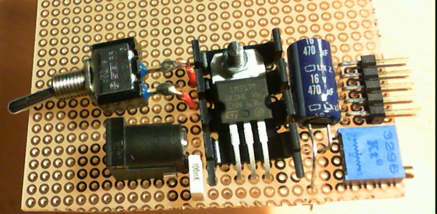
That said, I usually have a 120 Ohm for R1 and then dial in R2 while monitoring output with a multimeter.
The test I am doing here is if I can kick out R1 and replace it with the input to wiper of the trimmer.
Ah ok interesting!
Well I can’t wait for you to keep posting updates on this! Funny enough, you’re planning on using the NE5532, which is the same IC you recommended to me for my own (albiet much simpler) amplifier
I found out, you can’t do that.
Edit: NVM had my bench PSU set too low. This may work 
After some more puzzle work, I got this figured out and soldered. Works as expected and will now be in service until the electrolytic cap dies.
Pics?