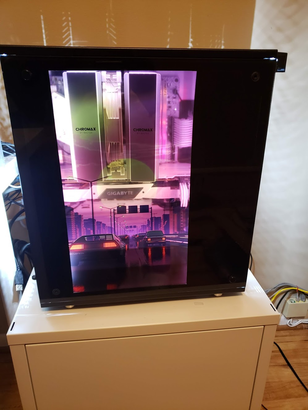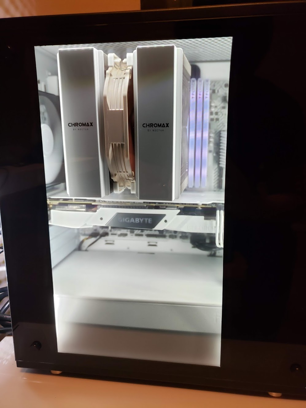
Time to celebrate! The build is finished!
If you have any questions or comments, feel free to ask!
That thing is sweet!
I’m surprised which how many white PC parts you found. I had no idea you could make a pure white build.
White PC parts are extremely limited for sure! In fact, the motherboard was discontinued just a few weeks after I bought it which is quite unfortunate.
I was tired of all the generic RGB builds, so this build is one which strives to go against the trend.
Looks absolutely amazing! Monsterous!
Very original bro. Great work!
Be sure to DM a mod to get the builder “build log” badge.
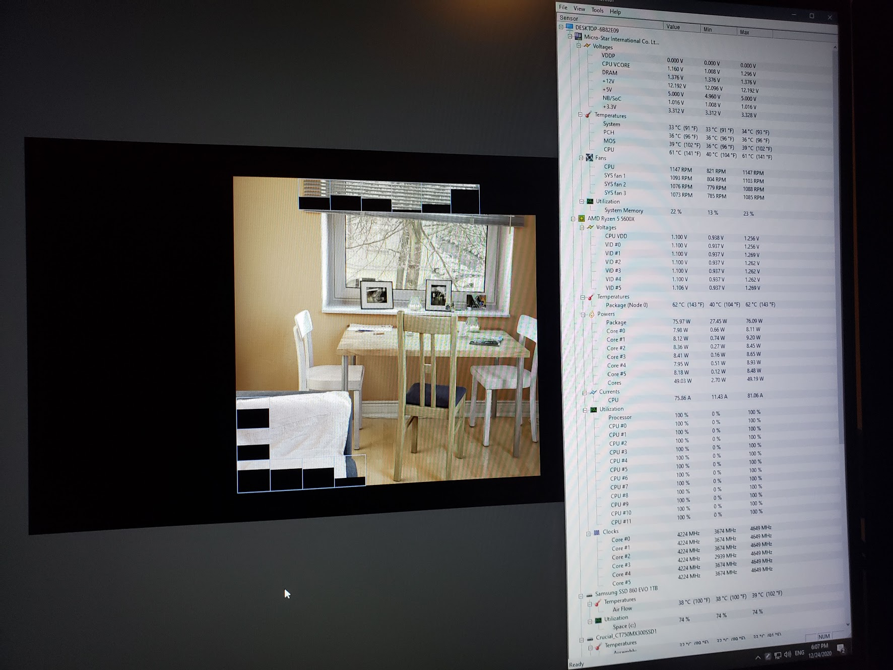
Is there a way to feed system data like CPU/GPU temps and load onto your case?
But what you’ve done is so cool.
If you hook up the monitor as a secondary display, it should be very easy. I have mine running off a seperate intel compute stick so I don’t mix refresh rates in Windows though, so it would be a bit tougher.
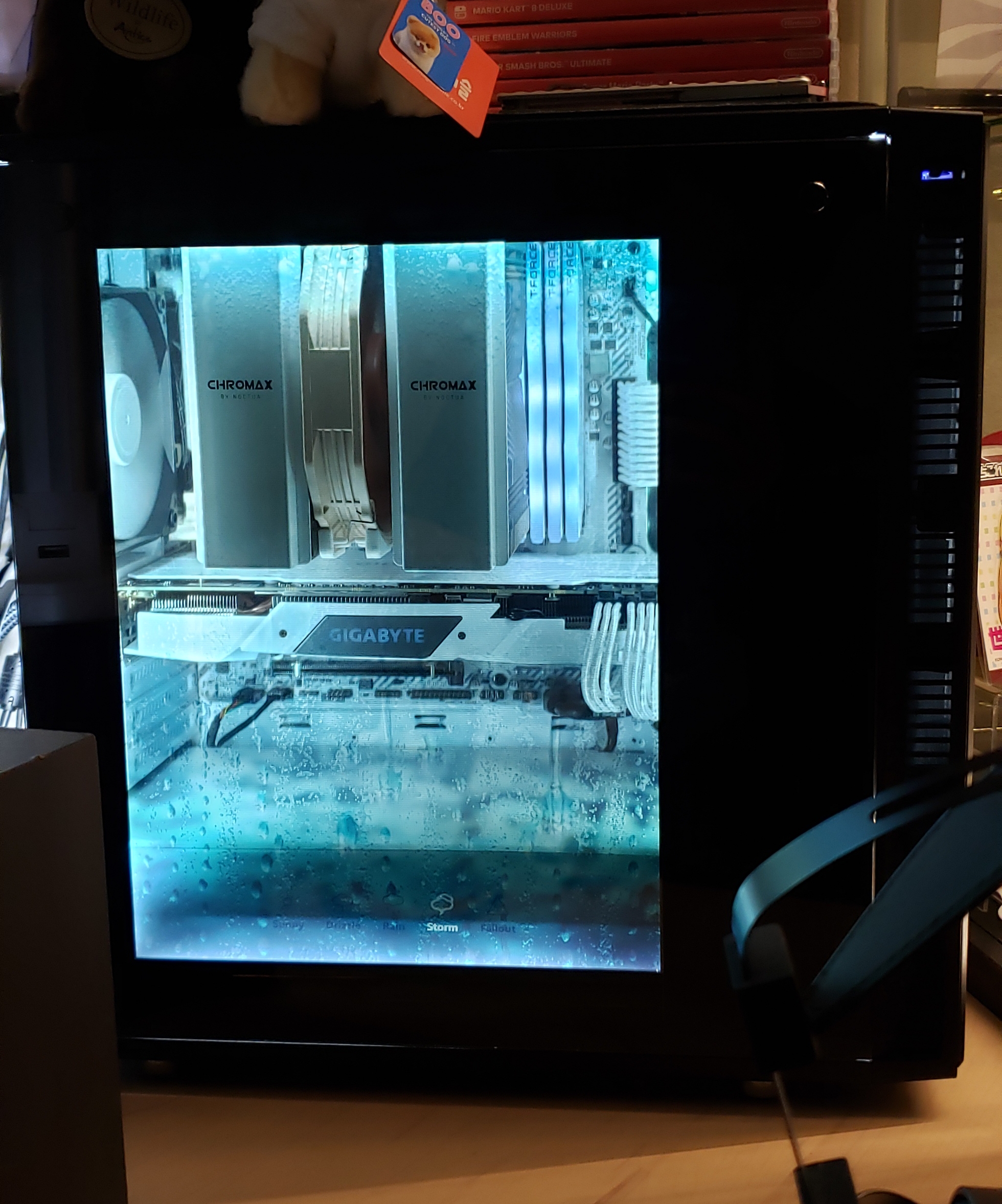
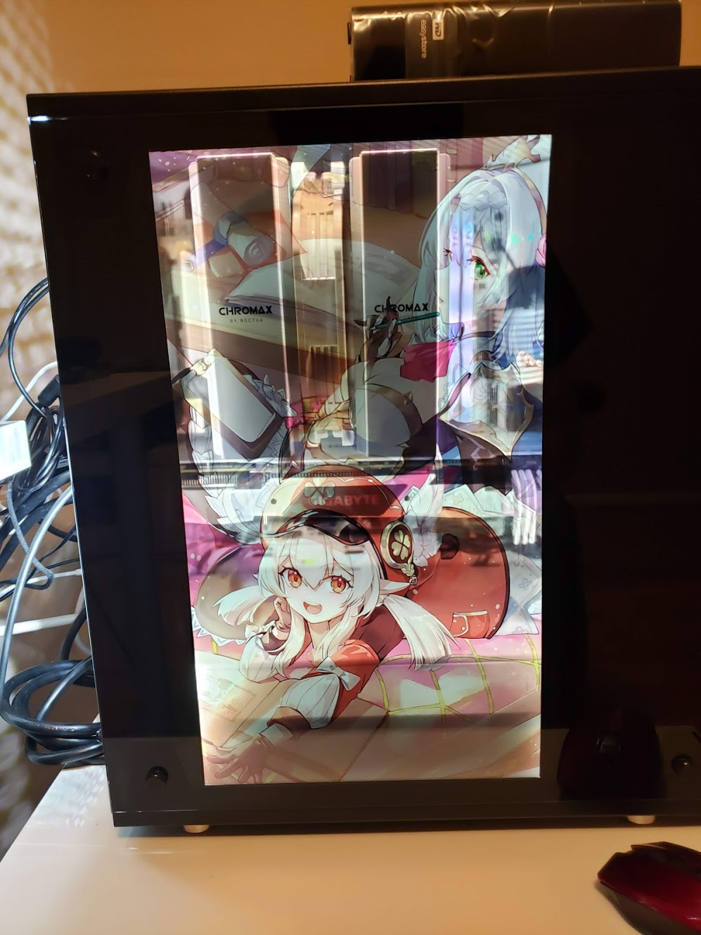
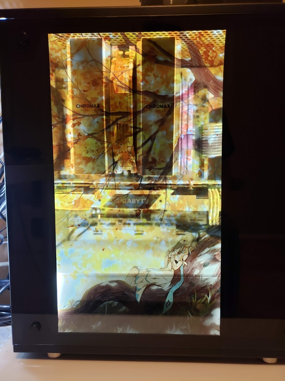
On another note, found a new wallpaper which fits my build pretty nicely.
As you can see, I now have 4x8GB of ram since my kit went on sale again. Overkill, but looks awesome.
Very well done man! Looks great, and your video makes perfect sense to me.
Guys, if you want to help support @Some_Tech_Noob please give his video a like (I know it can be easy to forget with embedded videos).
From what I can tell he’s put a lot of research and time into this very cool and well made project and he even took the time to make a video explaining how we could do it, I think that deserves a good bump on YouTube.
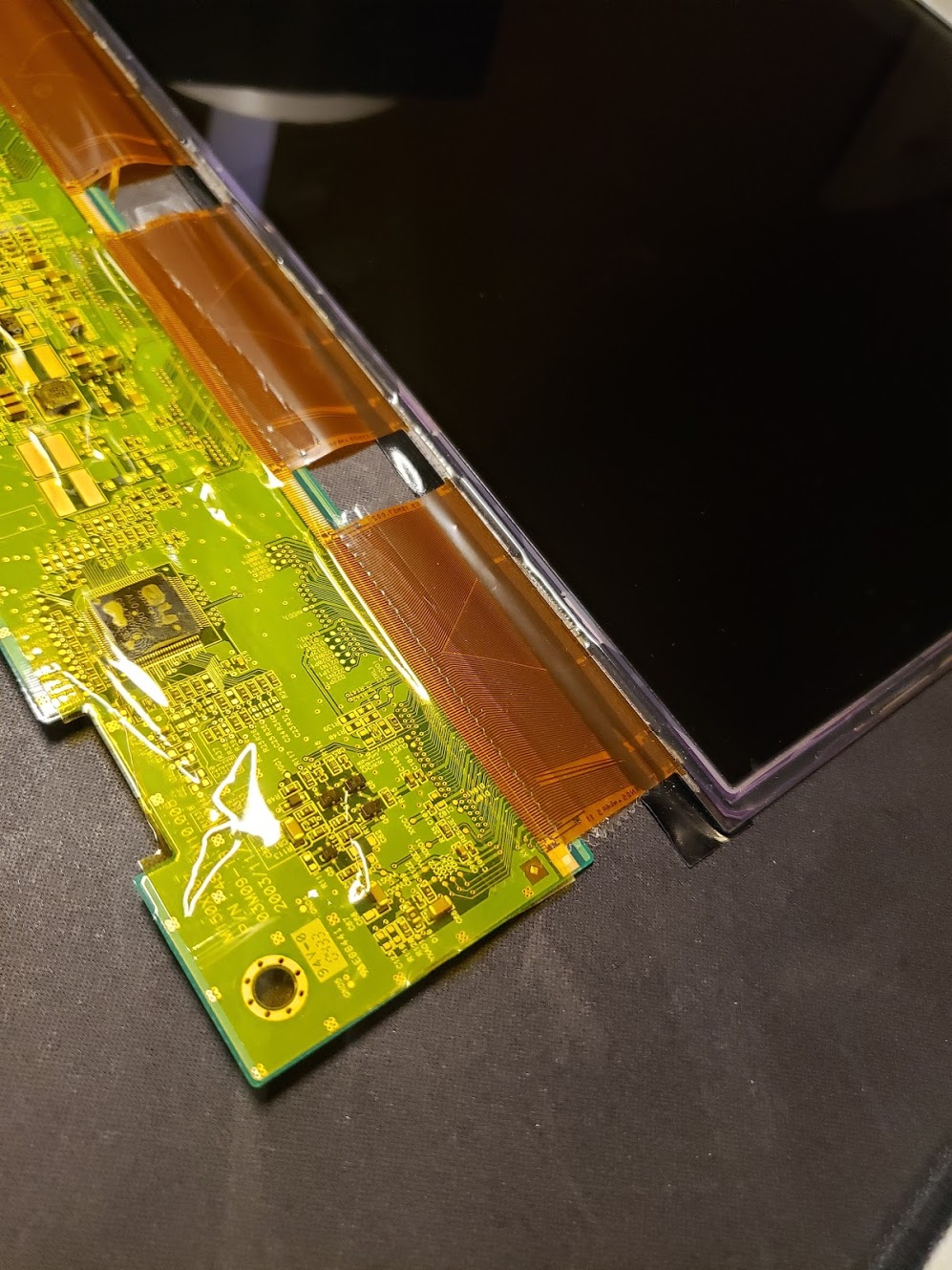
2020-12-13 Update: Oopsies.
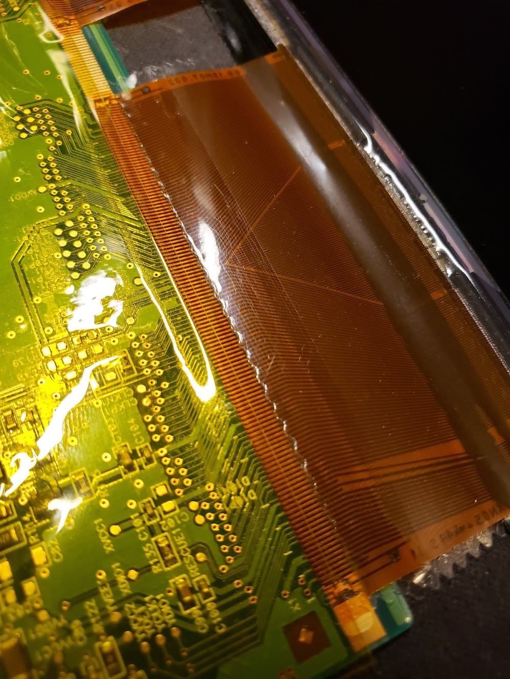
Well uh, I accidentally ripped off one of the ribbon cables on the LCD when taking apart my PC for some debugging/overclocking/cleaning. There were definitely some flaws in v2 of the mod when it came to durability and serviceability - which I hoped to avoid by being careful. It just took one time of me being sloppy to wreck it all. I tried to align the pins and tape it back together, but the LCD displays garbage lines now.
After doing some research, It looks like the ribbon cable is heat sealed to the PCB at the factory - and it theoretically is possible to re-seal it back on with a soldering iron or something, but the success rate is low due to the ridiculous amount of connections that have to line up.
This was back in August. I’ve unplugged everything related to the side panel LCD since then, but was too lazy to remove the mods since my computer still works fine with or without them. I don’t have any more monitors to take apart either. After pondering for a week whether or not to go back to a basic case or re-do the mod, I chose the latter. LCD Side Panel v3!!
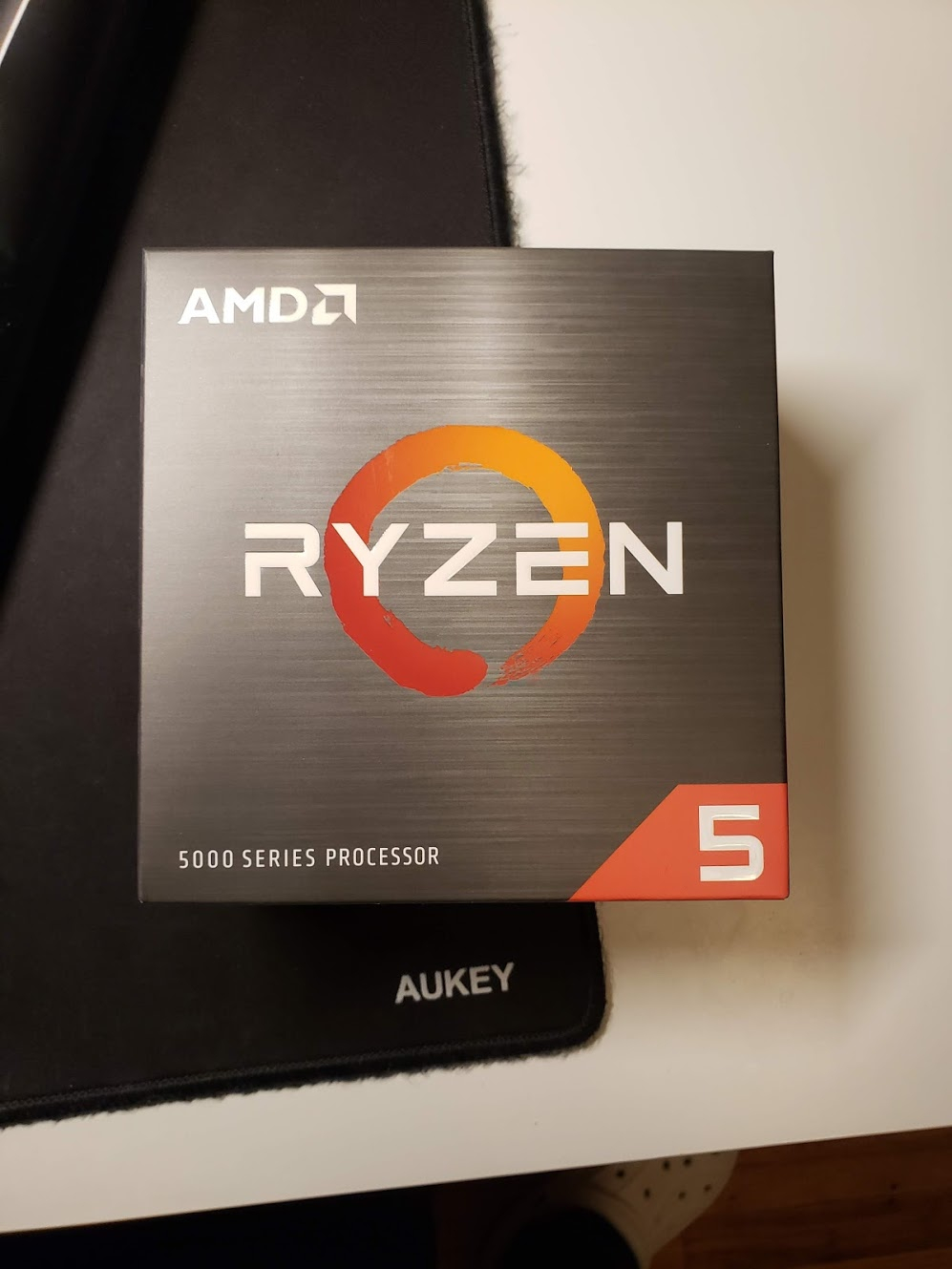
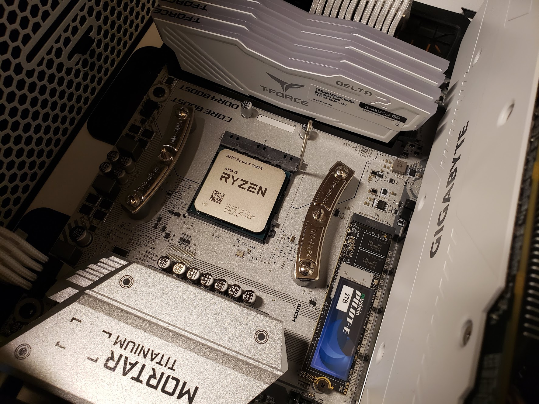
So there you go. Assuming all goes well, a revamped version 3 is coming soon. Also got my hands on a Ryzen 5 5600X yesterday at Microcenter since my $150 1700X was intended to just be a placeholder until Ryzen 3000. Now I just need to wait until MSI pushes out an update to the B450M Mortar Titanium sometime this month to actually use it. Meanwhile, my 1700X will slot into the ASRock B450M Pro4 I purchased as a combo and become a second pc. Why not use the B450M Pro4 which already has beta support for Ryzen 5000? It’s not white.
So since I now have a soft deadline of whenever MSI pushes out the bios update for my motherboard, I spent a bit of time today working on the new mod. I ordered stuff from AliExpress back in Aug/Sept, so everything’s been sitting in my closet just waiting to be modded.
What’s different between v2 and v3?
The idea is the same. Disassemble a LCD, figure out how to power it with the ATX PSU, and mount everything. However, instead of buying old 4:3 monitors on Craigslist for $5-$10, I’m trying the next most popular route. Purchasing laptop LCD panels and a compatible controller. This is much easier because you don’t have to figure out the LCD Controller board’s power pins and voltage. I can also source an IPS panel for much better viewing angles. The viewing angles on my old side panel LCD were extremely bad.
The Goods:
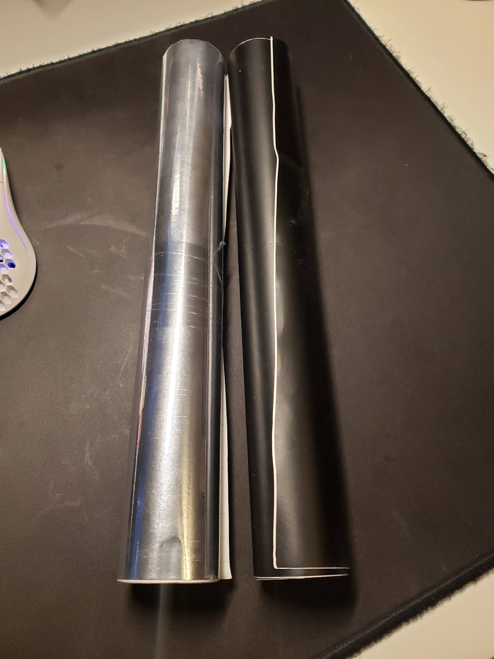
Matte Black & Chrome Vinyl - $9.29. I want to try doing chrome on the inside of the side panel to reflect more light.
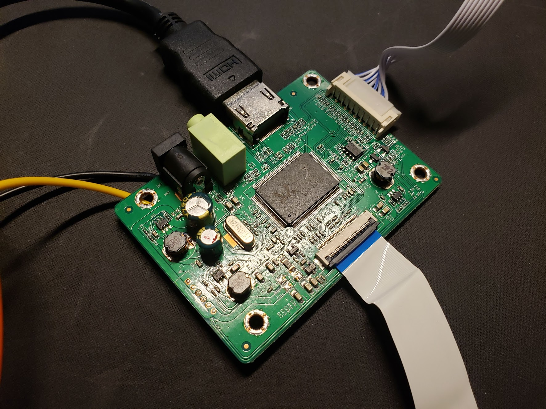
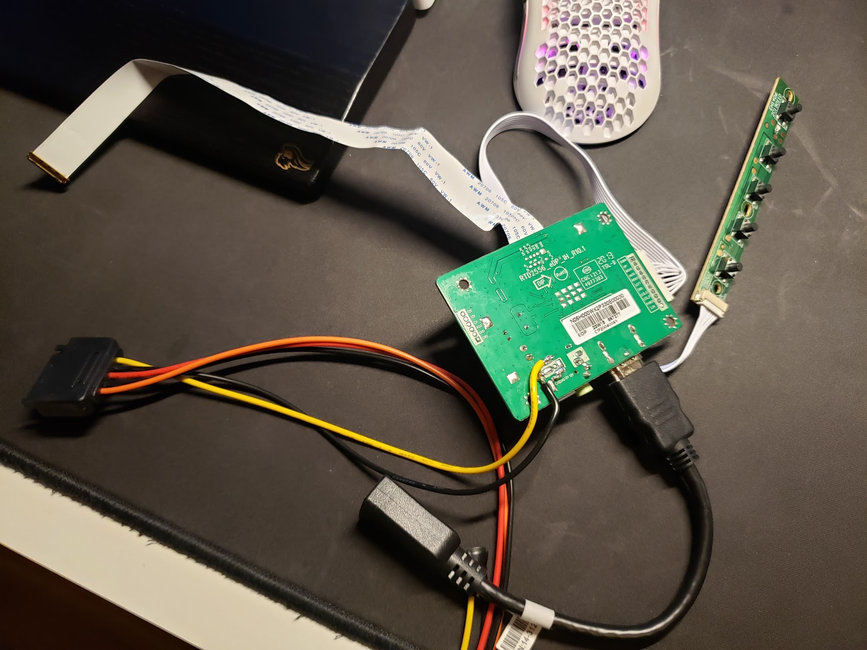
eDP LCD Controller Board - $13.09. Aliexpress listing usually lists the compatible LCD panels.
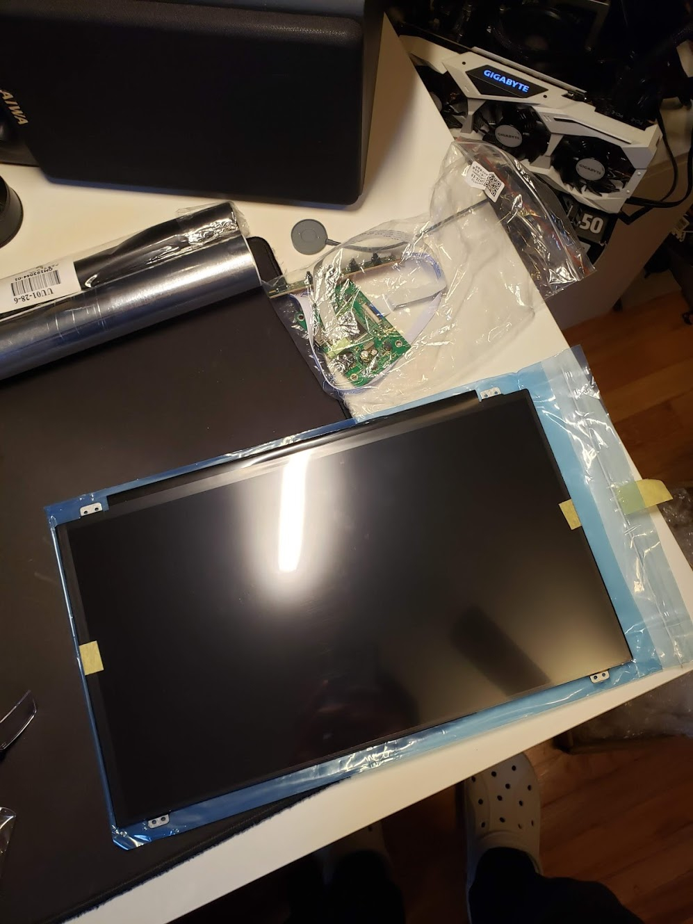
LCD Panel N156HGE-EB1 - $44.52
Purchase another SATA extension cable. Use your imagination.
My Ryzen 5 5600X 
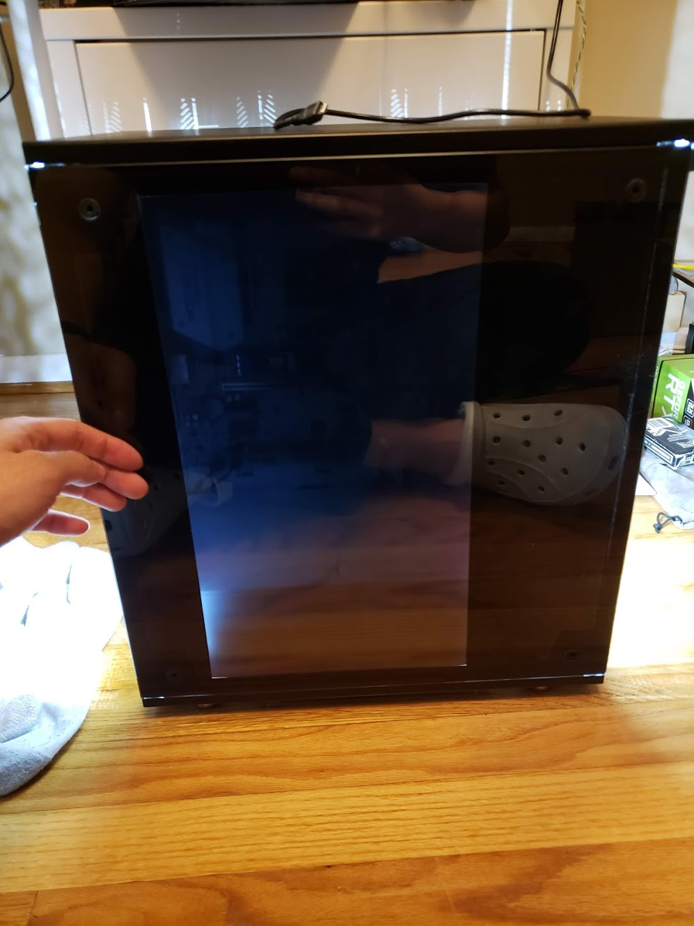
Time to get to work
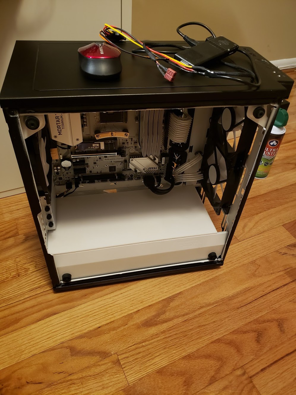
Took apart my PC. Also removed the lcd from my side panel and removed all the old vinyl too - side panel is back to it’s clean, original state.
Figured out the the 12v and GND power pins to solder my SATA extension to.
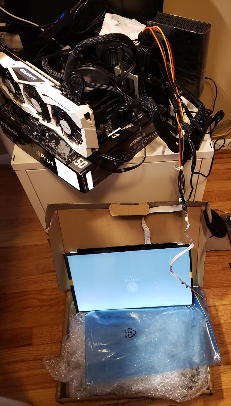
Testing the LCD powered off the PSU & Compute Stick
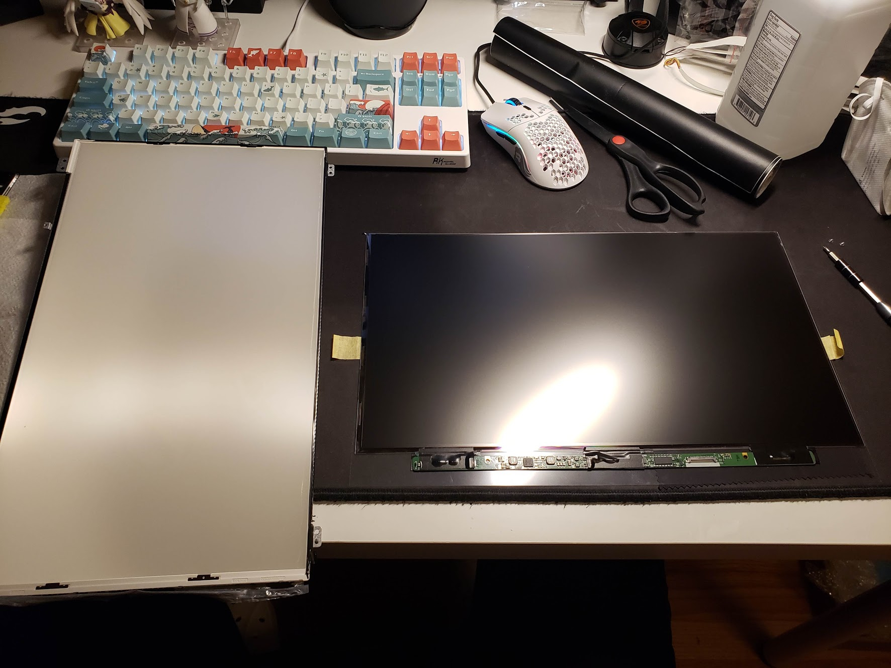
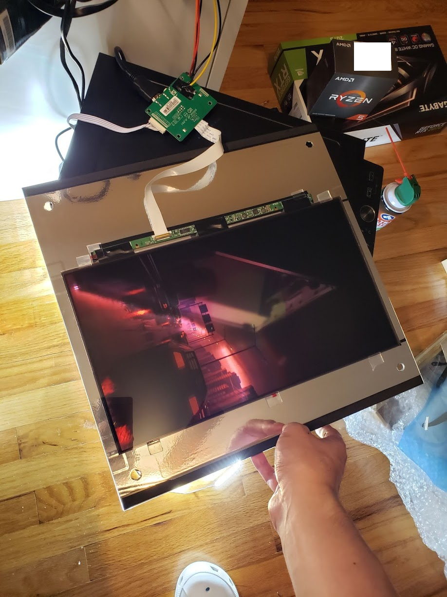
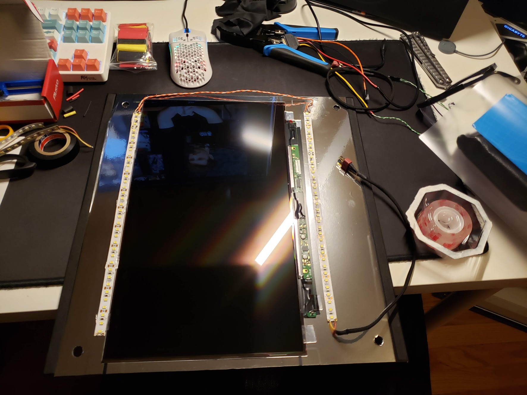
Disassembled the LCD. There was some sort of black tape going around the whole thing to keep it together, as well as some light adhesive around the backlight. Spent way too long trying to peel it off. Ended up just cutting the last 2 sides and i think it looks cleaner too. Since this is a laptop LCD, it’s a LOT thinner than the dell desktop monitors I used previously. I also reinforced the ribbon cables with electrical tape on both sides since these looked infinitely more fragile than my old LCD.
I didn’t even test the LCD after it was disassembled in fear that I’d damage something - the panel feels ridiculously fragile.
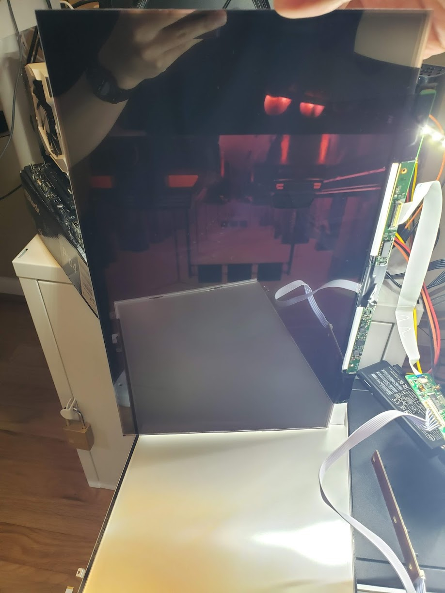
Oddly enough, there seems to be some sort of diffuse layer/anti glare coating on the reverse side of the LCD, despite this LCD being glossy. I really hope this isn’t the polarizing layer. According to this video:

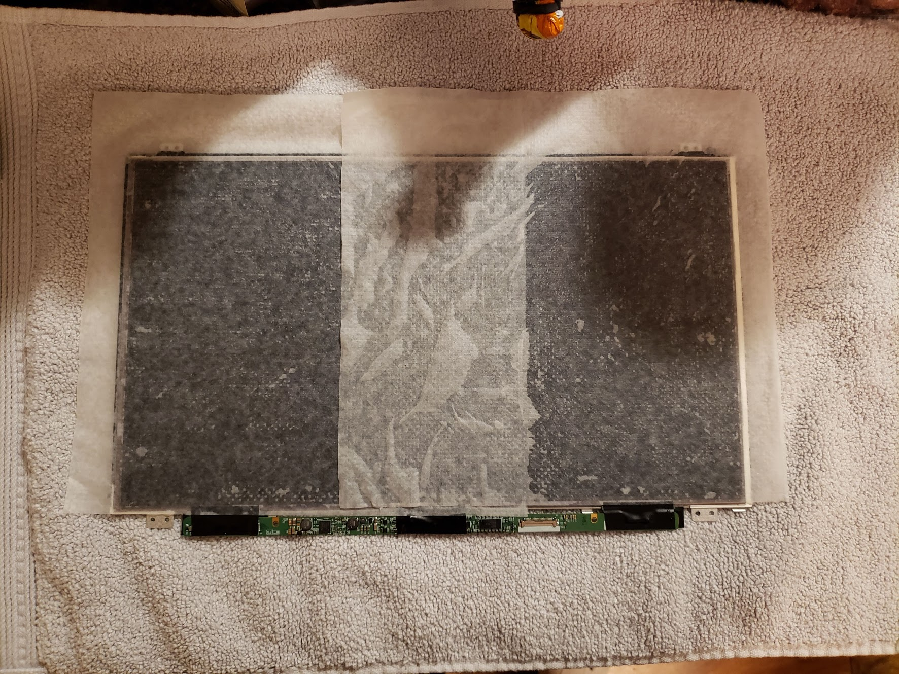
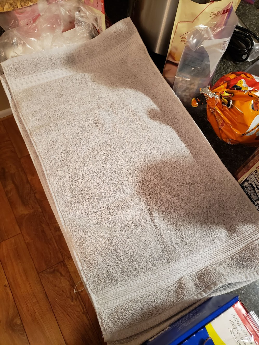
One layer of wet paper towels shown here. I layered on 3 more, totaling 4 wet paper towels.
Covered with another towel to hopefully stop the paper towels from drying out too quickly. I will likely wait overnight at minimum before trying to peel off the anti glare coating, because I am not taking any risks on such an expensive part.
That’s it for today. Hopefully I’ll have good news for y’all soon. Thanks for reading!
edit: 5 hours later, I gave the peel a try. Seems to have come off smoothly! Now I gotta wait for everything to dry up and give it a test.
2020-12-15: Side Panel progress!
So I had a pack of the typical 3-fold commercial paper towels that I have been using in order to try to loosen the anti-glare film. Turns out these things absolutely suck at holding water. I used some actual paper towels and the anti glare film peeled right off after laying down a few coats of wet paper towels.

I let the LCD dry overnight and gave it a test. Looking good!

One thing I do notice differently about this panel is how much light it blocks out when powered off. My previous LCD blocked a lot of light, but this is on a totally different level. I expected this coming in since it’s always harder to punch light through smaller pixel sizes, but didn’t really factor that into my planning.

Double layer vinyl filmed the side panel and mounted the LCD. Matte black vinyl for the first layer, then the chrome. Some dust specks got under the vinyl which is unfortunate, but I don’t have the tools here to prevent that. It doesn’t bug me too much though so I didn’t bother cutting new pieces of vinyl. Electrical tape to reinforce the ribbon cables and reduce the risk of short circuiting on the vinyl(if it’s conductive, it shouldn’t be though…). Secured it firmly to the side panel with some mounting tape. So now unless I really rip something, the only thing that will probably fail is the connector at this point.

Looking pretty good!
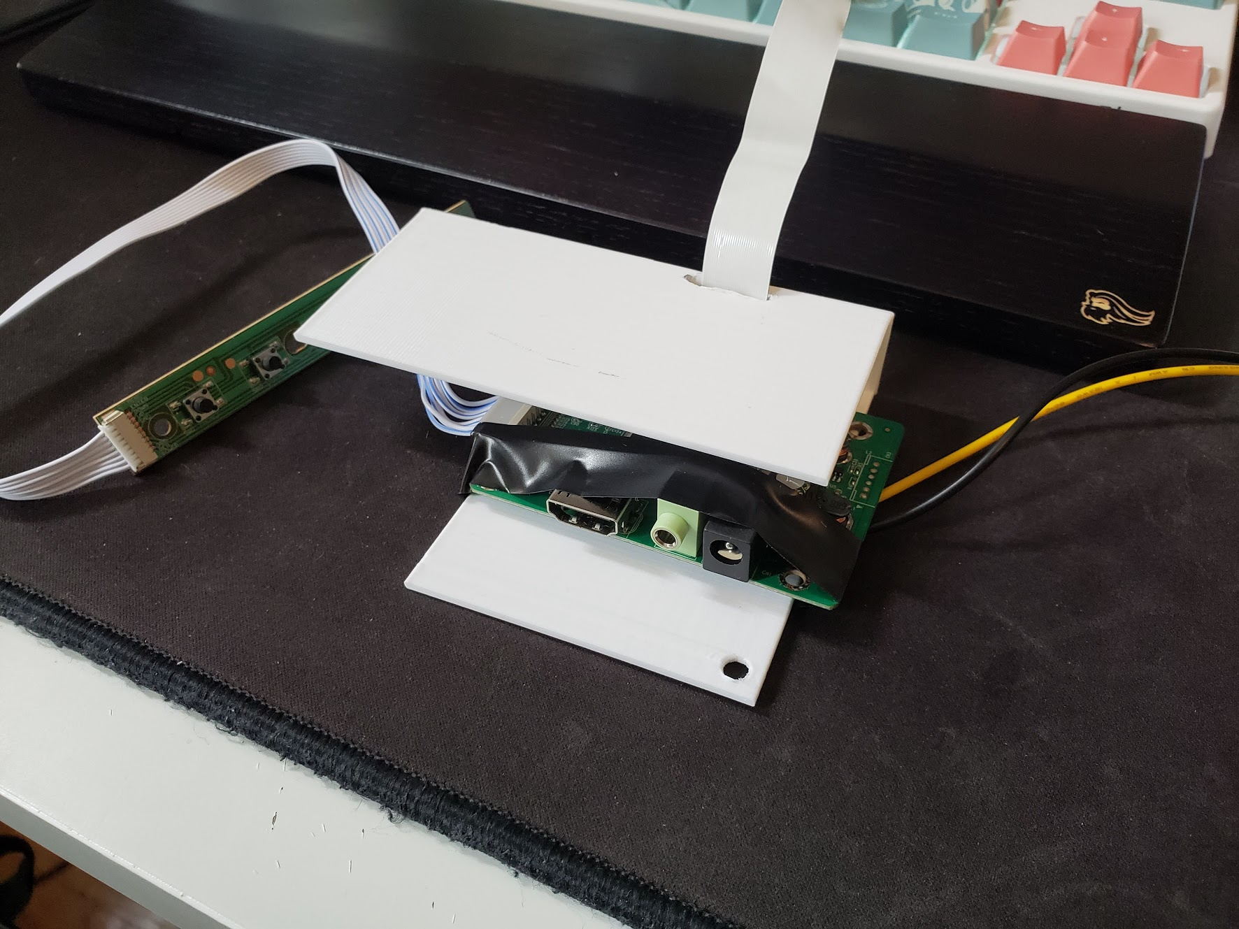
I just wanted to mention how tiny the PCB that’s directly connected to the LCD is compared to my old LCD. So much cleaner. However, since this LCD is a 16:9 aspect ratio it really pushes all the way to the top and bottom edges. That means I can’t mount 2 out of my 4 LED strips on the side panel. I’m planning to mount one of my LEDs strips in the top of the case(which will hopefully light up the top of the noctua cooler - one of the things I overlooked from my v2), but other than another LED strip in the front of the case, I don’t see anywhere else to put the second strip. However, it’s late and that’s work for another day.
Thanks for reading, so far so good!
2020-12-15: LEDs
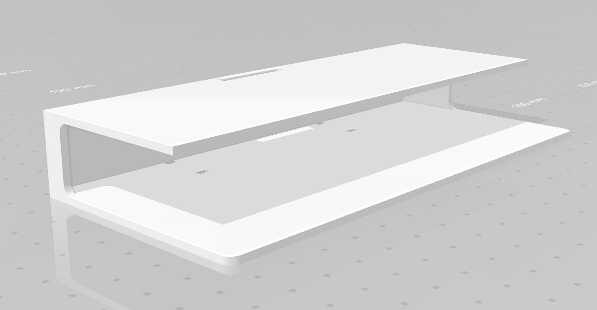
Well before doing the LEDs, I did a quick modification of the display controller shroud. I created an exit hole for the display ribbon with the tip of my soldering iron.
I actually modelled up a new one to get printed at my local library, but they are backed up on 3D print orders so I have no idea when I’ll be able to get it printed.
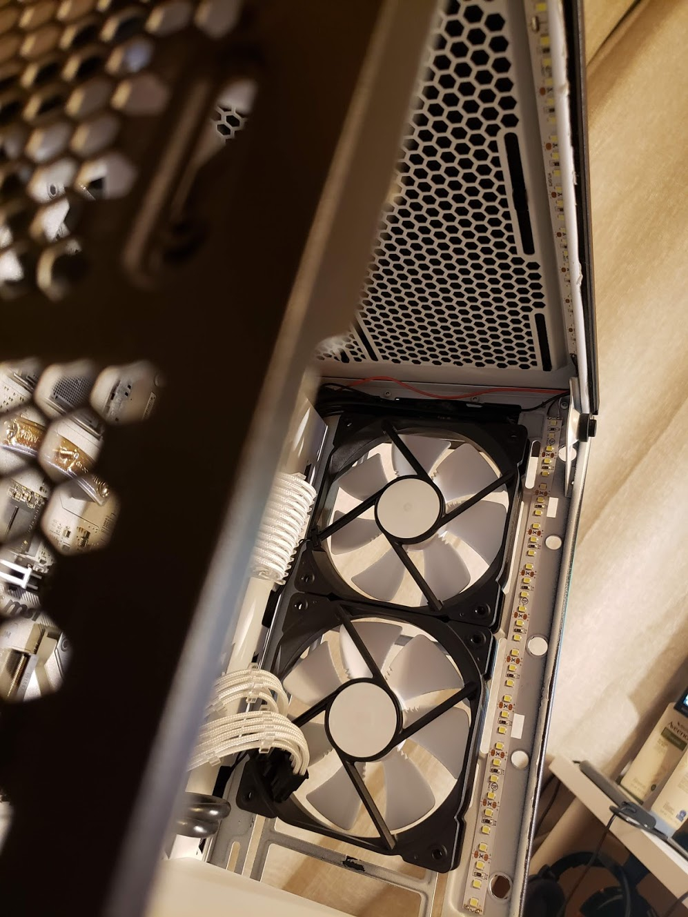
Now the LEDs. One strip on each side of the LCD panel this time, since there’s no space on the top and bottom. Wire fits right underneath the panel, barely squeezing in the gap between the side panel LCD and case…
Did some weird wiring work for the ones that I mounted inside the PC. One strip in the front, one strip on top.
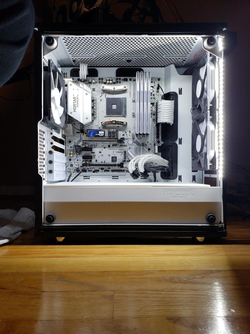
With just the two inside strips, the case is lit up quite a bit!
Gave it a test with the side panel on but not powered. Basically pitched black. Don’t think I’ll be able to see the full effect until after I get my PC built. There’s a bit of light bleed in the front that I need to fix, but other than that it’s looking good.
Now we just need to wait for MSI at this point… Can’t wait!
2020-12-25: MSI finally pulls through
As of late 12/22/2020, MSI finally pushed the beta bios for my motherboard. Awesome! I tried doing usb bios flashback without any CPU installed with no luck. Reading online, apparently the mobo is very picky about using a usb 2.0 drive which I don’t have atm. Took out the 1700X from the B450M Pro4 I was testing with to do a quick bios flash the old fashion way. Worked like a charm after that.
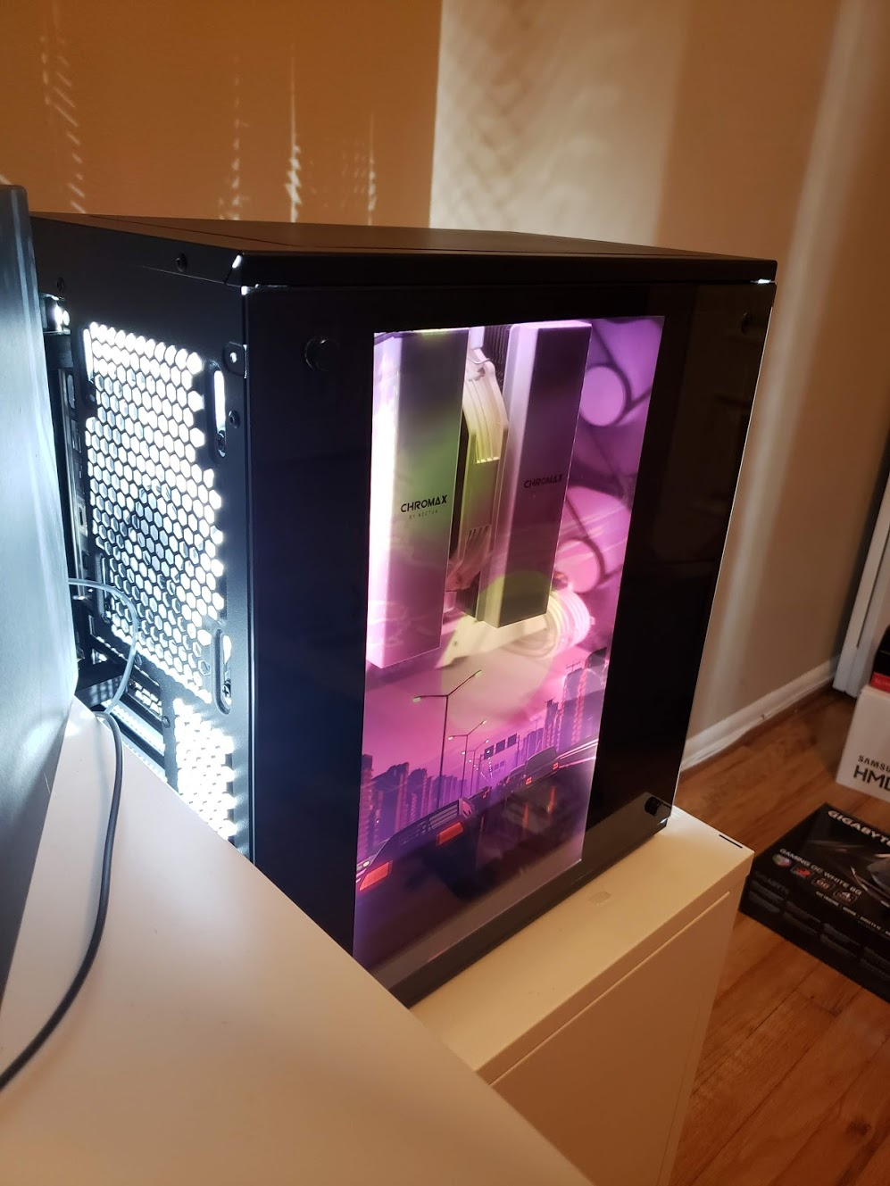
Finally! 5600X in the B450M Mortar Titanium. Literally waited almost 2 weeks for this.
Installed everything back together, and of course it works first try again.
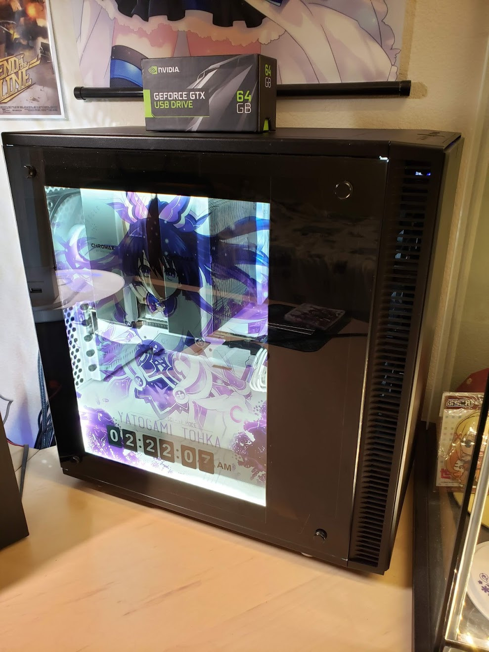
Viewing angles on this panel are very good, especially when compared to the previous LCD I had.
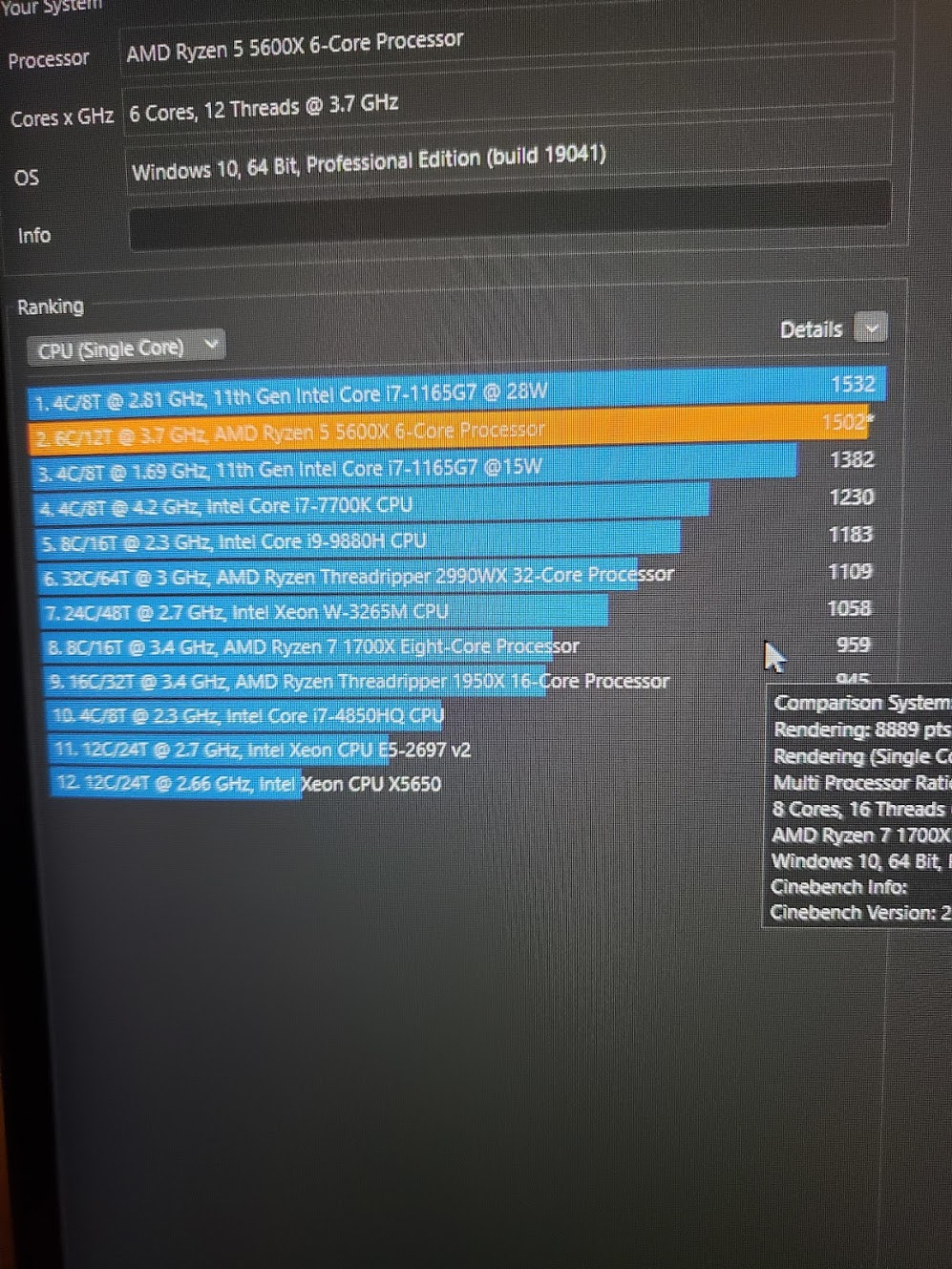
Multicore is insane. Higher performance than my 1700X with 2 less cores. Single core isn’t even comparable.
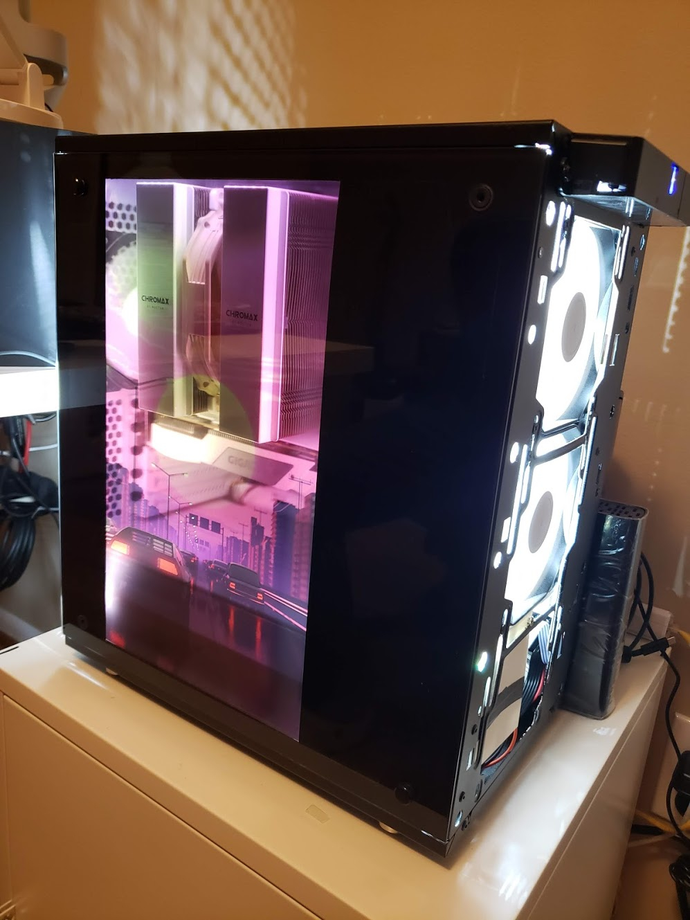
Put back on all the panels and filters.
Sadly with the lack of the LED strip at the very bottom, there’s a rather noticeable dark area now. The CPU Cooler area is a bit better than before with the new LED strip location though, albeit it’s not perfect.
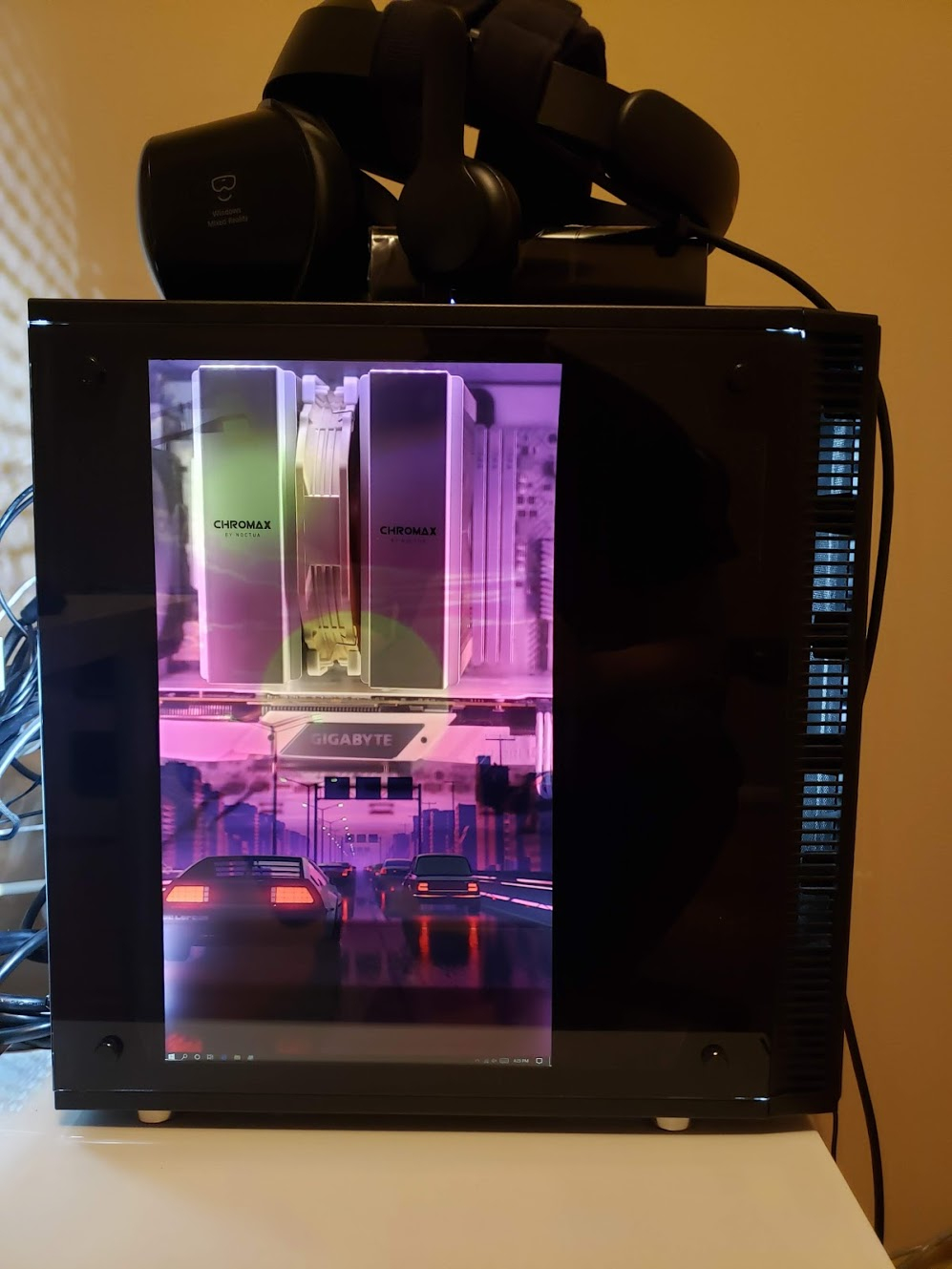
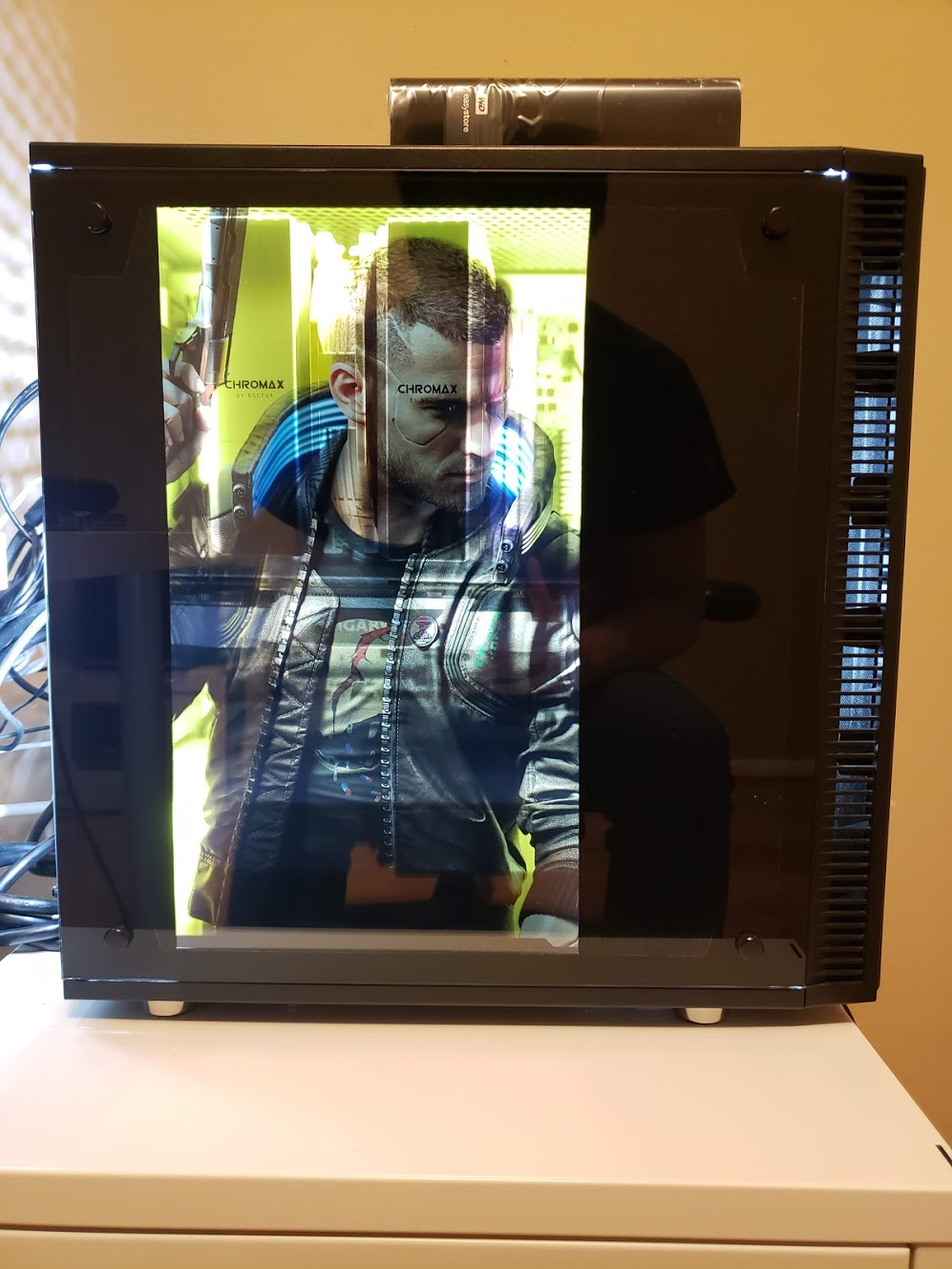
Videos of it in action:


Some more pictures!
That’s it! Internals look the same, but the side panel looks a bit different. Thanks for following along!
well done m8.
This is really neat, but now you must do the needful. Play hentai wafu on it for the memes.
Sorry, this use case is only for my consumption only 
Pinned for a week because it’s badass.
Stunning! Great job!
This transparent LCD stuff is so neat, great work!
I wonder how much you could improve the results with a bit of post-processing of the image displayed, to make the CPU cooler and bottom part less noticeable. I imagine one of two things:
Most likely the best solution is a compromise between the two. The main issue is that such a correction is depended on the viewing angle, but since it is large areas which are close to the panel it might work well.
If you would like to experiment with it but doesn’t know how to do this kind of thing, let me know and I will help you. (Up to the point of converting an image/video with a script, any kind of live correction of the display would be out of scope of what I’m willing to help with.) Just get a way to keep you camera/phone stationary between images, that makes everything much easier.
Hello, thank you for great documentation of your Project!
I’ve done this myself using a Raspberry as host for the side panel, which is remotely accessed through wlan (I don’t like cables going from the outside back in the case again). That’s why I find your solution very interesting.
Can you please explain exactly how you connect and access the Intel mini pc? Which kind of usb cable did you use for example?
Thank you very much.