http://www.amazon.com/dp/B07TD911Y2/?tag=level1techs-20
This is a companion discussion topic for the original entry at https://level1techs.com/video/testing-ryzen-3800x-asrock-taichi-x570-faster-9900k
http://www.amazon.com/dp/B07TD911Y2/?tag=level1techs-20
Already a couple of seconds in…
Where the heck did you get that Picard facepalm bust?!?
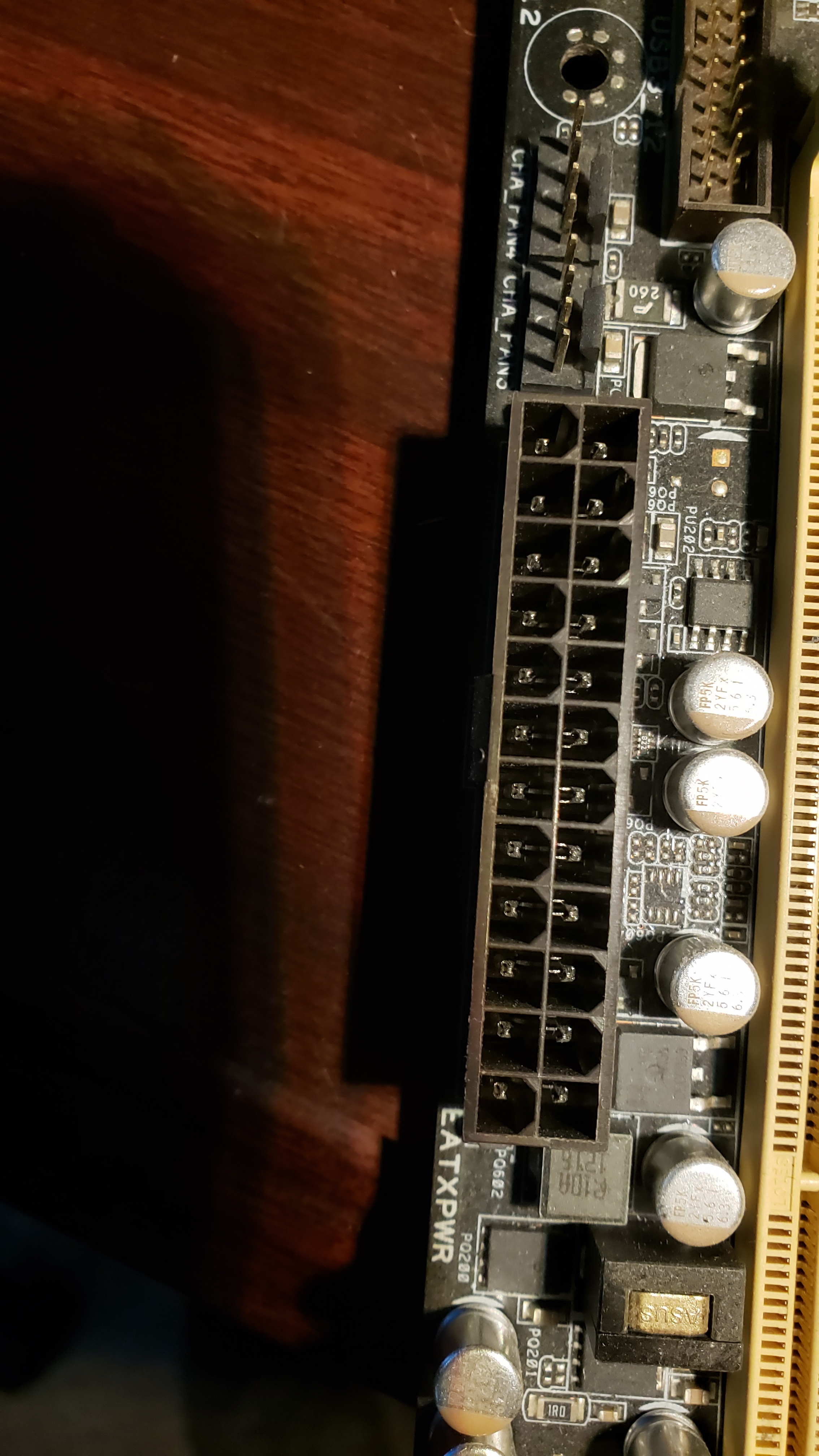
Also, that extra 4pin for the 8+4pin is wired directly into the CPU VRM so it will not help the PCI-E power delivery for the board. Buildzoid can back that up.
Since we’ve both noticed the official Thunderbolt logo is present with this board and not with the Aorus Master, do you expect compatibility to differ, @wendell ?
You also could use a Dark Rock Pro 4 non-TR4 for testing if indeed air coolers cool the non-centered layout of the chiplets better. That has an insane amount of heatpipes.
Yeah, that extra 4-pin will not do anything for the PCIe cards, pretty sure.
I don’t find it strange that a large dual tower air cooler does a better job than an AIO. The latter might look good at first, but the liquid in it will get saturated with heat and then it will be worse than a large air cooler.
It varies from board to board but the 12v CPU Power is connected to 12v power on some boards. Surprised people dont know this
I ended up ordering the Ryzen 3800x due to the lack of stock on the 3700x. One of my friends said it was a waste of an additional $70 since it’s not really any better than the 3700x. What’re your thoughts on this @wendell?
Either way, I felt it was time to upgrade my office rig from an i5-3570k to the new Ryzen series. I’ve opted for the Asus Crosshair VII Hero x470 board so I can still hang onto Windows 8.1. Though I’m seriously starting to consider running Fedora or OpenSuse on the machine, and instead either running Windows 8.1 or Windows 10 within a VM environment on the machine. The only software I actually need Windows for is QuickBooks Enterprise, but enough of that rambling on the system…
I’m more or less curious on how the 3800x will hold up against the 3700x, and I’m hoping I can still benefit from this with the x470 chipset. Unless performance benefits (PCI-e Gen 4.0 aside.) still are ultimately better with the x570 boards?
I know you talked about some optimal settings for the newer ones, but I don’t know if they will come close to apply to the older generation boards or not. I hope I didn’t make an oops with my choice of hardware. lol
Buildzoid might need to do some continuity checks to ensure that’s the case. That might be something he could investigate if he had a ton of motherboards.
the graphs in the video show a 3700x oc matching or in come cases beating a stock 3800x, so that is confirmed.
But the 3700x can’t come close to 4475 1.38v that the 3800x can do. So if you want same perf as OC 3700x with warranty, 3800x. Or if you’re manual OCing, then 3800x has got a lead.
That’s great to hear, because I do want to do some overclocking with it. Will overclocking it on a x470 board be as effective as the x570? Or will it boil down to UEFI updates still?
Thanks! 
I hope the third time is the charme and gets an answer:
Does the Gigabyte Titan Ridge Thunderbolt 3 AIC work in the ASRock X570 Taichi?
uefi updates still pending, there are problems there.
It seems like it does, but more testing is needed. So I’m not sure yet.
Thank you for the feedback, Wendell!
Do you know if there is something “up” with the Gigabyte TItan Ridge AIC (EOL? Design flaw?)?
It completely vanished from European retailers and future availability gets pushed nearly daily.
This majorly vacuums, after 32 GB ECC UDIMMs in general this is the next component I have to rely on for builds that disappeared from the markets 
I really don’t think so. I would think that you would want to keep those power planes separate for obvious reasons? CPU power and PCIe power that is. Or have additional circuitry on the board to keep check? Easy enough to check with a multimeter with the board in hand.
I also would think the motherboard manual would mention something about it, but it doesn’t.
Oh? Can you elaborate? Why don’t you think so?
In the evolution of motherboards it’s been kind of a thing. When ATX was a thing, 5v and 3.3v ruled the roost, so lots of pins there for those voltages, but only 1 12v pin. ATX20 was a single 12v pin!!! ATX24 added one more 12v pin.
I think it might have been true in the 4-pin CPU power days, but it’s waaaaaaaaaaaaaaaaaaaaaaaaaaaaaaaaaaaaaaaaaaaaaaaaaaaaaaaaaaaaaaaaaaaaaaaaaaaaaaaaaaaaaaaaaaaaayyyyyyyy less true today. And there are some boards where it’s still true, and they have auxiliary pcie-style 12v inputs and will use that if you plug it in.
Back to the ATX mob connector. That’s two 12v pins. Where’s the power for 3 75w x16 devices come from then? Two pins won’t do it @ 75w ea…
There are even two physical types of pins that might be in these sockets. The “X” or “U” style pin is only rated for something like 50W IIRC while the solid-core pins are rated for ~75w each. (Breakdown voltage is > 100w so droop creeps in past 75w).
solid core
50w ish max pins
That’s why I usually say like 375w max with 4 pins working in parallel a (Eps12v) and 400w absolute max. And that’s ONLY if I see solid-core pins.
I said this as a throw-away thing, a given, but so many people seem to be militantly wrong about to even consider the logistics. “No you’re wrong” kneejerk vs “actually okay digging into it, it is much more interesting than that in that there are even several kinds of pins that might exist in a same-looking socket. LOLOLOLOLOL?”
Check the atx spec from intel:
There are only 2 pins that can deliver 12v to the motherboard. You mean to tell me those two pins supply 12v for literally everything except the CPU? The math there doesn’t work if you’ve got more than 1.5 GPUs since damn near everything on a motherboard is 12v.
I’ve also had motherboard engineers tell me that this is so, for these reasons, but I’d love to know more about it if there is more to know here about the hows/whys/etc. If you work on power planes or motherboard engineering or something and can fill in some gaps here, though, that would be nice?
I don’t work on motherboard engineering, just have an engineering background and an interest in computer parts. Been a long time now since I studied electrical engineering and actually did work. Somebody like Buildzoid could probably give a much better answer, problem would be for us mere mortals to understand it. I would love an at length explanation for sure though. I also do love to dig into stuff so let me spill out some of my thoughts.
I’ve just never seen +12V connectors on top of the board that supply voltage to the PCIe slots, but I guess it would be possible? Just impractical and expensive to run a power plane for the PCIe all the way from up top down to the slots (extra layer in the PCB maybe?). Extra power connectors for the PCIe are usually near the PCIe slots, also they’re pretty much never EPS 8 or 4-pin but PCIe 6-pin connectors (or the terrible old 4-pin hdd power, bleh). And as I said, with the board in hand it would be very easy to check with a multi-meter if the the top 8-pin or 4-pin connectors are connected to the PCIe slots.
It would make sense for say the MSI X570 Godlike to have one of the top 8-pins wired into the PCIe as it has four full length PCIe slots. One 8-pin for the CPU should be plenty anyway. The Taichi only has three full length slots, plug in three Rx480’s and watch if the 24-pin melts?
What I think is a problem is mixing the power planes together. Random PCIe card loads the +12V power plane and makes the input to the CPU VRM dip ever so slightly making it scramble to maintain stable CPU voltage. I’m not really an electrical engineer, but that sounds to me like much more trouble than it is worth. But maybe some actual Eeng can weigh in and set me straight? Maybe some filter circuits makes sense on a more expensive board.
Yes, I think so. Memory could possibly be on CPU power too, but I don’t think it is (DDR4 doesn’t use much power anyway, I think memory VRM run on the +3.3V). Everything but the CPU off the 24-pin and ofc it can be a problem.
This has been the case for as long as I can remember ATX was a thing at all. AT connectors were different, remember how it was possible to put them in wrong and fry the mobo? Those were the times…
It is kinda hard to find PCIe cards that use the full 75 Watt power from the PCIe slot. The Rx480 was quite the unusual thing in that department. Mining with 1x to 16x adapters without extra power connectors comes to mind for burning out the 24-pin power pins. Boards advertising 4-way SLI usually had an extra PCIe power connector for the slots.
Remember that only the full 16x slots get the 75W power budget for full length cards, shorter cards only get 25W IIRC. And that is +12V and +3.3V combined, max 66W from +12V. 1.5 full power GPU would be 99W from the +12V. Most GPUs don’t use the full 75W from the slot, several people have tested this. PCPer had a rig especially for this back when the great PCIe power debate raged around the Rx480. Others have done similar things. A 1080ti reference for example draws about 50W from the slot +12V (my Strix card uses about 30W). Four cards using 5.5A on the +12V would mean the end the 24-pin (22A on just two pins, way over the allowed 16A), but then again motherboards that support 4-way SLI usually have an auxiliary PCIe power connector on the board for the slots. That the MSI X570 Godlike doesn’t seems strange, again it would make sense for one (or why not both) of those top 8-pins to be wired into the PCIe too.
Far from everything on the motherboard is +12V. Quite a few things use the +3.3V (PCIe , chipset etc) and the several +5V pins (USB for example). Those Dell, LG etc boards that only take +12V have buck converters to get the lower voltages, not needed on a consumer ATX board as +5V and +3.3V come provided in the 24-pin. I actually think it is mostly, if not only, the PCIe that uses the +12V from the 24-pin. What else is there that uses +12V instead of +3.3 or +5 Volt?
This also leads us to power per pin in the 24-pin. Molex spec:
https://www.molex.com/pdm_docs/ps/PS-45750-001.pdf#page=6
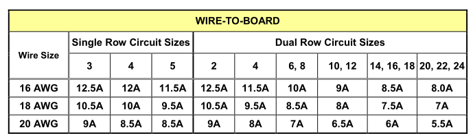
Maxing out at 8A per pin, or 96W at +12V. And that is for std pins, solid ones would probably be more. Why a std 8-pin CPU power can do 384W of power and why you usually don’t need more than one 8-pin on an AM4 board for the CPU.
Having the extra connector for PCIe slot power at the top of the board instead of somewhere else probably more inconvenient is a good thing I think. I for one welcome our new EPS powered PCIe slot Overlords.
Yes that´s what it is initially ment for.
Those are most of the time either 6 pin pci-e power connectors.
12V cpu power connectors are wired into the cpu power plant.
Or to me more specific into the powerstages,
and in the old days the highside mosfets with an discrete mosfet setup.
Thats why you call them the highside mosfets.
It might be that some of the 12V power lines are also wired into other,
area’s of some boards now days.
But i have not measured that lately.
And it´s kinda hard for me to do, since i only have one X99 board laying around atm.
I would understand it. I’ve heard him say that the EPS12v connections supply only CPU power which I know to be incorrect on at least some contemporary motherboards.
Length of the wire is not a good argument to make. If you look at the straight-line distance from the top of the board eps12v lines to the leftmost part of the PCIe slots, and from the ATX 24 pin 12v lines, the length is about the same, if not longer from the ATX24 side. The Vregs come down the left hand side of the board on many boards, certainly AM4, almost to the first PCIE slot. So we’re talking about an actually very tiny amount of copper.
The boards for sure do need at least 1 of the 2 12v lines. It seems like the management bus and stuff like that are isolated 12v setups from the rest of the system, so you’ll need the lines to post… butt…
This is only true in desktops, not servers. Servers for sure mix their EPS CPU and PCIe rails too, though some don’t. And have extra EPS12v connectors.
Yep, this is the case. BEEEEEEEEEP. For this particular board anyway.
The 1060/1070 also draws kind of a lot of power from the slot. I have some PCIe storage devices that also use a lot of power. There is a bit of a negotiation process to move from 35w (25w in old days) to 75w iirc anyway.
I believe this was the original spec, and the the combined limit is still 75w but the limit for 12v alone was bumped to 6.5a from 5.5a. Oh, and the GT 7300 was the first card to take advantage of this bump IIRC, it was a card using ~70w on the 12v rail. These cards mostly do their own regulation except for a very little bit of 3.3v logic to handshake to get into high power mode.
But yes, those are within the numbers I already quoted.
12v fan headers, memory, etc. The RGB LEDs and usb use 5v, some glue logic stuff is 3.3v but almost everything else is using the 12v rail and stepping down to low voltage at lots of current. The chipset is almost certainly using the 12v rail, maybe not, but it’s the same lithography process as the iodie, and that probably wants around 1v operating voltage.
I do not believe that just two 12 pin lines would be sufficient for two high current devices on the motherboard, plus fans pumps, chipsets, etc.
10a for cards, 3a for fans and various other 12v bits, memory, chipset, other 25/35w addin cards etc fit in the last 3a? No. The taichi is a 3x16 slot motherboard, so it has to draw from somewhere.
Besides, if your power stage design is such that you have a multi-rail power supply and the board designer assumes each 12v input is a different rail then droop on one rail is more easily compensated from another rail. SSI spec talks about that a bit…
This is incorrect, solid ones are the 96w ones. They are prettymuch the standard now, but not always. I do see them mixed on cost down boards. The original spec was 7a = 336w for the 8-pin connector, which is around the number buildzoid usually quotes as the “safe” number IIRc.
Several things I said are in the reference spec:
8a per pin, etc, whichj I think we agree on.
Not all cases the CPU power is mixed, but in this case it seems to be. I generally assume that is true when I see two+ PCIe x16 slots plus a lot of 12v “gravy” like a bunch of high-current fan headers for pumps and whatever.
The easiest way to check is doing a continuity check on the 12V line between the 24pin ATX and the 8+4 pin EPS/ATX power. If the multimeter doesn’t beep, it’s not connected.
not the atx24 pin 12v, the pcieslot 12v, its got to be connected to at least one of them. In this case not the atx24 but the eps12v.
Yeah this could be very well the case,
that some of the 12V line from the eps cpu power connectors,
gets wired into other area´s of certain boards now days.
I have not really measured that lately.
In the old days i don´t really think that it was the case.
Except for certain server boards maybe.