Alright, my vacation is over. I stopped updating this work log and instead focused on getting as much done with the limited time I had.
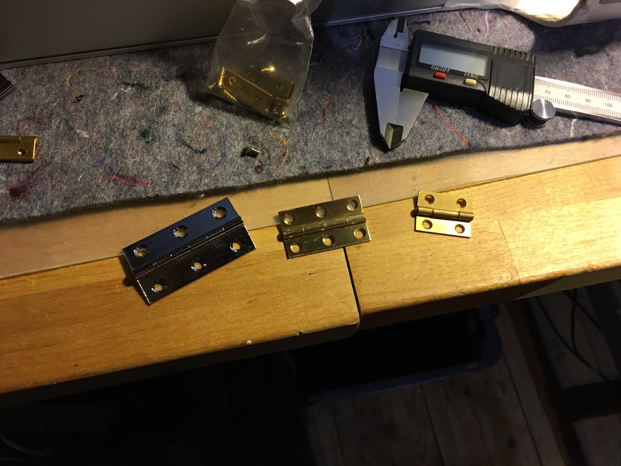
Here’s how I solved the PSU mounting problem. My dad gave me an idea of making separate tray or “sled” for the PSU, that can be pulled out entirely from the case. This was much simpler solution than what I had in mind. Idea is to have some surface where the PSU can rest on. Dad also suggested I could use some spare hinges he had lying around to make using the PSU tray even easier, but unfortunately I didn’t have enough space to cut big enough hole for the PSU so this idea had to be scrapped. I just attached the tray with nuts and bolts.
After I got the PSU tray done I realized other than bolts and nuts every piece of aluminium I used were recycled scraps from my past case projects. 
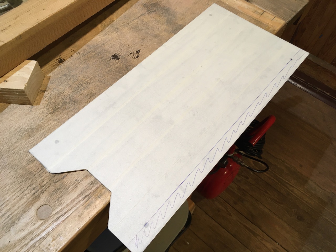
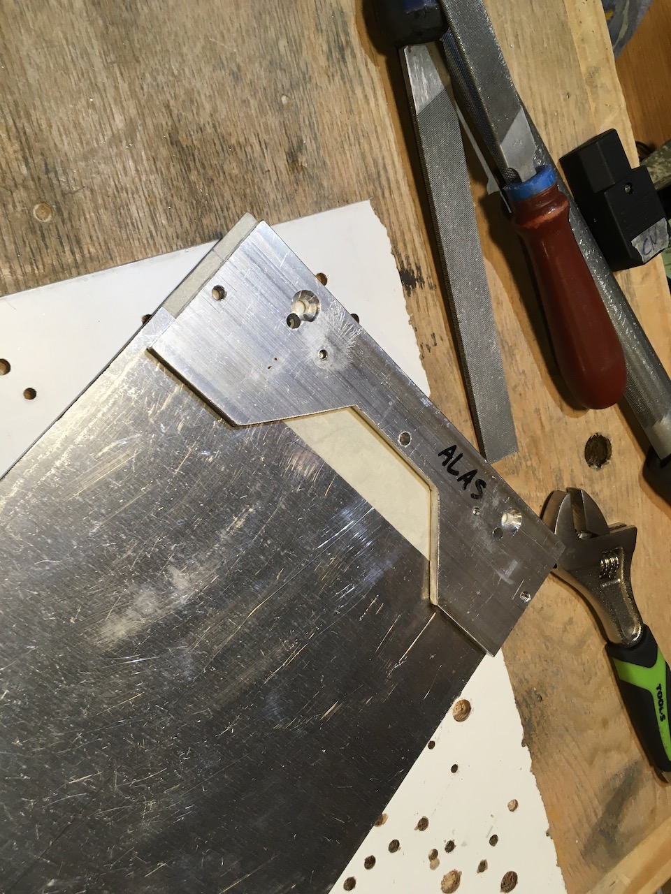
For example this piece I used as a base for the tray is the old prototype front panel from my previous case project. Just need to trim off some excess material.
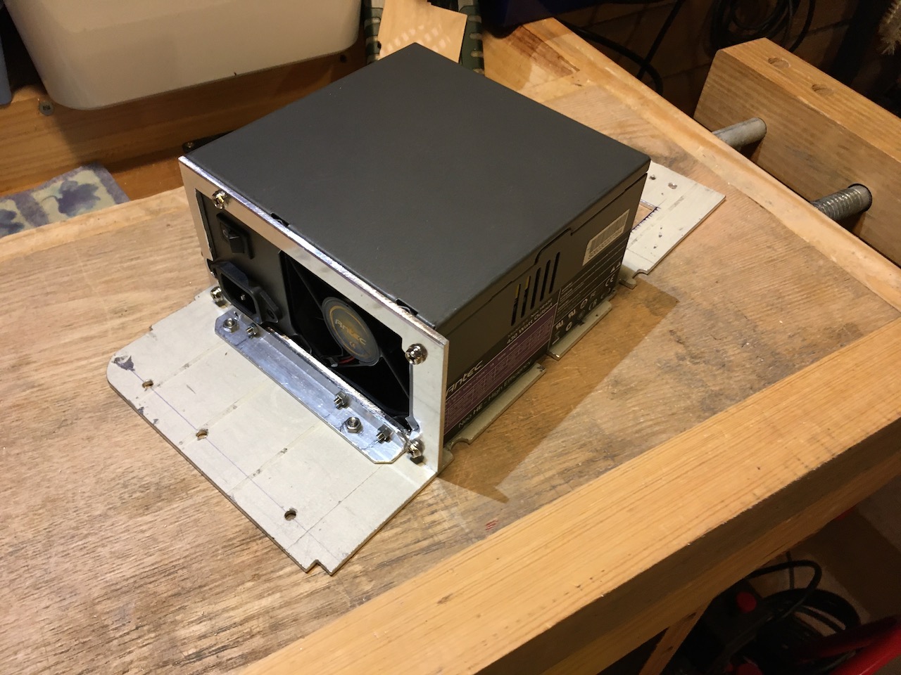
I also made small mounting shroud for the PSU. Since the PSU will rest on the tray, I could have used just some simple L-profile, drilled holes that I can attach the PSU using the bottom row mounting screws and call it a day, but I wanted something little more robust.
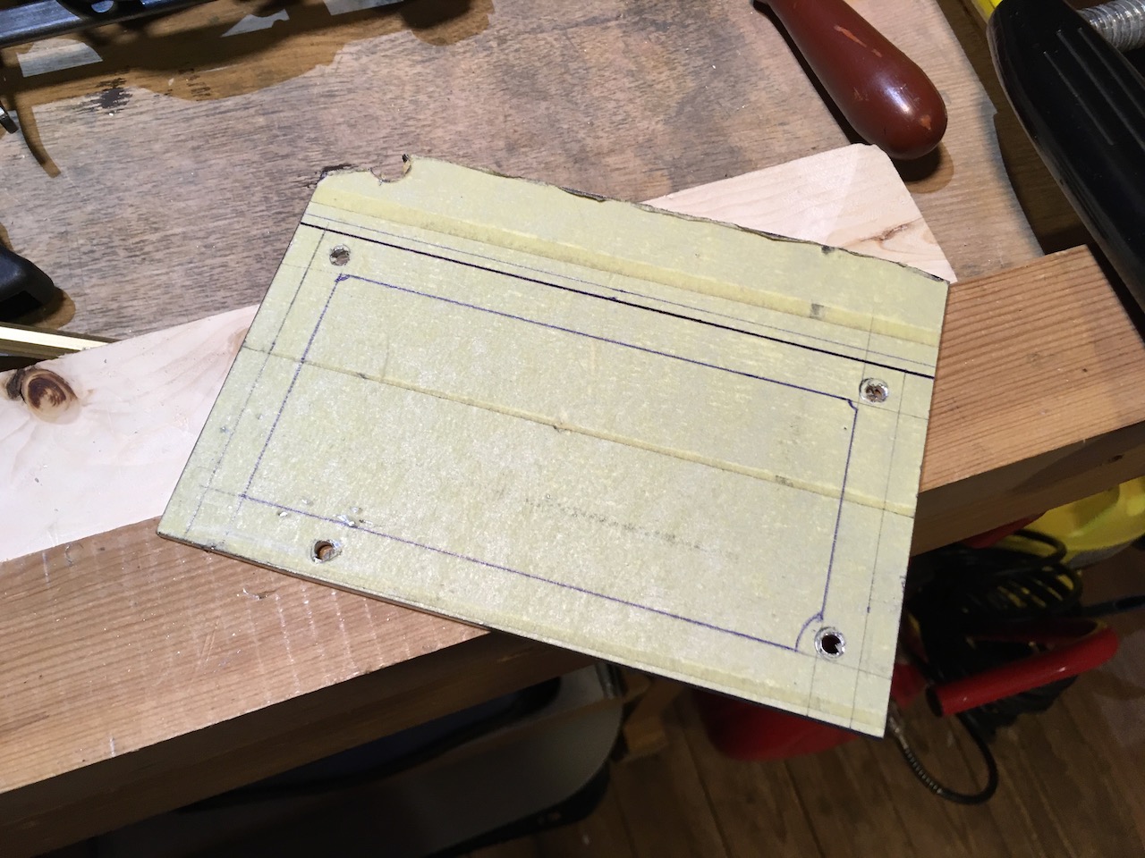
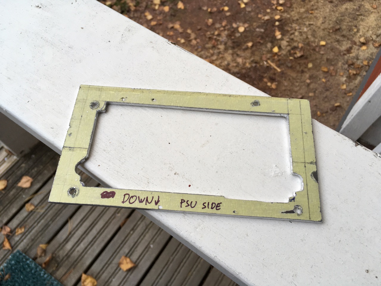
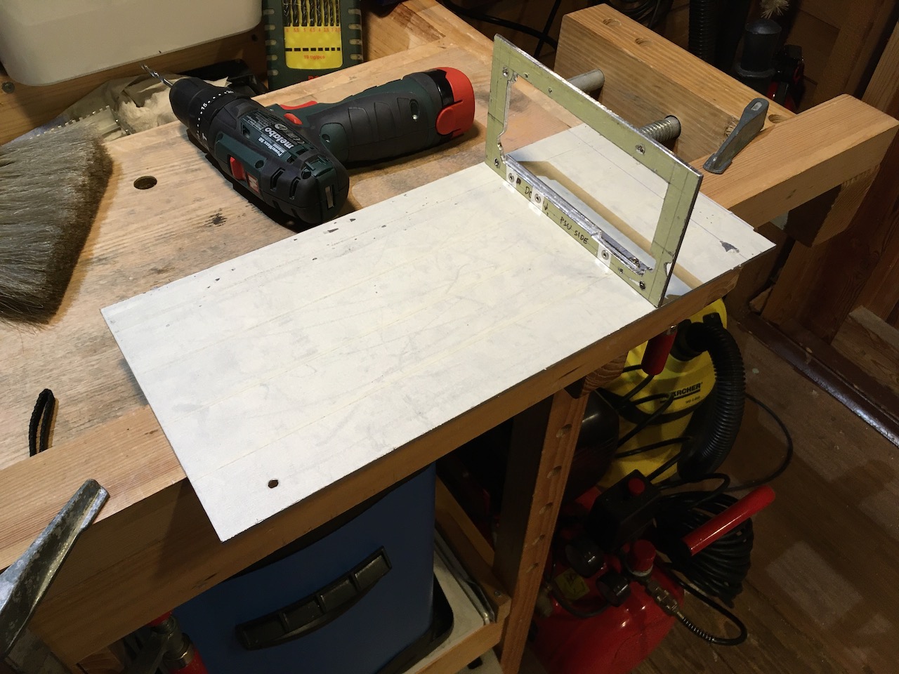
I did trim off some excess material from the PSU shroud later, but for now I just wanted to see if the thing fit’s into the G5 case.
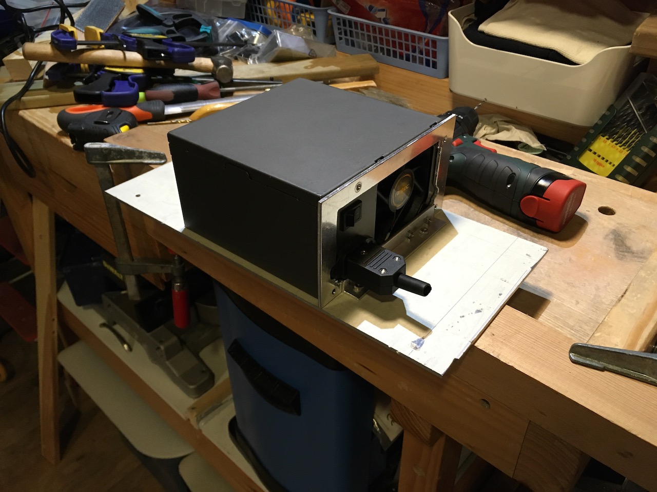
I also had to make some adjustments to make sure the side panel locking mechanism has enough space to move.
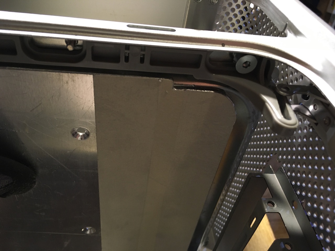
And then it was time to drill holes and attach the PSU tray to the original divider plate.

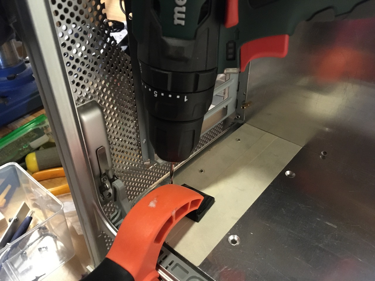
I didn’t have clear idea how big hole I had to cut to the divider plate, so I cut several pieces until I was finally able to fit both the PSU and PSU cables through the plate.
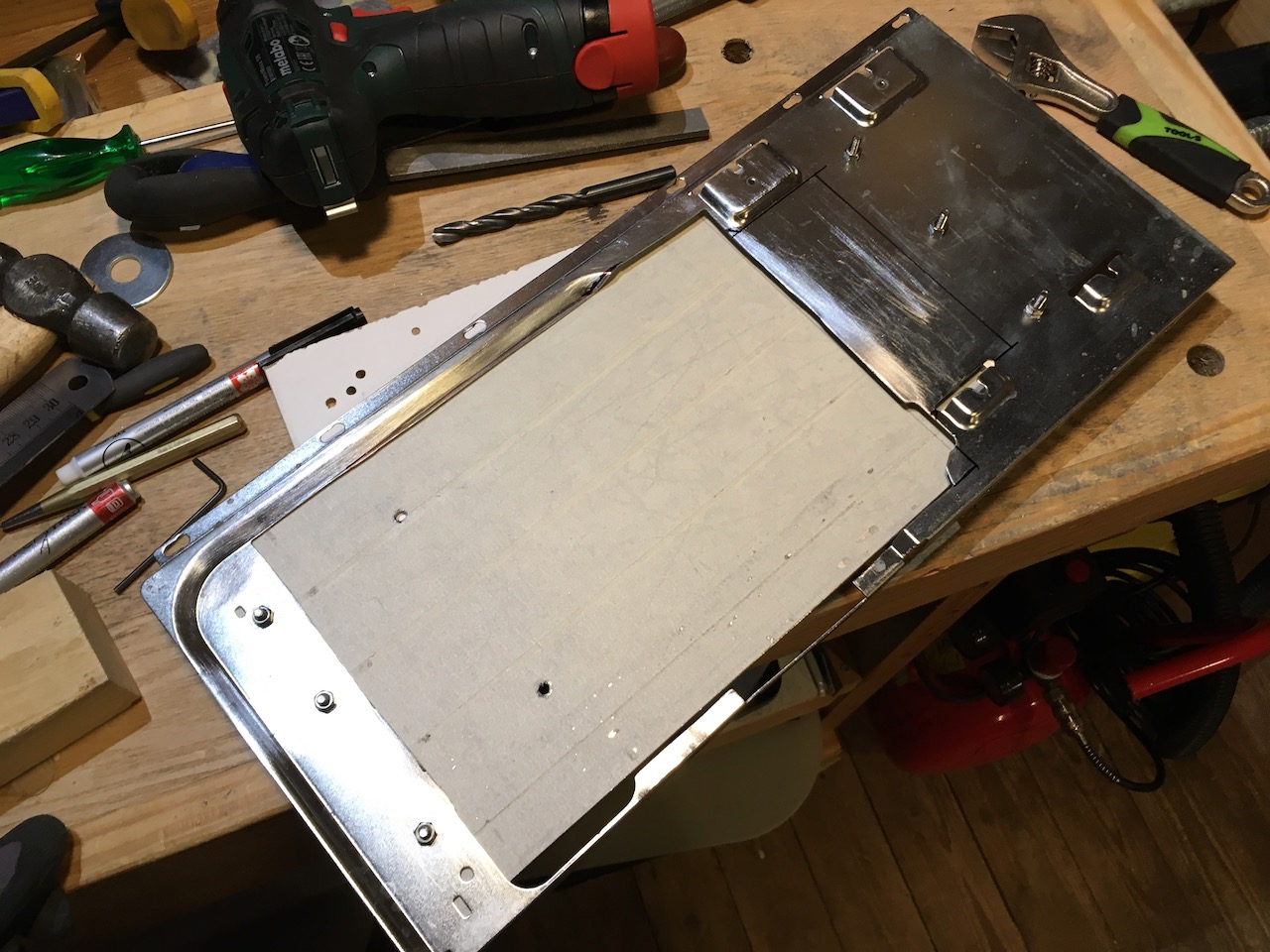
There’s also small roughly 5mm height difference in between front and back of the divider plate, so I had to make some spacer to make up for that. Ended up using one of my failed attempts at making case feet to my previous project, hence the shape and unnecessary screw holes in the spacer. This piece won’t be visible once the PSU tray is installed so meh, didn’t really care how good or bad the spacer looks.
And here you can see the final hole in the original G5 divider plate.

Then the last thing to do was to cut holes to the PSU tray. One hole for the PSU cooling fan, and another hole where I will route the PCI-e, SATA and other power cables. I used old 140mm fan to eyeball where the PSU cooling fan might be.
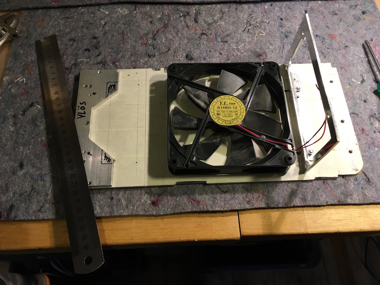
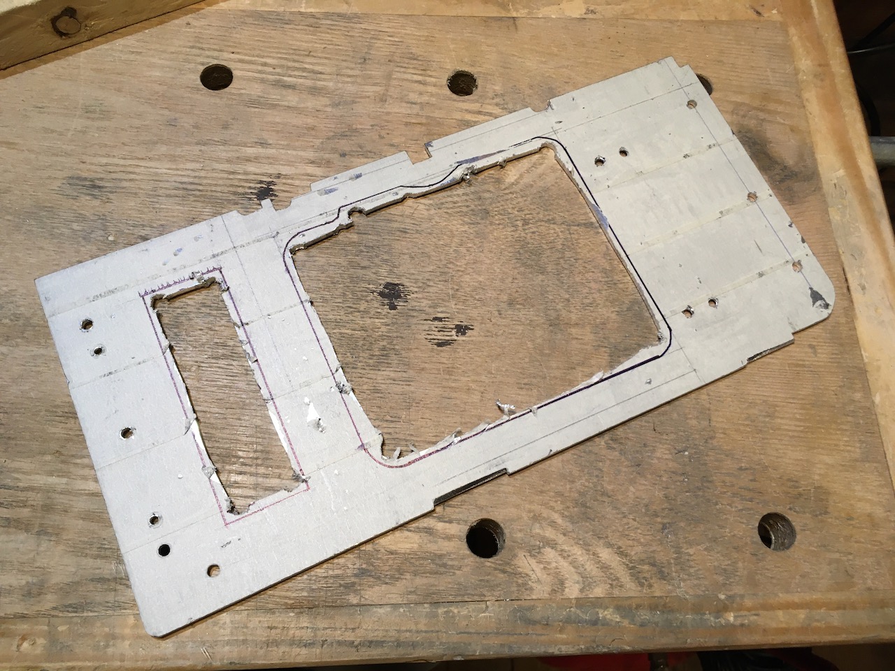
Fan hole is bit oddly shaped because I wanted to leave some material to the tray, to make sure this thing can support the weight of the PSU. Those weird notches on the left side of the tray are for the screws and motherboard stand offs. Without them I can’t slide the PSU tray to it’s place.

I also cleaned the PSU mounting shroud. I don’t like using L-profile attaching things because it looks bit ugly imo, but right now I didn’t care that much.
Front hole is for the power cables. That tape on the PSU says “fan” in Finnish. I don’t have dead PSU that has bottom exhaust fan so to make sure I remember which side the fan is on modern PSUs I had to mark it some how.

Here you can see better why I had to make those odd notches to the side of the tray.
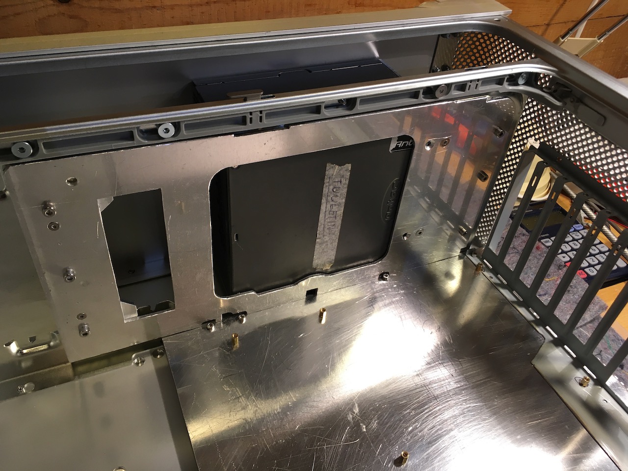
One last cut to the original divider plate. I cut little bit off from the corner to make sure I can fit the power cord here. I’ll show later how the power cord will be routed from the back of the case to the PSU.
Oh and those original stand offs were removed later.
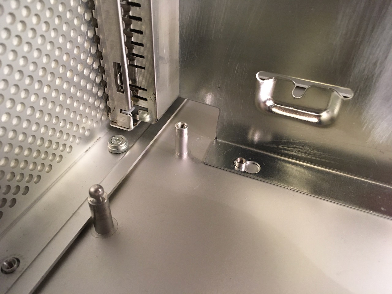
That’s it. I’ll update the front fan mounting bracket and internal power cord next once I find some extra time to sort out pictures.