While I know everybody wants to dive right into satellite communications theory as per my poll.
I think radio propagation theory is important to first cover. These series of posts will generally be from my own knowledge. The exception largely will be pictures or graphics. I do not intend to reinvent the wheel unless I have to.
Disclaimer: I do this purely out of self motivation to have more “tech geeks” informed about radio theory. It can and may help you avoid making silly purchases when it comes to various wireless equipment which includes but is not limited to routers (i.e a gaming router with claims to have 5x the throughput due to 2x the transmit power and qos prioritization<-- LOL)
This is also intended on being a reference when I mention a term in later overviews that confuses you like reflection or reflected energy etc. The intent is so that you may reference or ask questions for further depth should you want to know.
People who voted in the poll are tagged as followed  : @BookrV @Adubs @MazeFrame @nx2l
and tagging for the sake of bingo: @SgtAwesomesauce
People who were interested in affiliated posts. I will mention you as a courtesy
@anon85933304 @KenPC @Hadesfriend @psycho_666 @mutation666
Radio Wave Propagation Theory
Essentially what we are going to discuss is how radio waves travel from one point to another through whatever medium they might encounter. Just like light waves or other forms of electromagnetic radiation, radio waves are affected by several phenomena. I would say this list is quite extensive but it can be summed under the following: reflection, refraction, diffraction, absorption, polarization, and scattering. Commonly known to us from taking tests on it as 2R-D.A.P.S. (a way to memorize them).
The Basics
The mechanisms and laws of radio waves largely come from basic trigonometry, Maxwell’s Equations and Fresnel’s Equations. These bodies of laws make up what physicists and engineers call the basics of classical electrodynamics.
Here is some TL:DR nitty gritty. You may skip this if you don’t want to read it as you have the basic principles demonstrated already. Basically light and radio waves are electromagnetic waves which behave largely according to maxwell’s equations. Let’s dive into some math for those who wish to know. Bear in mind this requires calculus knowledge. While I cannot explain that all right here right now, http://tutorial.math.lamar.edu/ should be able to give you some cheat sheets to figure out what I am performing. Let us start with a chart of their forms

(HAHA cool that showed up right… Win for Tex image charts)
These laws come in two primary forms. Differential and Integral. For the purposes of this post I am not going to cover the why behind this. Though the easiest laymans explanation is that “it depends on what your doing”.
Now we take all four forms of the laws and we attempt to assemble them to make a wave. Instead of writing it out on paper I chose to use LaTEX/MathJAX since this forum is kind enough to implement it. Steps are skipped we do not need pages of math. Ive chosen a font closer to my own hand however the symbols should retain familiarity. In my math I denote multiplication with no space as dot will indicate a dot product
Let us imagine a region of free space where the electric field \large \mathcal{ E(x) \ne 0 } along the z axis in a Cartesian coordinate system. The magnetic field \large \mathcal{B(x) \ne 0} along the y axis. \large \mathcal{E(x)} and \large \mathcal{B(x)} are both functions of x only.
As it happens when we do this Faraday law of induction gives simplifies to:
\Large \mathcal{ \frac {\partial E}{\partial x} = - \frac {\partial B}{\partial t}}
Amperes law is modified to the following due to the current density \large \mathcal{J = 0} which is obvious. We are not transferring current in the air only voltage. (current can transfer in air you see it with lightning).
So now we have: \Large \mathcal{\frac {\partial B}{\partial x} = -\frac{1}{c^2} \frac {\partial E}{\partial t}}
In order to obtain the wave equation we must take the first equation with respect to \mathcal{x} and the second equation with respect to \mathcal{t}.
Math:
\Large \mathcal{\frac{\partial^2 E}{\partial x^2}=-\frac{\partial^2 B}{\partial t^2 \partial x}}
* at this point you should see that we can use some substitution to manipulate the equation as we need it to be
\ \ \ \ \ \ \ \ \ \ \ \ \ \ \ \ \ \ \ \ \ \ \ \ \ \ \ \ \ \ \ \ \ \ \ \ \ \ \ \Rightarrow
\Large \mathcal{-\frac{1}{c^2} \frac {\partial^2 E}{\partial t^2}=\frac{\partial^2 B}{\partial t^2 \partial x} \therefore \frac{\partial^2 E}{\partial x^2} = -\frac{1}{c^2} \frac {\partial^2 E}{\partial t^2}}
See something peculiar about the equation. We have essentially derived the wave mechanical equation however in electrical form. This results in a wave form that is a set of linear combinations of sines and cosines. We as engineers are able to use the Fourier transform to show this linear combination (topic for another day) LINK for those with morbid curiosity . Here is a visual below.

Notice B is the magnetic component on the y axis and the electrical component is on the x axis. This is very important to modulation later. I have put together a graphic thats transparent and animated for you in MATLAB. The wavelength is related to the frequency of the wave and is represented by \lambda
That cool property you are witnessing here in my graphic where they do not interfere with each other is called Orthogonality.
I think we have exhausted the basics
Reflection and Refraction
Let us begin with reflection. We probably already are well experienced in this with light. We have mirrors in our own home and this is a good way to examine reflection as radio waves are not tangible however they do react similarly. The reflection of light falls into two categories. Specular reflection is a mirror like and diffuse reflection retains the energy but you do loose the image. This is sort of the same thing with radio waves. They propagate and either their reflections are constructive (specular) or destructive (diffuse). This causes radio wave refraction. Often people associate it as the same thing however refraction differs as this phenomenon is the resulting change in the direction of a wave passing through an objective with different refractive coefficients. It is similar to reflection as reflection they both can be destructive however only reflection maybe constructive (though it normally isnt). I have represented them both in the figure below. Thank you electronic-notes.com for a wonderful base template to make this graphic.
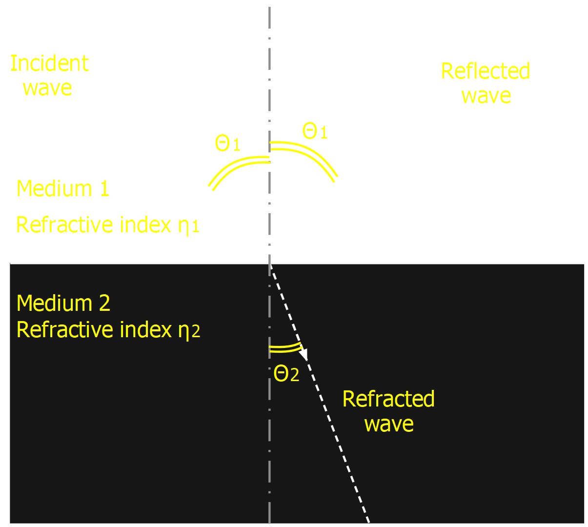
I hope my graphics show up correctly
As you can see this is light however radio waves do they same thing. If you enter a medium that has a different refractive index. The reflected wave is dotted moving upwards after hitting the medium. Here is a visual example
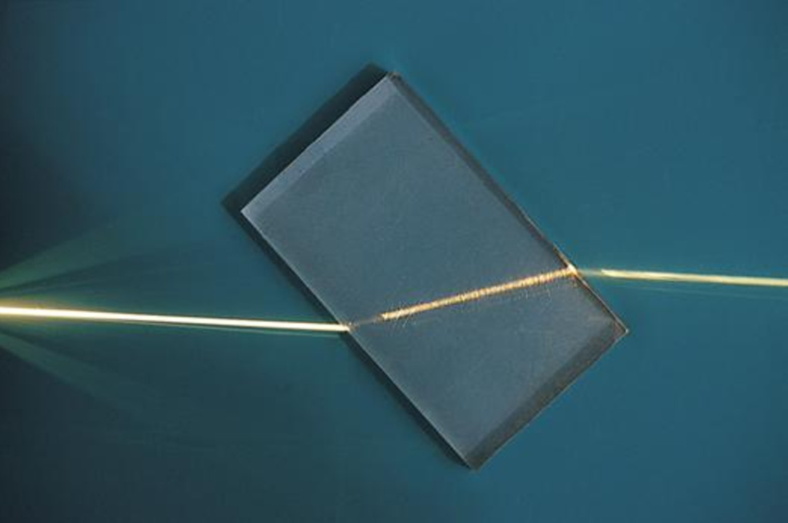
Source: Wikipedia
Here is a lovely animated wave front graphic of the same phenomenon

Source: Wikipedia
In radio waves this affects both the phase and amplitude of the signal. This is not what is being seen in the animated graphic. That is diffraction in the seafoam green side.
The Law of Refraction determines the refractive index of a material. As it happens both the refractive index and the phase velocity of a wave are related to the speed of light \mathcal{c}. It just so happens the refractive index \mathcal{n=\frac{c}{v}} and in optics we represent it as an angular ratio of different refractivities. \mathcal{n_1 sin(\theta_1)=n_2sin(\theta_2)}
Diffusion is a phenomenon often mistaked with dispersion. However it differs as its primary caused by reflection of different incidents causing scattering. We will get into this later.
Refraction is responsible for dispersion of signals which occurs both in radio and in fiber optics.
Diffraction
Diffraction is actually a group of occurrences that happen after a radio wave encounters something that reflects 100 percent of it but seemingly has a hole in it. i.e the material is radio opaque but there’s a geometrical hole in it. It is defined as the bending of radio waves around the corners of an obstacle or also through an aperture into the region of geometrical shadow of the obstacle/aperture. The corners are far more diffuse where a single source like an aperture will be more defined The diffracting object or aperture effectively becomes a secondary source or sources of the propagating wave. This can contribute to constructive or de-constructive/destructive interference. If people become more interested in fiber optics I will go more into the propagation and diffraction of a laser beam.
Absorption
Absorption though simple in concept is a difficult concept to grasp. This is because light energy is actually undergoing major transformations. One transformation that can occur is that the medium that the photon or EM wave passes through is transformed to the radioactive energy of that medium by means of taking away all excess energy surrounding the mediums emission. We talk about black bodies and they are defined by how much absorption they exhibit. This is a very interesting side of physics and has an affect on channel attenuation though not as significantly. Over sea links have to deal with these more than terrestrial.
Polarization
Polarization is a very important concept in radio waves. In a transverse wave, the direction of the oscillation is perpendicular to the direction of motion of the wave. However it only occurs in non longitudinal transverse waves. It wont occur in sound for example. An electromagnetic wave such as radio waves consists of a coupled oscillating electric field and magnetic field which are always perpendicular; by convention, the “polarization” of radio waves refers to the direction of the electric field. In linear polarization, the fields oscillate in a single direction. In circular or elliptical polarization, the fields rotate at a constant rate in a plane as the wave travels. The rotation can have two possible directions; if the fields rotate in a right hand sense with respect to the direction of wave travel, it is called right circular polarization, while if the fields rotate in a left hand sense, it is called left circular polarization. We often use phase to create the circular polarization. This is important to your GPS signals. We will get into that in future posts.
Scattering
Scattering is a radio wave phenomenon in which the waves are forced to deviate from a trajectory by one or more paths due to localized non-uniformity (often called reflectors) in the medium through which they pass (Often called the channel). In conventional use, this also includes deviation of reflected radiation from the angle predicted by the law of reflection. Reflections that undergo scattering are often called diffuse reflections and perfect reflections are called specular (mirror-like) reflections.
Let’s get radio specific
Now that we have covered all basic phenomenon of propagation lets start getting more radio specific. I will also to an extent cover some of the types of propagation.
In any channel reflection, refraction and diffraction may occur due to reflectors. The resulting radio signal may also be a combination of several signals that have traveled by different paths. This is called multi-path propagation and its an inevitable part of the signal. As an engineer or radio technician you simply have to accept it and work with it. These reflections may add together or subtract from one another, and in addition to this the signals traveling via different paths may be time delayed causing distorting of the resultant signal. It is therefore very important to know the likely radio propagation characteristics that are likely to prevail.
Distance
The distances over which radio signals may propagate varies considerably. For some radio communications applications only a short range may be needed and usually the antenna suits the distance of the transmission. For example a Wi-Fi link may only need to be established over a distance of a few meters and so uses an omni-directional antenna. This is in contrast to a short wave broadcast station, or a satellite link would need the radio waves to travel over much greater distances and even through different mediums and medium densities. Even for these last two examples of the short wave broadcast station and the satellite link, the radio propagation characteristics would be completely different, the signals reaching their final destinations having been affected in very different ways by the channel they traveled through.
Types of propagation
We have various ways we can actually send these waves (propagate them).
-
Free Space Propagation- The radio waves travel in free space, or away from other objects which influence the way in which they travel. It is only the distance from the source which affects the way in which the signal strength reduces. ALL RADIO systems experience this in some form
-
Tropospheric Propagation- Here the signals are influenced by the variations of refractive index in the troposphere just above the earth’s surface. Tropospheric radio propagation is often the means by which signals at VHF and above are heard over extended distances
-
Ground Wave Propagation- When signals travel via the ground wave they are modified by the ground or terrain over which they travel.
-
Ionospheric Propagation- Here the radio signals are modified and influenced by a region high in the earth’s atmosphere known as the ionosphere. This form of radio propagation is used by radio communications systems that transmit on the HF or short wave bands. Using this form of propagation, stations may be heard from the other side of the globe. Yes this is basically what HAARP is.
If you have questions about the following: Sporadic E, Near Vertical Incidence Skywave (NVIS), Transequatorial propagation, Meteor scatter communications, Auroral backscatter, Moonbounce EME, Interplanetary Reflective Propagation. Please ask below. I cant really cover them all at once. They are all very interesting but super niche and not common.
So how is this related to path loss?
The RF signal path loss is the reduction in power density of an electromagnetic wave or signal as it propagates through the environment in which it is traveling. All of the above contribute to loss in the following.
There are many reasons for the radio path loss that may occur:
-
Free space loss: We know the definition from above so this can be thought of as the radio signal spreading out as an ever increasing sphere. (This is sort of how we measure EIRP) As the signal has to cover a wider area, the laws of energy conservation tells us that the energy in any given area will reduce as the area covered becomes larger. As per the IEEE “Standard Definitions of Terms for Antennas”, IEEE 145-1983, states that a free space path loss is between two isotropic radiators. This is mathematically represented as F or FSPL = 20log_{10}(distance )+ 20log_{10}(frequency) + c - G_{tx} - G_{rx} in the link budget which we will get into later!
"G_{rx}" - overall receiver antenna gain including feeder losses
"G_{tx}" -overall transmitter antenna gain including feeder losses
"c" is a variable constant depending on how you calculate- distance and frequency in kilometers and gigahertz, respectively \iff c = 92.45 (most common)
- distance and frequency in meters and kilohertz, respectively \iff c = -87.55
- distance and frequency in meters and megahertz, respectively \iff c = -27.55
- distance and frequency in kilometers and megahertz, respectively \iff c = 32.45
This hopefully clears up why Free Space laws govern all transmission and why it is also frequency dependent. Lets move on to the others
-
Diffraction: We know above that this comes from an obstruction so like an object in the way. The signal can diffract around the object, but losses always occur. The loss is higher the more rounded the object. You can test this out with light. Center the dot in the middle of a squares shadow and in the middle of a circles shadow. Which dot receives what seems to be a clearer beam of light? The square. Radio signals tend to diffract better around sharp edges, i.e. edges that are sharp with respect to the wavelength.
-
Multipath: In the real world signals will be reflected and they will reach the receiver via a number of different paths. These signals may add or subtract from each other depending upon the relative phases of the signals. If the receiver is moved the scenario will change and the overall received signal will be found vary with position. This is called RAYLEIGH FADING
-
Absorption losses: Absorption losses occur if the radio signal passes into a medium which is not totally transparent to radio signals. There are many reasons for this which include buildings, humidity (water in atmosphere), vegetation, and animal bodies (yes including humans). Various phenomena occur with this such as near and far field interaction, skin depth absorption amongst other things.
-
Terrain: The medium over which you transmit will ABSOLUTELY have a significant effect on the signal. Obviously huge mountain ranges which obstruct the path will considerably attenuate the signal, often making reception impossible. You have passed through mountain passes where this occurs or possibly low valleys and canyons. Additionally at low frequencies the composition of the terrain will have a notable effect. For example within the Long Wave band, it is found that signals travel best over more conductive terrain. For example. sea paths or over areas that are marshy or damp. Dry sandy terrain gives higher levels of attenuation. Where as with high frequency (short band) it is the opposite.
We always try to predict the channel we transmit on. We use statistical and deterministical approaches to estimate the power needed to send and receive. Your cellular phone or even your WiFi adapter is commonly in slave mode. irregardless of the power you think you set, it will only transmit the power needed for the path of return. Especially with cellular radios. Some WiFi adapters override this but adding more power adds to the power of destructive reflections which adds noise. See how adding power is not always effective nor useful.
What is a “Link Budget”?
Well it has nothing to do with money thats for sure and if it had to do with money you would cry. As the name implies, the radio link budget sums the transmitted power along with the gains and loses to determine the signal strength arriving at the receiver input. In a link budget we must consider so many important factors, where the losses may vary with time, like my fading examples above, and allowance must be made within the link budget for this - often the worst case may be taken, or we can consider what is the worst acceptable bit error correction and analogue signal degradation and work from there. You see the budget is solved backwards. What do I need to do to get the signal to have this signal received as intended? This is why radios when transmitting and receiving are often in slave mode with cellular towers and wifi routers. There’s a link budget always being calculated. This is called the deterministic approach. The initial budget used to design the system is often a statistical approach of the worst case allowable scenario. The formula is as follows:
P_{rx} = P_{tx} + G_{tx} + G_{rx} - L_{tx} - L_{rx} - L_{FSPL} - L_{PrL}
These are all defined as:
P_{rx} = received power (dBm)
P_{tx} = transmitter output power (dBm)
G_{tx} = transmitter antenna gain (dBi)
G_{rx} = receiver antenna gain (dBi)
L_{tx} = transmit feeder and associated losses (feeder, connectors, etc.)
L_{rx} = receiver feeder and associated losses (feeder, connectors, etc.)
L_{FSPL} = free space loss or path loss (dB)
L_{PrL} = miscellaneous signal propagation losses
Various link budget examples because I cannot show you every example.
LTE Budgets
Step by Step Satellite link budget
PDF of voyager LB (SKIP TO PAGE 26)
What is fading and how does it relate to channels?
Well guess what… Its just attenuation. Fading is variation of the attenuation of a signal with various reflector variables. These variables include time, geographical position, and radio frequency. Fading is often modeled as a random process. A fading channel is a communication channel that experiences fading. There are several types of fading. The list is long so here we go and yes comms engineers have to consider it all. Often we deal with the coherence of time within a channel. We call this the doppler spread. This probably sounds familiar. It should from your science classes.
-
Upfading- Useful but annoying, This fading is the special case where interference begins to constructively boost the signal. It can be detrimental as it may also amplify the signal to far causing distortion within amplifiers.
-
Slow fading- this occurs when coherence time of the channel is large relative to the delay requirement of the link. In this case the amplitude and phase change are fairly constant are the result of an absorption by a large object. Often this is noted by RF shadowing or dead zones. We use often call it log-normal fading. Its normalized to a log function and easy to deal with.
-
Fast Fading- This occurs when the coherence time of the channel is small relative to the delay requirement of the link. Phase change and amplitude is considerable over time. This is largely unpredictable.
-
Block Fading- This occurs when the fading is relatively constant for a number of symbol intervals. The fading can either be in the frequency domain or time domain. If this occurs in both we call it doubly-blocky fading. It sounds stupid but that really is its name.
-
Flat Fading- A type of selective fading that occurs when the coherence bandwidth of the channel is larger than the bandwidth of the signal. What does that mean? Well it means irregardless of the frequency all signals will generally experience the same magnitude of fading. The variant of flat fading that only fades certain frequencies at certain magnitudes is called frequency-selective fading. This is very common
-
Dispersive Fading- This model consists of several echoes, each exposed to different delay, gain and phase shift, often constant. This results in frequency selective fading and inter-symbol interference. The gains may be Rayleigh or Rician distributed. The echoes may also be exposed to Doppler shift, resulting in a time varying channel model.
-
Nakagami Fading- This type of fading follows a statistical model very close to a Nakagami-m Probability distribution function. You can find more information on its models here:
https://en.wikipedia.org/wiki/Nakagami_distribution -
Rician Fading- Ahh stochastics. A field that if you are extraordinarily lucky, your college will cover. Self study is difficult however I was fortunate. This type of model is based on the random processes created within the channel causing the signal to partially cancel itself. This type of fading is extremely sensitive to EIRP (Effective Isotropic Radiated Power). If you want to know more about EIRP wikipedia is well written: https://en.wikipedia.org/wiki/Effective_radiated_power This sensitivity is due to the fact that when rician fading occurs when one of the paths, typically a line of sight signal or strong reflection signals, is significantly stronger than the others causing strange propagation characterstics. Thankfully the amplitude gain is characterized by a Rician distribution. Click for a link to wikipedia where you can learn much more. I cant explain all the math though I know it well and could examine it in a PM.
-
Rayleigh Fading- A special form of Rician Fading. You see most Rayleigh fading models must that the magnitude of a signal that has passed through such a transmission a communication channel that varies stochastically or fade according to a Rayleigh distribution which is a specialized from of the rician distribution defined as being the radial component of the sum of two uncorrelated Gaussian random variables. Fancy words for a non-correlated bi-variate Gaussian distribution. Unlike its multimodal cousin the rician distribution both the amplitude and phase are modified significantly
-
TWDP Fading- Well we spoke of Rayleigh and Rician being related right? Well this is the bull. Two wave DP fading is a model that helps us figure out why a signal is intermittent based on time and location. It is the generalized statistical linear recombination of Rician and Rayleigh. To be completely honest its pretty awesome for areas with crowded spectrum’s but its a real PITA
-
Weibull Fading- This fading is named after the distribution it follows closely. Its a continuous probability distribution. Its a simpler but quite effective way to model indoor communication channels. Its pretty simple so there is not much to say about it
How do we “engineers” combat fading?
There are several discussions that are candidates for posts themselves. I will list them and depending on interest level, Explain them
- Forward Error Correction
- Diversity reception and transmission
- MIMO
- Interleaving
- OFDM/OFDMA
- Rake receivers
- Space–time codes
What are these " bands "?
This will be the final part of this post. I feel it is safe to conclude propagation at bands as they are important for later discussions. Ive put together a decent chart for yall. Discourse makes this very difficult. So enjoy. Please google any terms you are unfamiliar with. I feel they are expressed pretty nicely.
| Frequency | IEEE | EU, NATO, US ECM | ITU | |||
|---|---|---|---|---|---|---|
| abbr. | abbr. | no. | abbr. | meaning | Other Nicknames | |
| 3 Hz | LF | A | 1 | ELF | Extremely Low Frequency | Lower Long Band |
| 30 Hz | LF | A | 2 | SLF | Super Low Frequency | Long Band |
| 300 Hz | LF | A | 3 | ULF | Ultra Low Frequency | Upper Long Band |
| 3 kHz | LF | A | 4 | VLF | Very Low Frequency | Myriameter band |
| 30 kHz | LF | A | 5 | LF | Low Frequency | Kilometer Band |
| 300 kHz | LF | A | 6 | MF | Medium Frequency | Hectometer Band |
| 3 MHz | HF | A | 7 | HF | High Frequency | Decameter Band |
| 30 MHz | VHF | A | 8 | VHF | Very High Frequency | Meter Band |
| 250 MHz | VHF | B | 8 | VHF | Very High Frequency | Meter Band |
| 300 MHz | UHF | B | 9 | UHF | Ultra High Frequency | Decimeter Band |
| 500 MHz | UHF | C | 9 | UHF | Ultra High Frequency | Decimeter Band |
| 1 GHz | L | D | 9 | UHF | Ultra High Frequency | Decimeter Band |
| 2 GHz | S | E | 9 | UHF | Ultra High Frequency | Decimeter Band |
| 3 GHz | S | F | 10 | SHF | Super High Frequency | Centimer Band/ |
| 4 GHz | C | G | 10 | SHF | Super High Frequency | Microwave Band |
| 6 GHz | C | H | 10 | SHF | Super High Frequency | Centimer Band/ |
| 8 GHz | X | I | 10 | SHF | Super High Frequency | Microwave Band |
| 10 GHz | X | J | 10 | SHF | Super High Frequency | Centimer Band/ |
| 12 GHz | Ku | J | 10 | SHF | Super High Frequency | Microwave Band |
| 18 GHz | K | J | 10 | SHF | Super High Frequency | Centimer Band/ |
| 20 GHz | K | K | 10 | SHF | Super High Frequency | Microwave Band |
| 27 GHz | Ka | K | 10 | SHF | Super High Frequency | Centimer Band/ |
| 30 GHz | Ka | K | 11 | EHF | Extremely High Frequency | Millimeter Band |
| 40 GHz | V | L | 11 | EHF | Extremely High Frequency | Millimeter Band |
| 60 GHz | V | M | 11 | EHF | Extremely High Frequency | Millimeter Band |
| 75 GHz | W | M | 11 | EHF | Extremely High Frequency | Millimeter Band |
| 100 GHz | W | M | 11 | EHF | Extremely High Frequency | Millimeter Band |
| 110 GHz | mm | M | 11 | EHF | Extremely High Frequency | Millimeter Band |
| 300 GHz | The Terahertz Gap | N | 12 | THF | TREMENDOUSLY High Frequency | submillimeter radiation, terahertz waves, T-rays, T-waves, T-light, T-lux or THz |
| 3 THz | The Terahertz Gap | N | 12 | THF | TREMENDOUSLY High Frequency | submillimeter radiation, terahertz waves, T-rays, T-waves, T-light, T-lux or THz |
This concludes the post on propagation. As always ask questions if you dont understand what I meant.
6
 … I wanted to explain it more in depth than I did in my introduction post. Though feedback on what people would like to see or how they would like to learn it will effect the next post