I’m pretty much a noob in circuit design and have a question for a little project idea, that should help me in my professional daily life.
The Problem
I (and other collegues) often need to make some cables for different hardware. And I’ve experienced a few times, that some pins were soldered incorrectly.
Suggested Solution
I’d like to create a brain dead safe way to test the cable pins. If possible without a micro controller, but only with basic electronic components.
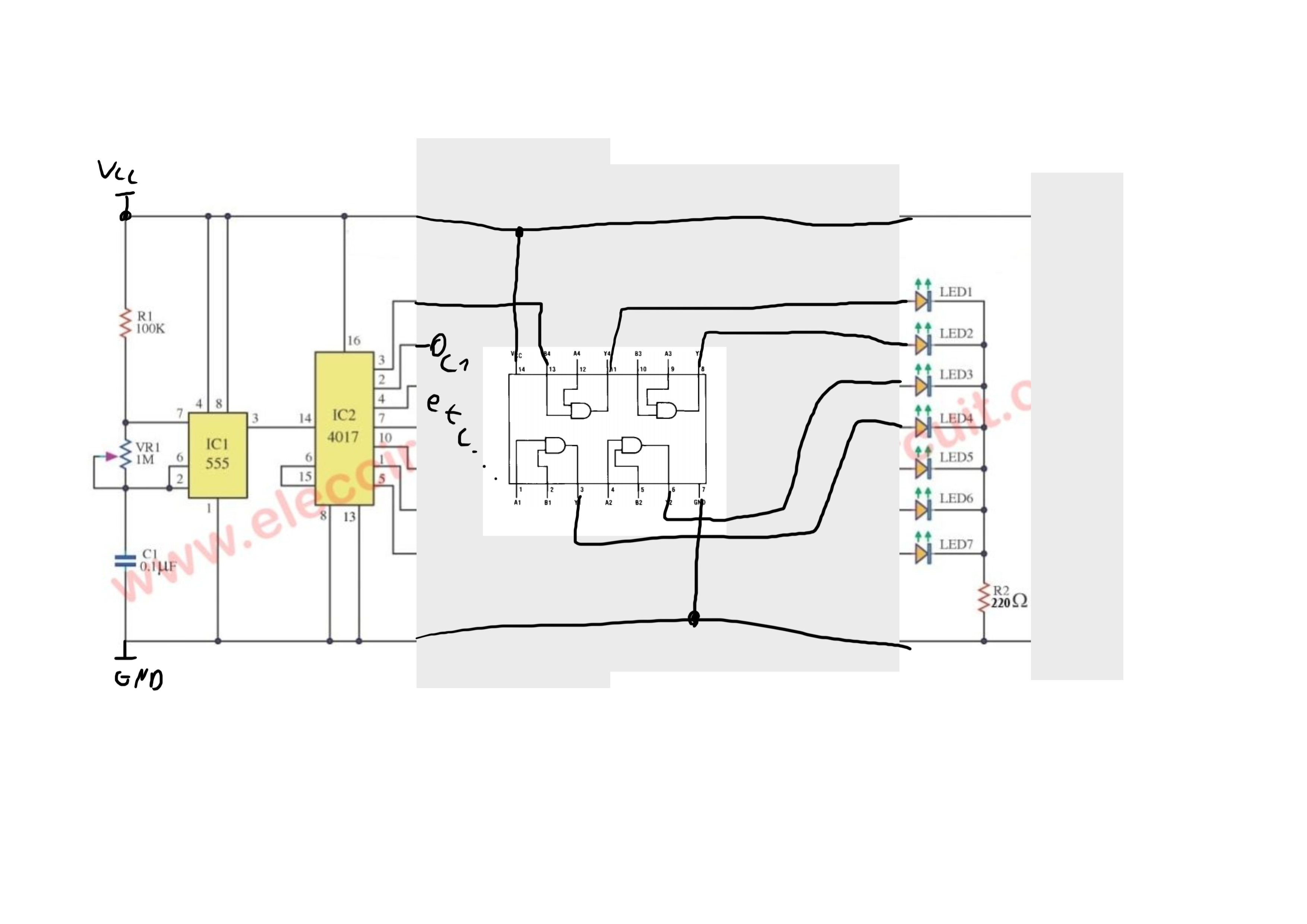
Basic Sketch
(sorry for the transparency)
If I have a cable with 4 pins, that I want to test, each pin is only allowed to be connected to the other corresponding pin.
My sketch will not work for my problem, because if pin 1 & 2 are incorrectly connected, the control LED would still light up.
Question
Can anyone give me some hints if there are designs how to separate the lines of the pins, so if any pair of pins is not connected to the correct other pin, the LED will not light up?
Try using a microcontroller (or a 555 timer with some way to cycle each wire)
have two LEDs per wire, one on the input, one on the output, such that when your wire is plugged in, the logic sends a signal down “wire 1”, LED Input 1 and LED Output 1 should both be lit. send the signal down “wire 2”, LED input 2 and LED output 2 should be lit. (etc for additional wires).
Using your error condition of pin 1& 2 being swapped, i would expect to see, when “wire 1” is enabled, LED 1 Input On, and LED 2 output On
Hint (I’m not gonna do your homework ) you need a 4017 decoder chip. It has 10 outputs, so each needs a pair of transistors to light up the led array. Another hint: these are available as chips too
Manual - Rotary switch to put one pin-pair to the LED at a time. (2x 6 pole switches cost 2ish €/$)
Automated - Get an Arduino Nano (or knock off), digitalWrite(pinX) to a pin, then digitalRead(pinX) from the expected Pin. Fancy way would be to read all pins, then serialWrite("Pin " + pinX " ok") or serialPrint("Pin " + pinX + " is connected to " + pinRead)
For a stand-alone tester, I2C to a display or light up some LEDs.
The 4017 IC is actually pretty interesting! I’ll need to look more into it and give it a thought.
The suggestion to use a manual rotary switch is great! I thought about using switches, but was turned off by the thought of having several switches, that the monkey user has to push. But rotary is (kinda) more elegant for that. I think I’ll take this one.
Using an Arduino would have been my plan B. But I hoped to find another solution, that is less complex. Because less complexity means more stability and safety if you need a brain dead solution.
On the other hand, using a display is of course pretty nice for the looks. I’ll definetily keep it on my list as future project, when I have the time to do a more fancy version.
No need for that. It just needs a push button (debounce with 100nF capacitor and a 1k resistor to the opposite potential*) to cycle through all the outputs. Each output has 2 driver transistors for a led each, one connected directly, the other via the cable. A crossed or broken wire shows up as different leds lighting up (or not in case of a broken wire) to the pair that should. If you have less then 10 wires to test, connect the next output of the counter to the reset input.
*meaning that if you have the push button and capacitor to ground, the resistor goes to +Vcc. Or the other way round if you prefer. The 4017 is positive edge triggered on the clock, see the datasheet! For a driver IC, consider the 74HC541, which has 8 drivers (i.e. 1 byte), capable of 25mA each, plenty for an LED. Note that these chips have a max power of 5V! Ideally, power from a USB charger or 3xAAA battery. Alternatively, the ULN200x series, but that’s way overkill for power requirements of a pair of LEDs. Does have a larger power margin (25-30V IIRC, well above the 4017 chip @ 15V)
In my mind, an AND-Gate with 20mA output current would be simpler. First Input gets a direct signal from the button/stepper, the second Input via the cable.
Has the added benefit of being a 20 second replacement job if socketet.
LM 317’s are cheap as dirt, would allow for 9V blocks or 12V batteries of various kinds.
The 4017 clock is too fast for the human eye to follow. So you’d need to delay it (RC network, probably). Pretty complicated calculations getting that right, especially for novices. Not impossible, but certainly more complicated then it needs to be. KIS(S)!
Certainly, but if it’s already done for you in the USB charger/battery bank…
I would see that as a benefit actually, because I can design it in a way, that the LEDs seem to be lit the hole time for the human eye. So it is easier and faster to realize which connection is defect.
If the cable is wired correctly, pressing the button will cycle through each wire and the corresponding leds will turn on. If the cable is crosswired, you’ll have an instant indication which wires need attention and a broken wire will show up as one led lighting up. Mount leds D1-D4 in a single column, then mount leds D5-D8 in a column parallel to the first, so leds will correspond as D1&D5, D2&D6, etc. Resistor R1 is 1k, the others 560 Ohms. Capacitor C1 is 100nF, power is a USB charger or battery bank.
I don’t quite understand the functionality of 74HCT541 yet. It is a buffer as far the datasheet is saying. But I’m not sure, what that really means.
Do I get it right, that G1 & G2 are always on, because they are active LOW. So any HIGH signal on the inputs (A0…A7) will correspond to a HIGH signal on the outputs (Y0…Y7).
As the 4017 cycles through the inputs, the cable pins will light up accordingly to their connection while pins 5…8 will always light up.
Yes, the 541 driver is just to “amplify” the signals from the 4017. If you can find a 7400 series equivalent of the 4017 (good luck on that ), that chip would be able to drive the leds directly as the TTL inside that series is designed to handle larger currents then the CMOS 4000 series.
In a way, I’m “abusing” the 541 chip here. It’s usual role is to buffer data between chips on a data bus (hence the octal design, 8 bits=1byte). When either G1 or G2 is logic high, the outputs are in ‘tri-state’, meaning they’ve basically been disconnected from the internal circuitry. So any data traffic over the bus will not be seen by whatever circuits are on the input side of the 541 chip, thus preventing data corruption due to shorts. This isn’t the place (nor time!) for an essay about (early) digital technologies, suffices to say these chips were still current when I studied electronics
I gave it some more thought and while I like the variant with the 555 timer to make it fully autonomous, I also like the variant with the pushbutton. I just realized that the pushbutton is the timer in your scenario, @Dutch_Master. So any time the button is pressed, the next LED will light up. That’s pretty simple and neat, I think.
I will experiment with both layouts, as soon as I get the ICs delivered.
Thank you very much for the great help!
I already learned a lot from this thread
Could maybe just a simple ethernet (RJ-45) tester work? The ones I have used will cycle through each lead with a led flashing showing that there is connection from the sender unit to the reciver unit. So just make a pair of custom RJ-45 cables with color coded aligator clips or whatever is most convenient for your use. https://images-na.ssl-images-amazon.com/images/I/61L8wjwr22L._AC_SX522_.jpg
In theory, yes. In practice it’s a bit more complicated A simple ethernet cable tester will cost you at least $20 (US!), whereas the diagram I’ve made will set you back a grand total of 2-3 bucks. Admittedly w/o a housing, custom PCB, sockets, manual and product packaging, but cheap nonetheless.
I would also like to add, that it’s more fun to do it myself and learn a lot by it. Also I don’t need to modify the Ethernet tester.
As far as I’m aware, Ethernet has crossed pairs or something (or was it mirrored?). So I’d have to modify it nonetheless, because my cables have different connection types.

 ) you need a 4017 decoder chip. It has 10 outputs, so each needs a pair of transistors to light up the led array. Another hint: these are available as chips too