Quick note for later readers: if you need more wires checking, add a 2nd 541 chip with corresponding leds and resistors, wired the same way as the one in the diagram above to outputs 5 to 8 on the 4017 chip. The reset input is then connected to the 9 output. This gives you up to 8 wires in a cable. If you need more then 8 wires testing in a cable, consider a commercially available cable tester, as outlined above, although there are ways, more complex then this diagram provides for, to build a DIY solution w/o resorting to programmable logic like microcontrollers or FPGAs. (hint: CMOS 4514+2x4027)
depending on what type of cables you are testing a typical network tester works fine.
so will using a good multi-meter or continuity tester. But you need to have a thorough understanding of the cables construction.
learning electronics and how the components work
a good way is to build the qrp ham radio kits from qrp labs and 4 state qrp.
the kits are low cost, and the instructions are easy and explain how the components work together.
for example I am an Ozark Patrol kitter,
Its a regenerative shortwave radio receiver you build from a kit.
http://www.4sqrp.com/ozarkpatrol.php
but they also have a lot of other kits as well.
BE WARNED you are entering in the realm of ham radio!
you need to get your tech, or general license to transmit on any transceiver
but you dont need a license to build or listen to them.
4 leds, 4 switches, 1 resistor.
all leds are on power bus, they only need a path to ground to complete the circuit.
should detect crossover and bridged pins.
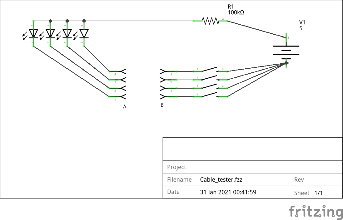
could swap your 5v power for a 3.3v cmos battery (cr2032) and probably skip the resistor.
1 Like
@Gnuuser As interesting as radio is, it’s quite a step upward of a simple cable tester, which was the subject here. And as I explained earlier, buying a commercial cable tester cost much more then some logic circuits and other components, as well as having pretty much zero teaching value.
@d0rk That circuit isn’t gonna work. The resistor value is way to high (100k) and should be 560R instead, at most. As for the 3V3 option, you’d still need a resistor, red and green LEDs have a 1.5-1.8V voltage drop, so connecting that 3.3V will blow the led’s immediately. Some 100-120 Ohms suffices in that case.
1 Like
the simplest cable tester is simply a continuity tester but your checking 1 conductor at a time.
if you are building a network cable you can pick up some cheap testers that work quite good.
https://www.ebay.com/sch/i.html?_from=R40&_trksid=p2380057.m570.l1311&_nkw=network+cable+tester&_sacat=0
I used them when designing control cables for automation machines. it was simpler to just build the adapter cords to plug into the network cable tester.
trying to design a logic probe type multi led tester is merely complicating things beyond necessity
the reasoning behind mentioning the rad kits was not promoting them but the fact they teach you what the components do
1 Like