Hi,
after seeing @wendell s video of the NZXT Hue + i finally got myself to take pictures of my already scratched and opened lighting controller.
Join me on this tour!
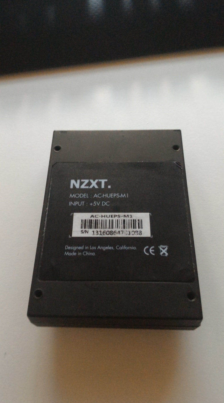
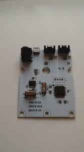
Info is above each picture. Speaking of info, this is the proof that this is a hue +.
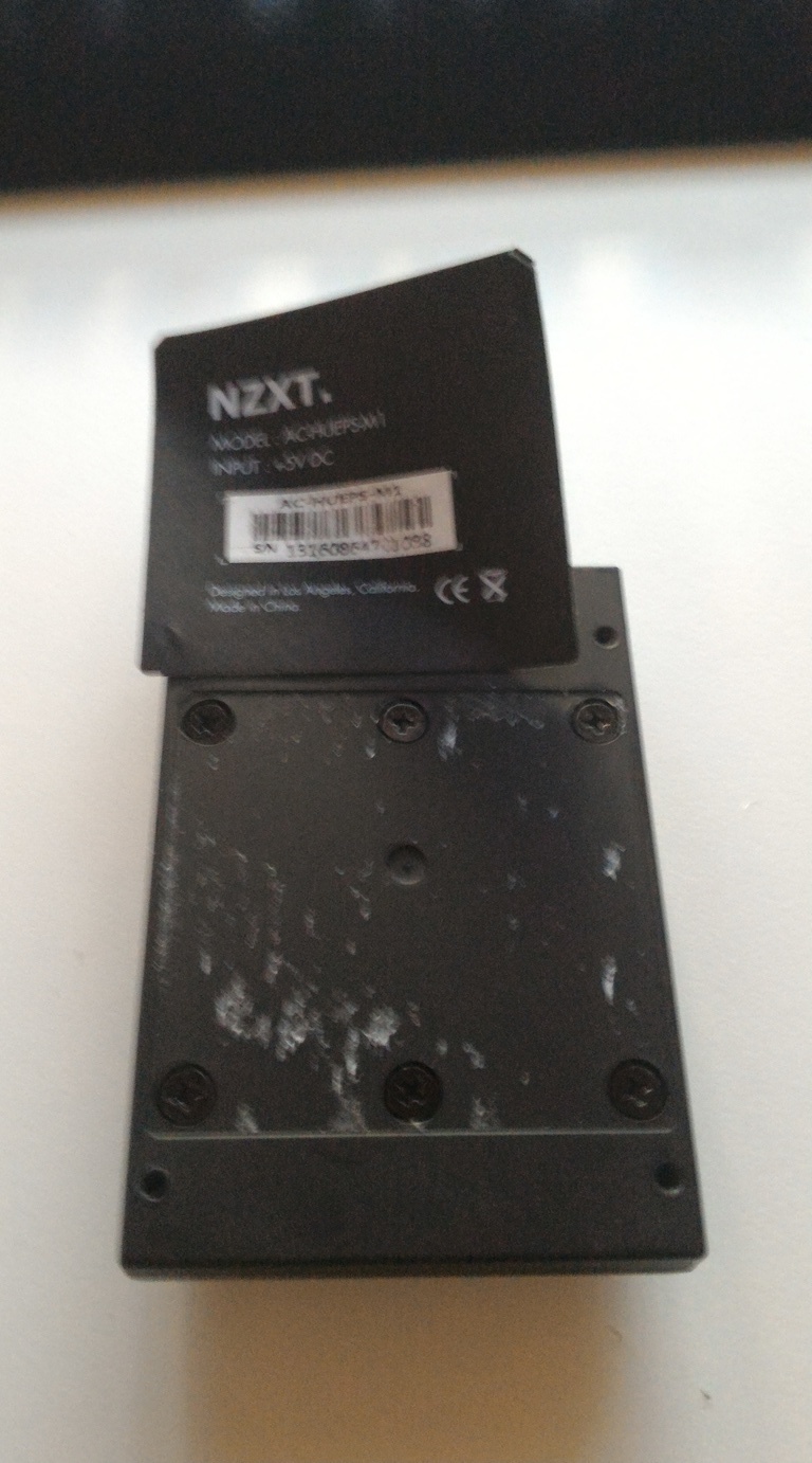
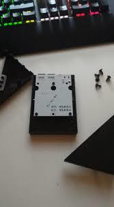
The screws are under the sticker. Stupid me who scratched up the hole outside with screwdrivers before thinking.
Now i won’t ever be able to sell this piece of crap!
Look onto the PCB with 3 white LEDs. Still don’t know why they haven’t made them RGB!
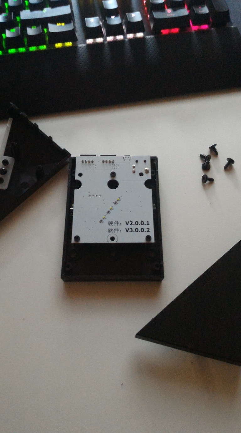
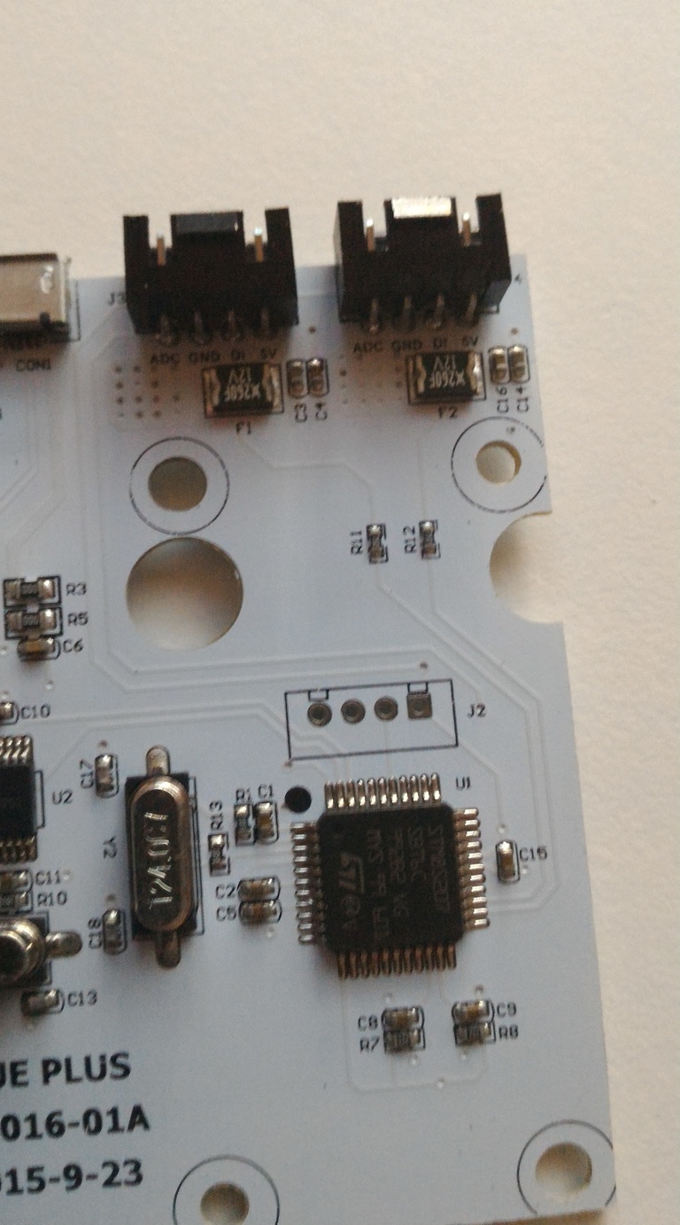
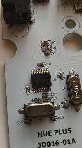
the PCB from below, where everything is located.
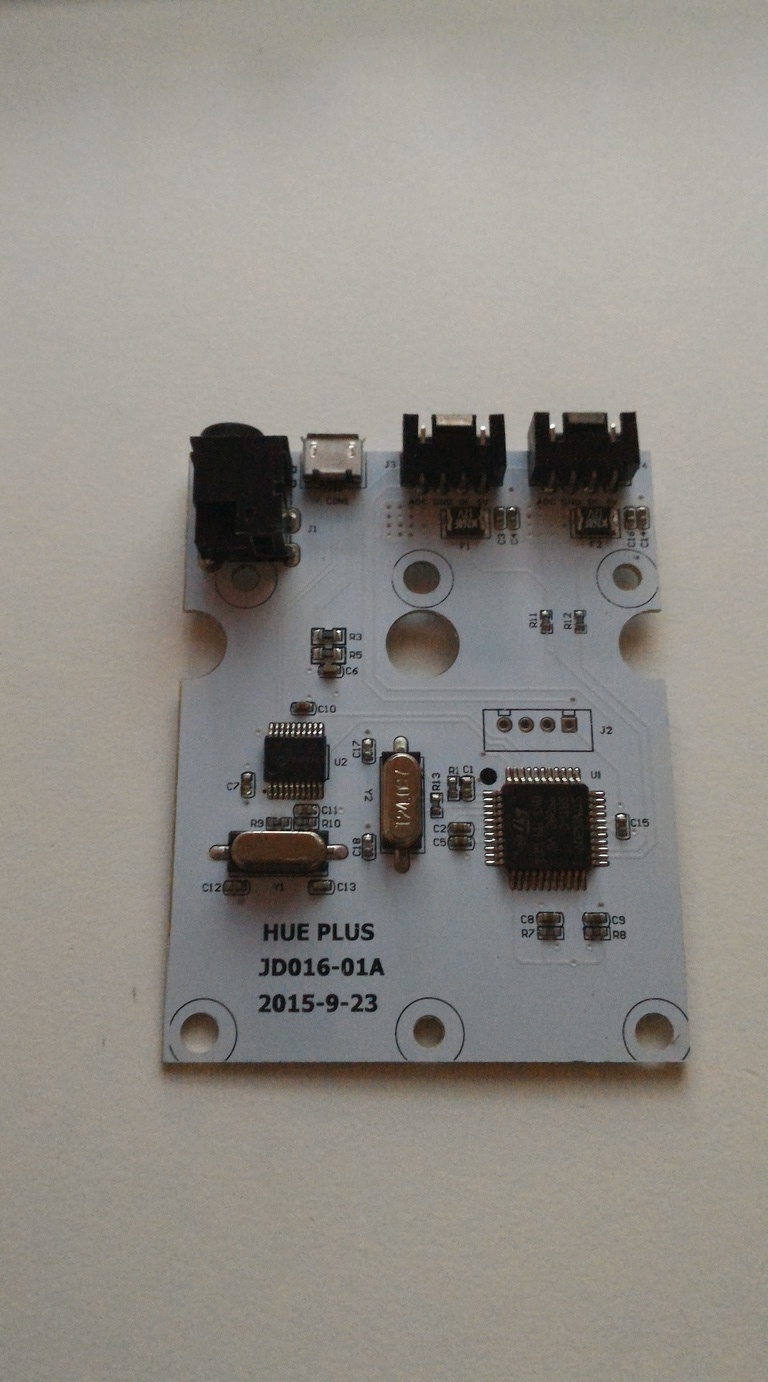
a closer look at the main controller.
STM8S207 8bit MC.
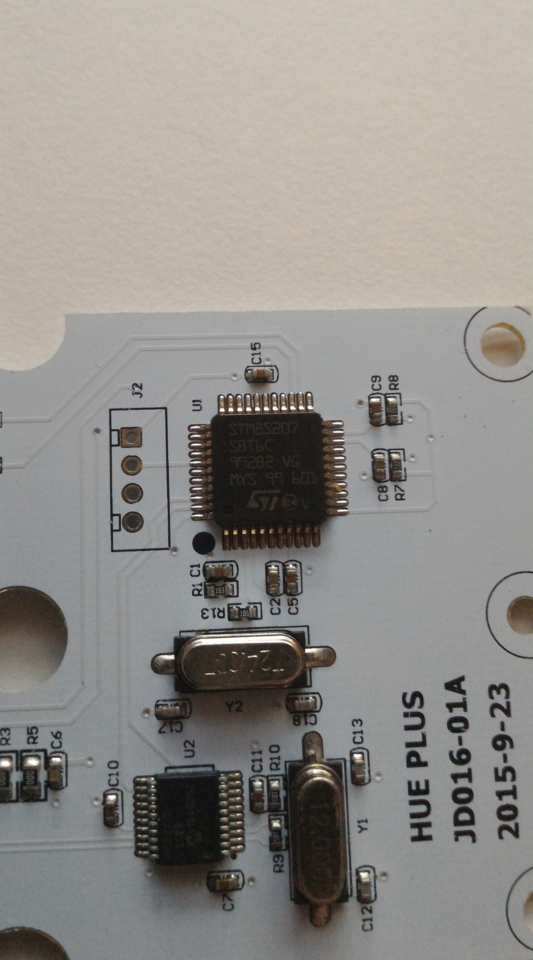
The USB part an MCP2200 USB Bridge

A closer look at the traces here
The LEDs used are WS2812b individualy controlable RGB LEDs.
They need around 5V and a precise timed signal to be controlled.
To get the timing right, you need to know how many of those LEDs you have.
That’s why each channel consists of 4 pins.
Controler:        LEDS:         Description
5V                   5V
DI                    In  / Out       The Signal
GND                 GND
ADC                 FD                10 Ohm Resistor from between FD/ADC and Ground.
The controller detects the amount of LEDstrips through a simple voltage-divider.
4 strips = 40 LEDS have 2.5 Ohms of resistance.
That means, that you can easily get different WS2812 (b) LEDstrips and that you can use them with this controller if you only use 40 LEDS per channel and if you solder a specific amount of resistance between GND and ADC.
2.5Ohms for 40 LEDs.
Note1: Even when you put more then 40 LEDs onto one channel, only 40 will light up.
Note2, if one channel stopped working, its probably just the big fuse below the connectors.
That was basically everything in terms of hardware EXCEPT the USB Bridge.
USB Bridge is for a different time.
Overall this is a nice design, pretty cheap parts.
Why have i paid 60 for that ?
Why is it so fuc**n huge ?
And why does the software not run on linux ?
NZXT ?


 he is OK now.