This thread is meant as a hub to share projects related to electronics and microcontrollers, talk about tools and parts, taking a look into things, troubleshooting circuitry and so on.
A few things to note:
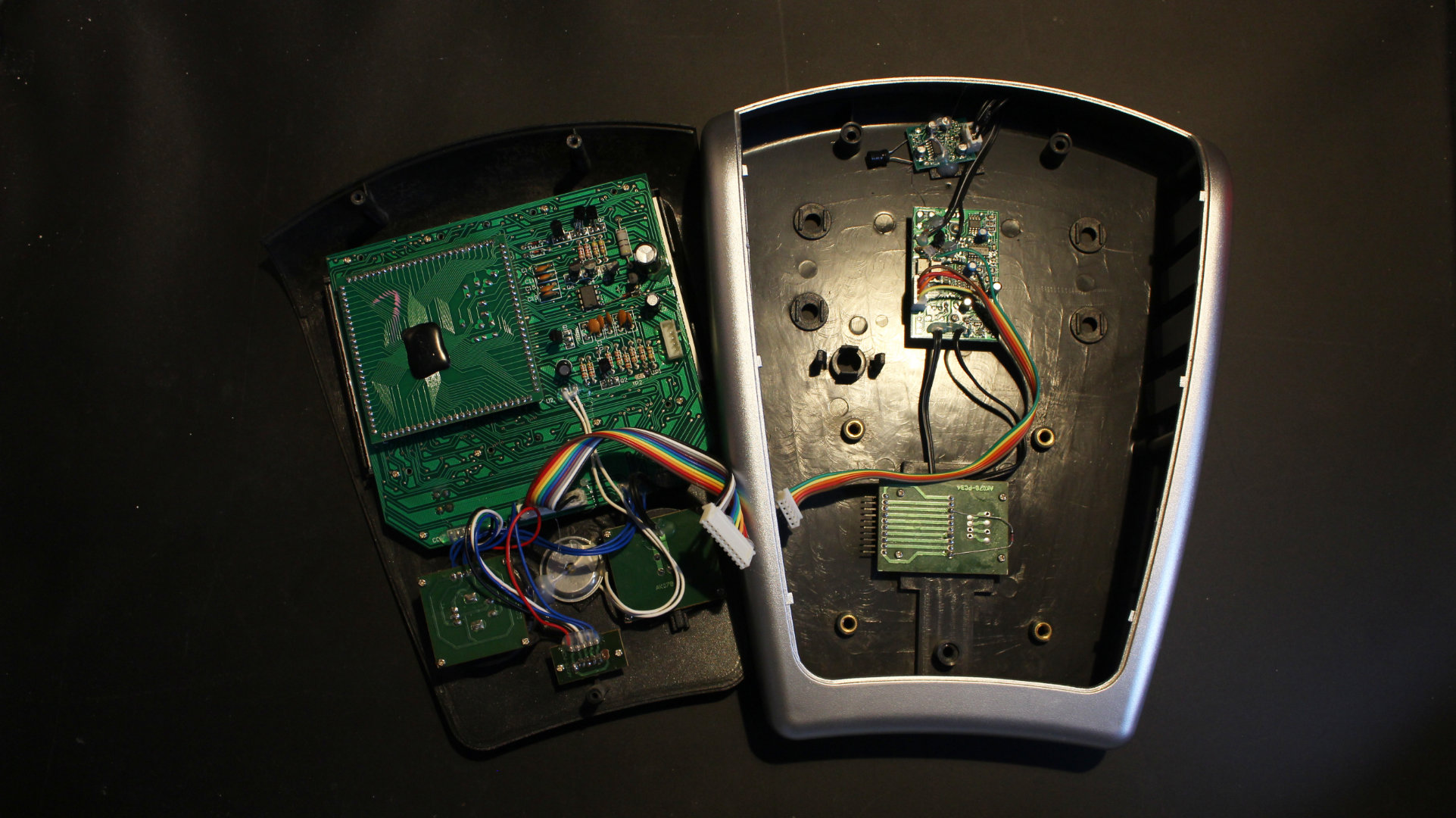
Plugs everywhere! The whole thing basically is plugged together! No idea why anyone would do that, no consumer would ever take a look in here or service anything. Note that all components are through-hole making them easier to solder by hand.
And all the chips are name brand, all TI (texas instruments) or IR (international rectifier).
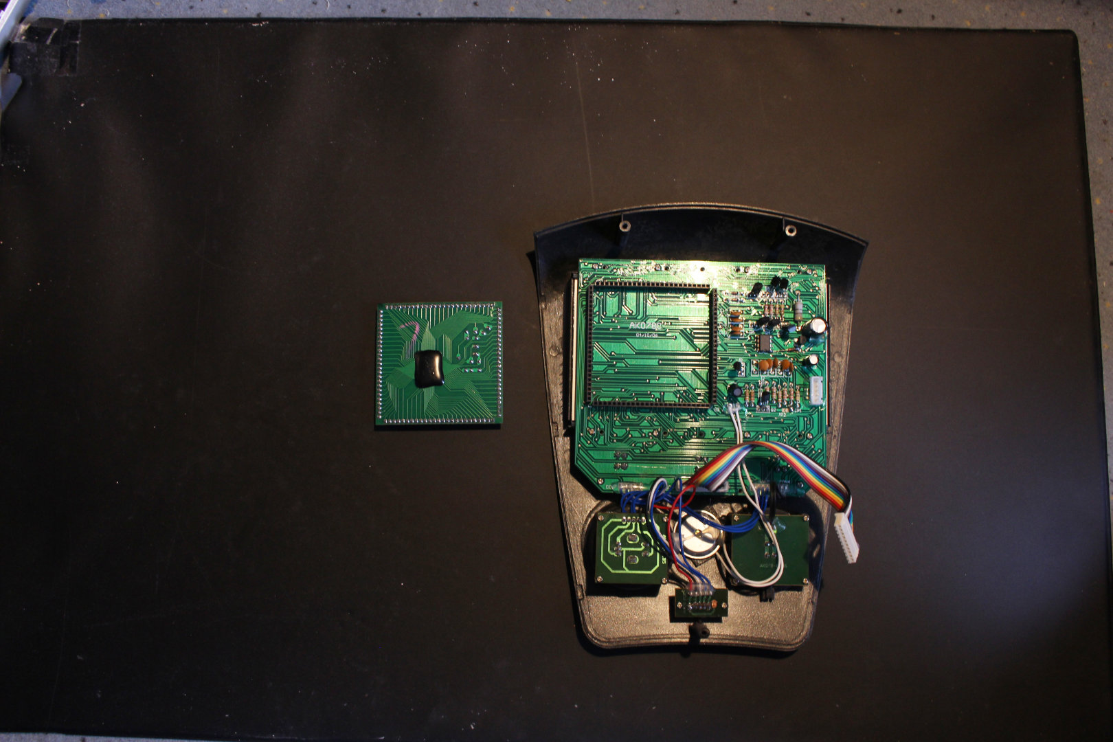
The black blob covers a microcontroller on the PCB making it cheap and easy to connect to the board. However someone seems to have been desperate and put it in a socket of sorts. So there are 4 bars of pins serving as a “cpu socket”.
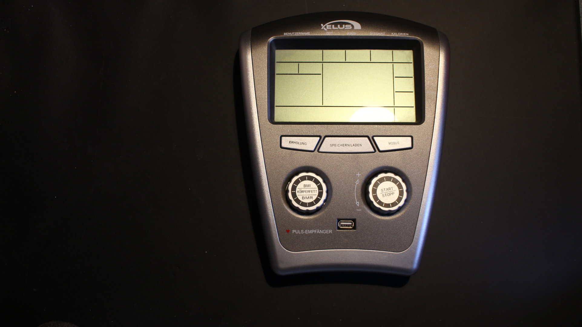
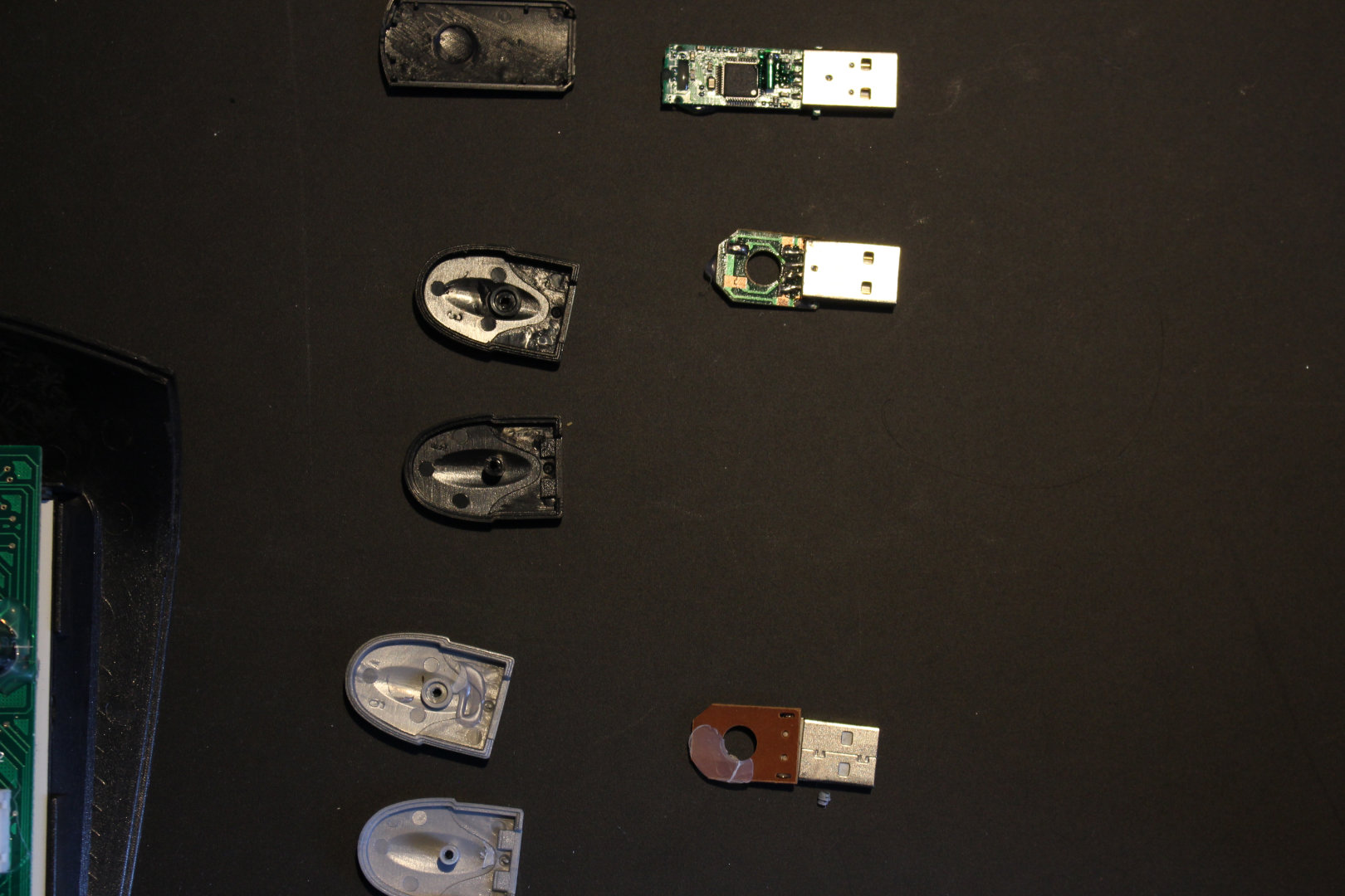
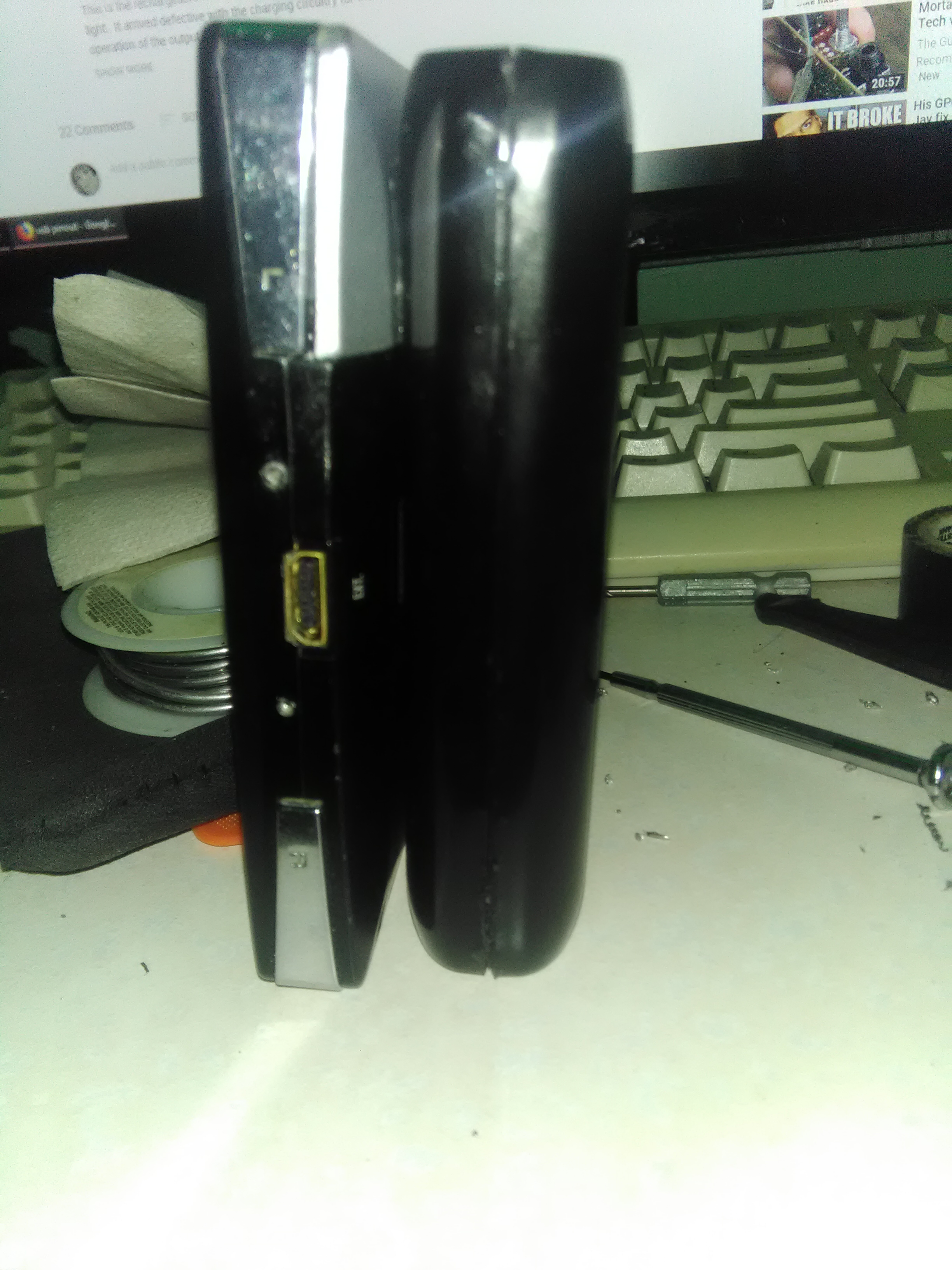
Remember the USB connector? It is physically a USB connector, electrically, it is not.
Took a look into the “USB”-dongles…
The top one is a real USB stick. The two below that are NOT! The 4 lines in there end in solder pads. In the one I turned over, GND and +5V (the two outer pins in USB2.0 connectores) are connected together. Plugging that into any computer will probably render that USB port unuseable.
Here is a close up shot. I marked the two rails. The lower most soldering pad is barely connected (checked by probing it). Would probably allow for 3 A or more to flow.
Booty:
I got about 3m of “rainbow cable” wich I will put connectors on and use in some project:
2x 3.5mm "mono audio jacks"
And a bunch of wires plus some things from the controller.
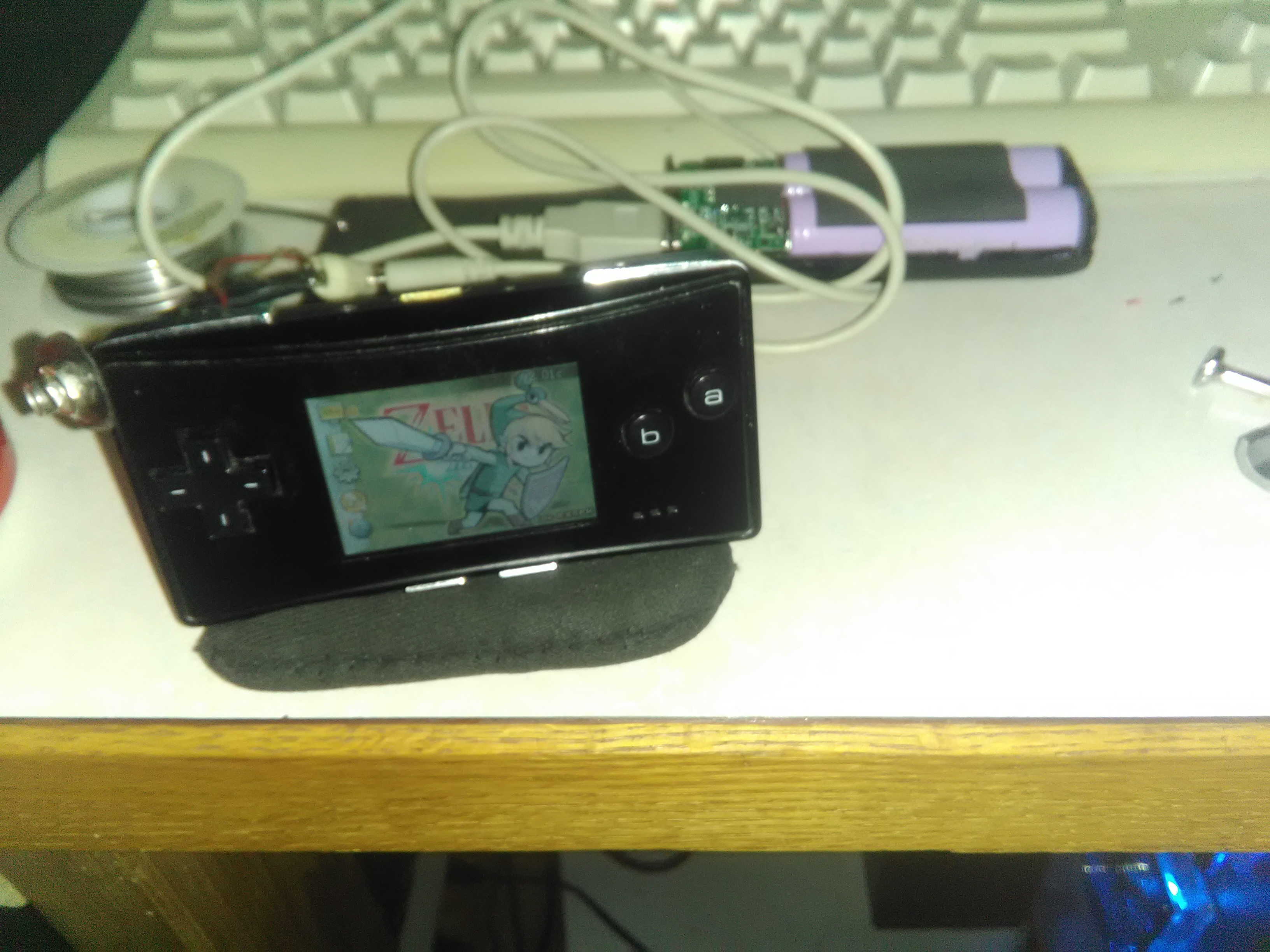
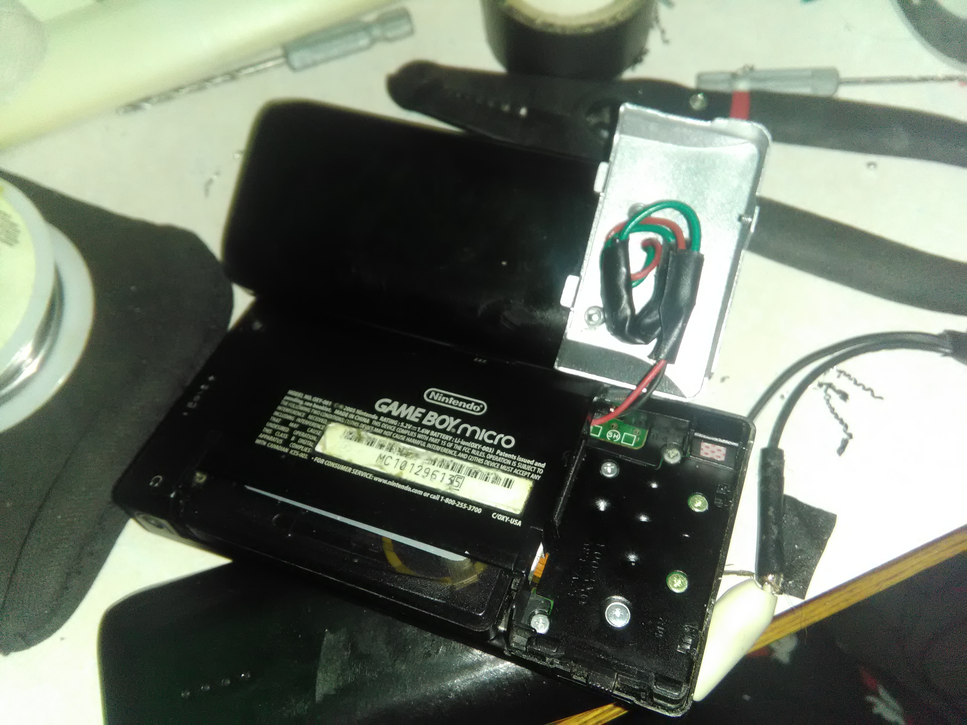
attached a 6700 mah battery bank, to the back of my gameboy micro soldered onto the back of the usb port(no pics off that part cause didnt wanna mess with the wires much since didnt have any hotglue/silicone to hold them onto the port and is no physical conection other than the little bit of solder
circuit is just 2 diodes in series, to get the desired voltage drop(since it worked out perfectly) to be 5v with 2 silicon diodes being ~0.7v forward voltage leaving ~3.6 across the gameboy, which has a normal lithium cell which nintendo states at 3.8v
and as long as dont go open circuit or go over 2amps(which is also the max power the bank outputs) voltage should be pretty stable, didnt use resistor because no idea what the actual power draw over time is, or have a modern scope to be able to get a graph to show me, so if the current draw varies so would the voltage, but being a arm computer designed to be mobil assuming has some sort of power saving features, and with the sleep mode and stuff, the power draw could vary enough that could have a bad time with a resistor,
and the current draw is so low(for average) that cant really use a regulator although i did have a little ti one i could use, but efficiency would be terrible like 70~80% at best
didnt touch the data pins so it can still sense when plug a phone in what charge rate to do and such
Would anybody know any good books that cover the fundamentals as least. I would like to get at least get a overhead explanation on the development flow and the terminology?
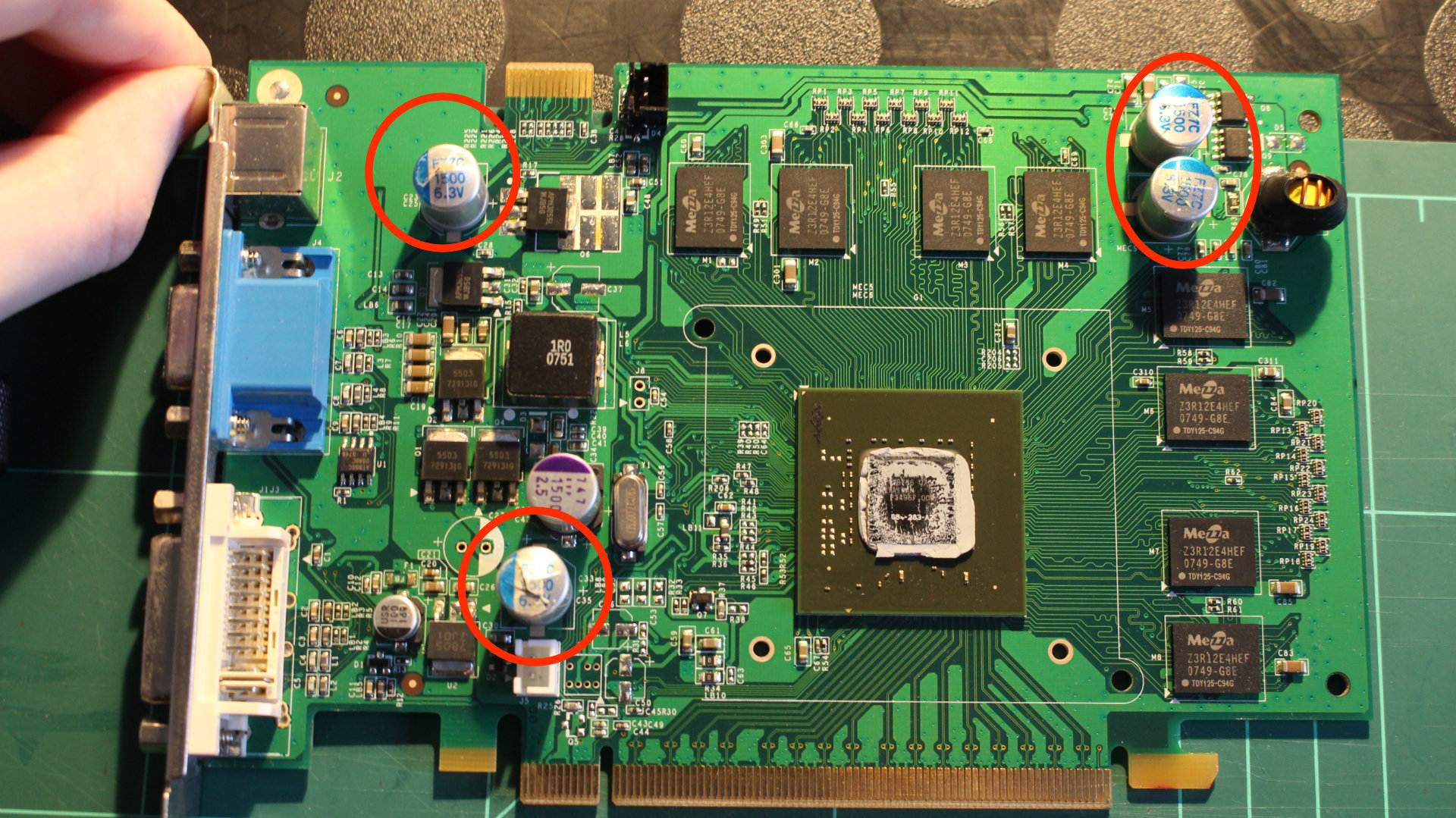
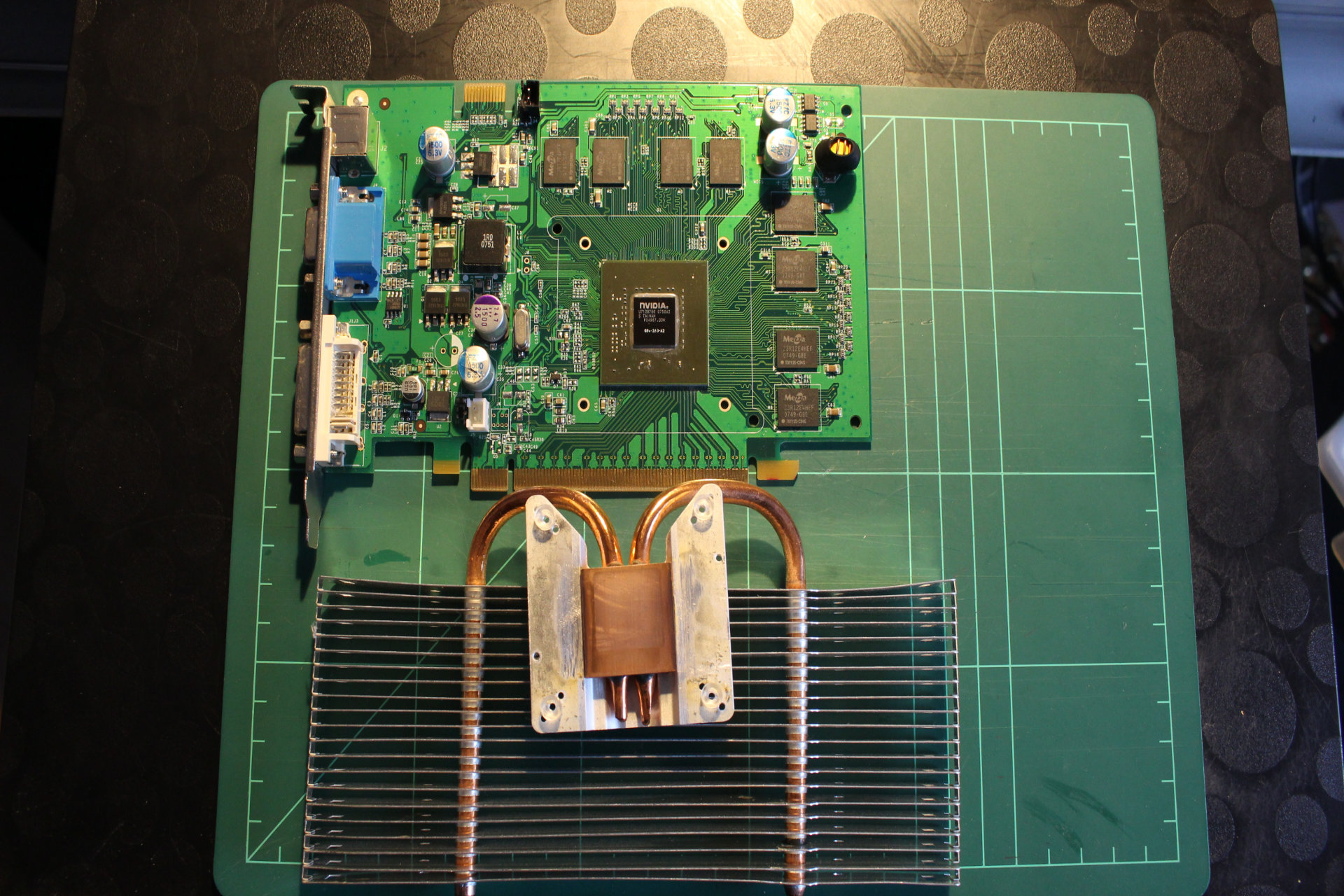
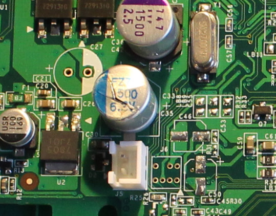
I will replace the the 4 dead capacitors and the one still “intact” one with Panasonic VF 1500/6,3C-G ones. Either that revives it or I wasted 4.23€ on capacitors.
There are weaknesses built into the casings of the capacitors so they fail in a controlled manner. And those blew on four of them. You can see the electrolyte spilling on them.
No idea if it is just the capacitors beeing shorted or if there is damage to the core itself.
I read something about how in the embedded engineering process the first step is the engineers will order a kit that can be solderd together. Is there a way to make a design and ship off an order for its manufacture or how does that work?