Inducing ECC Errors - hardware way

The goal here is to document my attempts and results to inject ECC errors for the purpose of verification whether error correction is functioning.

This is especially relevant on Ryzen where some boards seem to advertise being able to take ECC UDIMMS but don’t specify if ECC will be functional.
The situation is further complicated by AMD essentially mandating that Desktop Ryzen boards cannot declare full ECC validated support - most likely for the purpose of market segmentation.


The solution I am attempting here is by no means anything new:

Initial inspiration

Later reproduced by diversity on ixsystems/truenas forum:

Corraborated by @Mastakilla:

And thanks to @kwinz for bringing to my attention a similar approach taken by Passmark:

Their tool is was confirmed to be delayed ATM due to silicon shortage:

I fully expect this to be the tool to use in the future but at the same time I wouldn’t expect it to be as cheep as an aliexpress DDR4 riser, a button and a few wires.


So the main thing to use is this kind of aliexpress DDR4 riser (~6$):

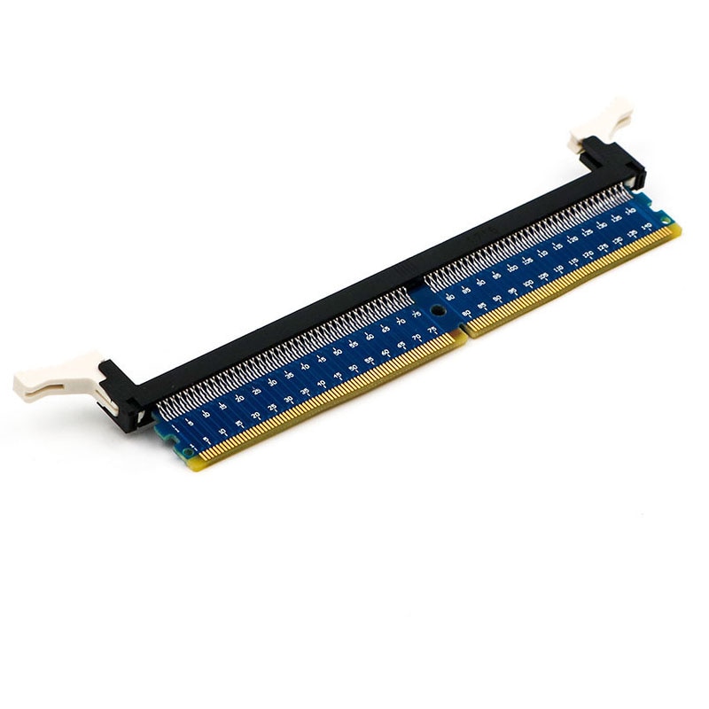
Apart from that it’s only wires, a mono-stable switch (reset type) and maybe a resistor.

As mentioned in the first paper only a few wires are really necessary but using a riser makes this into a more easily reusable tool that could be included into mobo testing (wink, wink, @wendell)

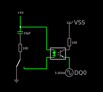
The idea is basic: short a data pin to ground - this causes an error and if ECC is functioning then we should get a report (* PFEH may stir things up - more details will follow)

Depending on the module type there are various documents that can tell you which pin is which:

Vss designates ground
DQx designates data pin

First 16 pins for faster reference:

Pin Function
1 Not conencted
2 VSS
3 DQ4
4 VSS
5 DQ0
6 VSS
7 Data Mask
8 Not conencted
9 VSS
10 DQ6
11 VSS
12 DQ2
13 VSS
14 DQ12
15 VSS
16 DQ8

I tried a few different data pins but none seem to behave different.
So my pin selection was simply based on convenience of running short wires.
(But I would advice against using pins beyond 144 - since not all DIMMs are dual sided.)


Software used:

Errors are best observed in memtest86+ - they appear reliably.
One note: after shorting the pins there will most likely be multiple errors - some appear immediately but some can appear a while later. (If a write is corrupted then memtest can potentially read and verify it after going through whole memory space first)

Linux kernel reporting was flaky - it worked but for some reason I am routinely unable to trigger errors more than once. Not sure why - This is something to look at separately


Hardware used:

X470D4U (3.50 BIOS)
Ryzen 2600
Kingston KSM26ED8/16ME


Observations:

How BIOS settings change things when a 1-bit error is introduced:

PFEH disabled/auto PFEH enabled
ECC enabled/auto 1bit corrected error report zero errors/reports, acts as if nothing happened
ECC disabled 1bit uncorrected error 1bit uncorrected error

The matter of resistors: shorting to ground has a potential to induce current that could damage something. So shorting through a resistor seems like a good idea but even without it I am yet to fry anything.

Results of shorting DQ0 to VSS through various resistors:

riser variant resistor ECC enabled ECC disabled
third/soldered 100k no error no error
third/soldered 1k no error no error
third/soldered 220 no error no error
third/soldered 147 no error no error
third/soldered 122 no error no error
third/soldered 100 1bit error corrected reboot
third/soldered 47 1bit error corrected reboot
third/soldered 10 1bit error corrected reboot
third/soldered 0/short 1bit error corrected reboot

Those resistor tests were done using third riser iteration with a button. (described below).
PFEH setting in the BIOS was set to disabled.


When trying to cause 1-bit errors by shorting VCC to data pin while ECC is disabled I am failing miserably. I assume that this is because hand-shorting is too slow.

However - just by touching an exposed data pin with a piece of wire without shorting to VSS I can get one of uncorrected errors:

riser variant resistor ECC enabled ECC disabled
first/second N/A - any resistor/piece of wire works randomly 1bit error corrected report 1bit uncorrected - real data corruption

This is most likely a result of small static discharge that is short enough to cause only a singe error instead of a continuous stream while shorting.

Described “static discharge” approach is a pain but it is reproducible and used to test configurations with ECC disabled.


Riser iterations:

My first attempt was mentioned here:

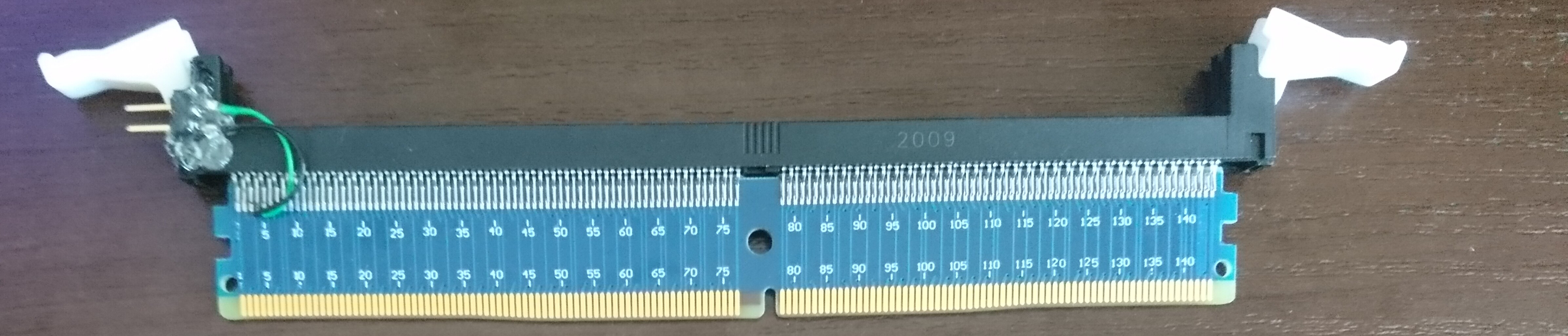
I added goldpin connectors to pin 4 (ground) and pin 5 (DQ0).

First think I noticed was that I cannot use long wires on Data pins - the board would not post. Most likely data integrity is getting decimated. This makes things less convenient.
But I can use long wires for ground if I need to.


Second iteration: Checked different pins, shorting 2 data pins - still flaky and frustrating

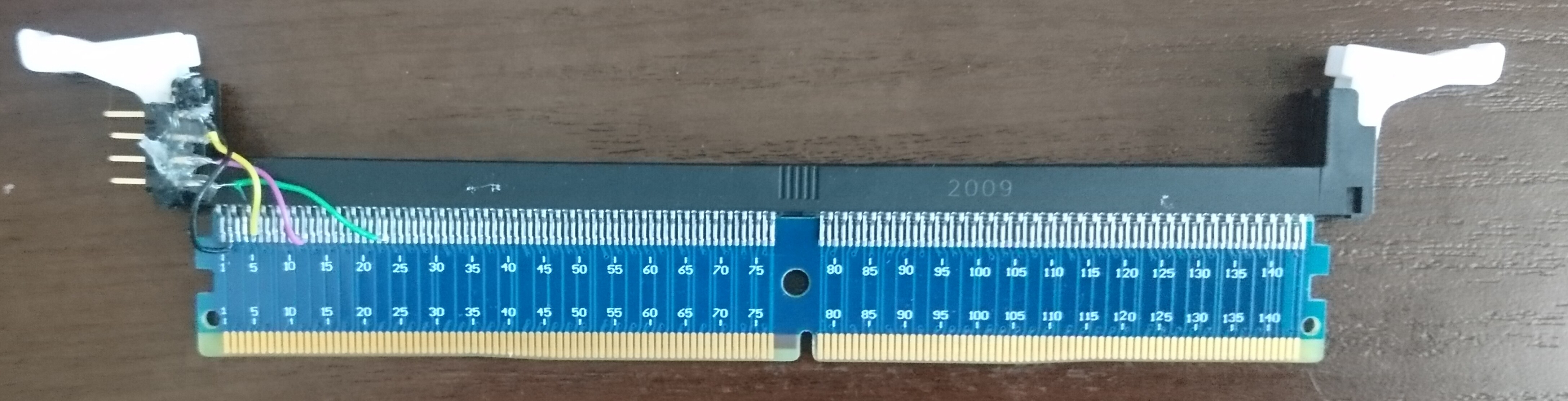
Same as the first one but with 2 more wires going to different data pins.

I was hoping to get some 2 bit errors by shorting 2 data pins together but it’s not really going well. I either see 1 bit errors or instant reboots. Most likely It’s just that my fat fingers are too slow and multi-bit error signal handlers get broken as well. Probably the best thing would be to make a simple circuit doing very short pulses.


Third Iteration: back to 2 pins but much more reliable with a switch


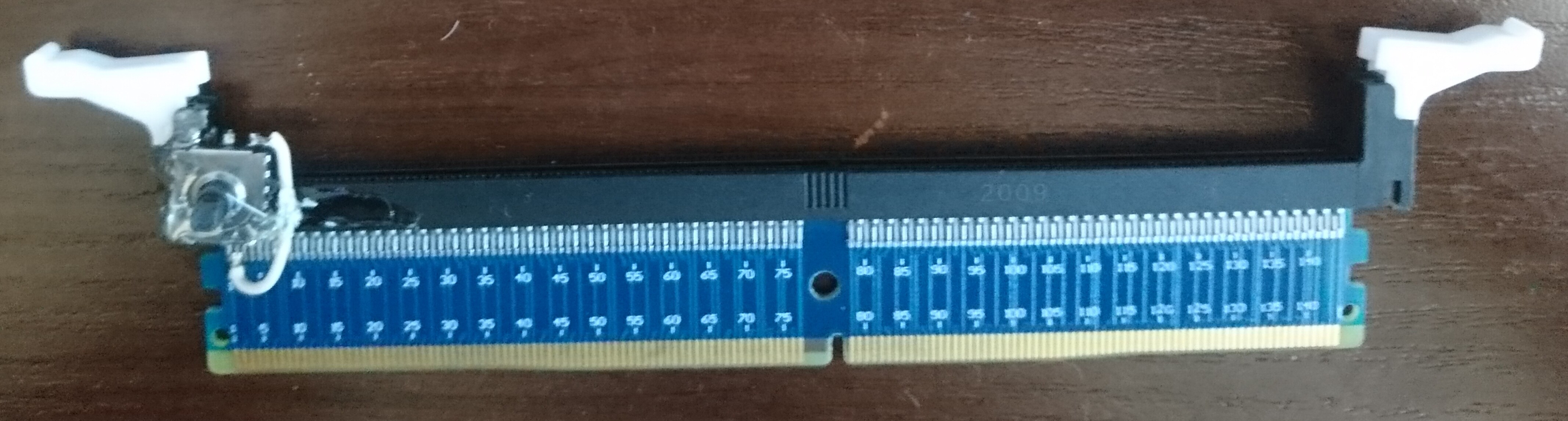
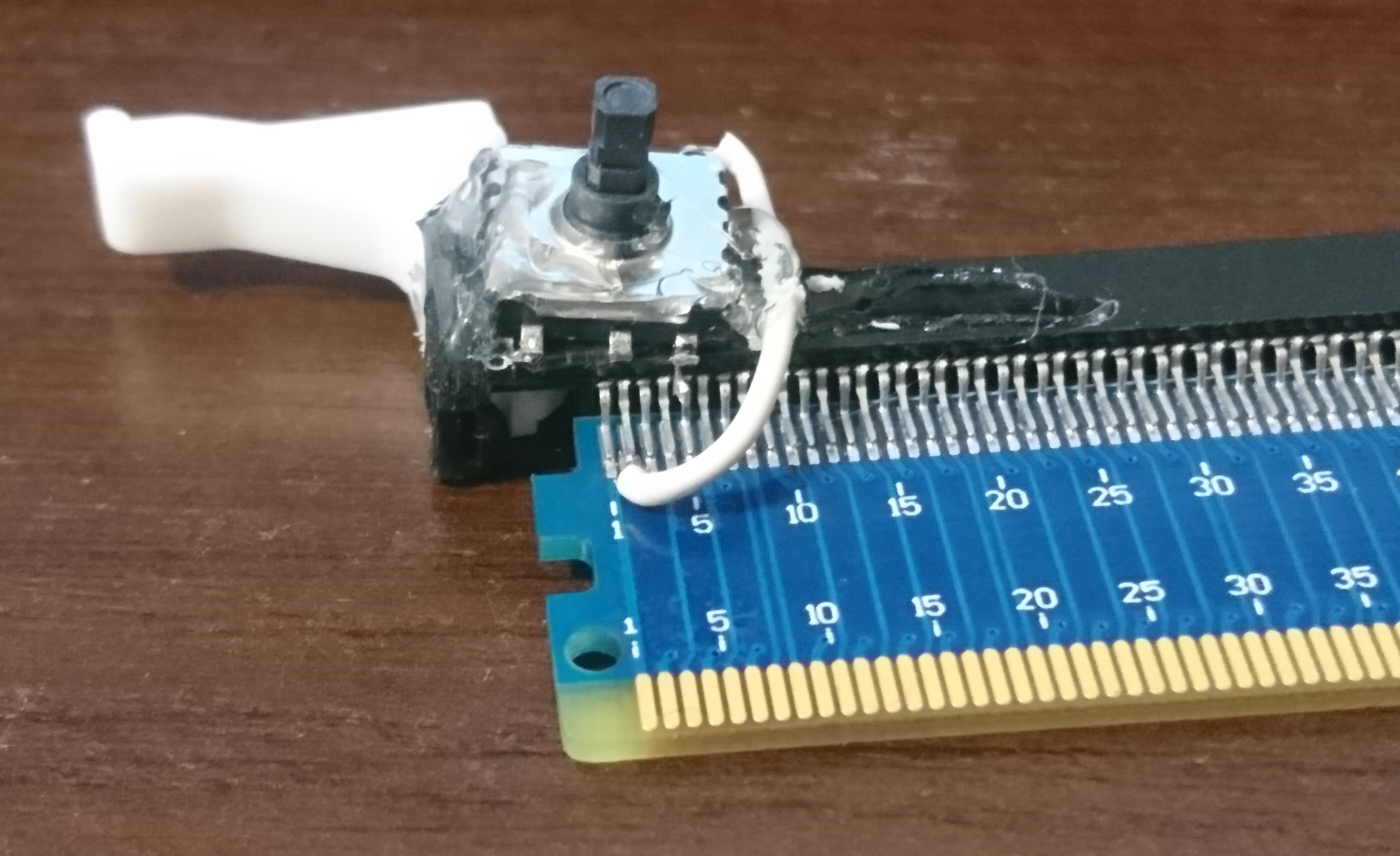
I had a joystick like-switch laying around so I used it and the reliability and ease of use is night and day. Hot glue isn’t super secure now I don’t have to fiddle with shorting wires.

This version is good IMO enough to check if 1-bit errors are reported correctly. It’s very easy to use but I will need something better for 2-bit errors.

It is causing instant reboots/freezes when used with ECC disabled - most likely because my fingers are not fast enough and it causes thousands of errors under the hood disturbing not only random data, but also control-flow.


Misc notes:

  • A board sometimes fails to post. Most frequenly the reason was too long data pin soldered wires. But sometimes it was simply bad memory seat. Just pushing it a bit harder or reaseating would fix it.
    The post codes while this happens are kind funny: “DE” “ED” “DF”, but when watching them going fast I always interpret it as “dead af”
5 Likes

Couldn’t you flip a bit with enough magnetic waves going thru a room?

You could flip a bit with a piece of uranium or by poking pins with a needle while running as well. The goal here is something that is cheap, reliably reproducible and easy to use.

Buy some uranium dust then. Theres availability lomewhere, ppl on yt were freaking out that you could buy DU133 On amazon like 3 years ago.

Later on design a pcie card with a little radio active pulser on it. Could be done cheap, and ppl’d need to verify if intel was lying on the new sheet or not so you’d make bux

I wonder how possible it is to MITM a DIMM by modifying one of those risers. Probably not injecting data, maybe not realtime, but a dumper would be kind of neat. Full-RAM encryption is a thing but I don’t know how mainstream it is.

You just gave me an idea.

Hey op whta if you got somethitg like a mac pro where you put the ram on a board and plug in the board? I bet you could manipulate all sortsa stuff that way. Theres bound to be something with ddr4 mih that sorta tooling somewhere

MITM injection cards exist:

https://arxiv.org/pdf/2003.04498.pdf (page 10)

Not really for dumping memory but related and
dumping memory is probably much easier achieved with freezing (Cold boot attack).
example: Cold-Boot attack for reverse-engineering the Error Correcting Code (ECC) - YouTube

+With much more prevalent builtin transparent memory encryption these days it’s not really something that would be very useful.

2 Likes

Seems like a “pick 2”-situation.

Your switch idea may be the right idea. Put a fast MOSFET in place of the switch and create some way to produce as sharp of a pulse as you can to drive the MOSFET.

Alternate route: Horse-shoe electro magnet, function generator and power amp.

1 Like

Why not use the easy way to accomplish this?

Boot up into Linux.

dmidecode -t memory | grep ECC

It will show if ECC is functional there.

Non-functional:

fk@Microscope-L:~$ sudo dmidecode -t memory | grep ECC
fk@Microscope-L:~$

Functional:

[root@backup archive2]# dmidecode -t memory | grep ECC
Error Correction Type: Multi-bit ECC

If you want to play with this to see if ECC is working, have fun. If you just want to know if it works, do it the lazy way…

3 Likes

Updated the first post. Will add how BIOS options impact things next.


Not really, the third iteration with a switch is already “ok” in all 3 aspects. It’s sub 10$, I can get 1-bit error every time and to use I just put the DIMM into a riser and that riser into the mobo slot - that’s it - push the button for errors.

But are other bad aspects of this approach:

  • Robustness - hot glue, protruding wires and weak solder joints make this fragile
  • It requires some dedication and soldering.
  • Low but non-zero chances of damaging components. (Power pins are fortunately not that common and generally grouped together)
  • Fingers are fat and slow - As you said MOSFET would be much better and would probably allow for 2 bit errors that don’t cause instant resets. I was also thinking about using and optocoupler instead to not rely on common ground but that’s for something further down the line. (Not entirely sure if using dimm power pins or external power is better yet)

Yes, it will work, but this does not answer every question.
If mobo is secretly enabling PFEH then yes, ECC can be functional, being visible in dmidecode but even if errors occur they won’t be reported to the OS.
And if there is no BIOS option to disable PFEH it then you can only guess if you are experiencing “stability” or “instability hidden by the PFEH”.

Also a pedantic side-note about the “dmidecode -t memory | grep ECC” command (sorry): This will show multiple entries - for both physical memory and cpu cache. You want to check if ECC is declared in Physical memory section.

For example:

Handle 0x0013, DMI type 16, 23 bytes
Physical Memory Array
	Location: System Board Or Motherboard
	Use: System Memory
	Error Correction Type: None
	Maximum Capacity: 128 GB
	Error Information Handle: 0x0012
	Number Of Devices: 4

...

Handle 0x0015, DMI type 7, 27 bytes
Cache Information
	Socket Designation: L1 - Cache
	Configuration: Enabled, Not Socketed, Level 1
	Operational Mode: Write Back
	Location: Internal
	Installed Size: 576 kB
	Maximum Size: 576 kB
	Supported SRAM Types:
		Pipeline Burst
	Installed SRAM Type: Pipeline Burst
	Speed: 1 ns
	Error Correction Type: Multi-bit ECC
	System Type: Unified
	Associativity: 8-way Set-associative

Edit: @FooLKiller One more reason to do this: On server platforms with IPMI you would expect ECC errors to appear in the IPMI log. This is not something that can be taken for granted - my X470D4U IPMI does not log them.
Not really a super important aspect but it can save a lot of head-ache when for example a 2 bit error causes a reset/panic. Without IPMI log or an external serial console log prepared beforehand you could only guess what happened. (or worse - believe that empty IPMI log means there is some other non-existent issue)

1 Like

Updated the first post with BIOS option results and resistor testing.

Also kinda annoying thing described there: with ECC disabled the riser with a button causes instant reboots/freezes. I can only get real uncorrected data corruption with static discharge. It is fairly easy but I guess this is the thing that needs a fast mosfet/transistor instead of a finger.

I am curious however if the weird resistor layout on Passmark prototype is something that would help with this…

1 Like

Maybe you could use a capacitor for the glitching.
Instead of shorting pins, connect an uncharged or even negatively charged* cap to the data line.
The resulting load of charging the cap should affect the signal.

Kinda like reverse bypass caps in the “voltage glitching” area of expertise.

Negative Charges on the caps might damage the components?

Two ways that I can think of to introduce errors;

First find out what voltage the data signal transmit at. After that, use a mosfet + mosfet driver to quickly introduce some random 1’s and 0’s, either using a arduino/RPi, or just directly connect a arduino/RPi to the data lines.

Not sure if you have already attempted this, but ensure that you’re using very short traces/wires to eliminate possible external interference.

I plan to use a small RC circuit connected to a transistor/mosfet/optocoupler.

Rough idea: (interactable - click on a switch a few times and watch the current )
http://www.falstad.com/circuit/circuitjs.html?ctz=CQAgjCAMB0l3BOJyWoSATAdml7GMAOAFgFYMBmMCihQkBCUkYikUgUwFowwAoYpCzgEGEWIrlx4PgCcQhSJgzEFSsMVXq4czIXphReg0SjgdAc2PhTReorP8AStYKq71pRIzxfS5kqB0KR8AMZqDABsERruULC+aEnI8RpEkYQIFIpgJKRZAXwAyhFupXhmSgBmAIYANgDOHGYYfADuUZgVhmL4UO3SfT3KWgMOCNHDE-0dU5NGw5B8VpHuFasgFD6VfC7j0Q5blSz+xzAhAB6bkPbMkqr6LJiqAGpFRXxXFJDoGAjCFEiEG+SncqgAIgBFJZAA

circuit-20210902-2253

Since I am not confident in my ability to design circuits safe for the components I would try to avoid putting any caps/voltage charge directly into data pins if I can.

1 Like

I already tried using longer wires for data pins - as described in the first post this causes the board not to post.

connecting an uncharged cap with something is totally safe.
The Charging will ideally “drain” the data line and introduce a glitch that way.
The size of the cap controls the glitch length.

So yuo would have a cap connected to GND.
And you would then switch the other end between GND and the dataline.

Yeah, but this switching between ground and data line would have to be fast, can’t do it with my fingers if it is to be a better solution than a resistor.

Edit:
Basically I think that hand shorting with a resistor or hand shorting with a cap doesn’t really make a difference. (Or am I missing something?)

well, my initial thought was that the cap only charges once, so basically minimizing the effect from your switch action through its behavior.

So even though you keep the switch pressed for 10 seconds, if the charge time is 10ms, it would be charged after that and “not interfere” anymore.

BUT that thought is wrong.
Technically.
Because the cap will also discharge back onto the dataline when the signal goes LOW and charge again when it goes high.

Though i can imagine the initial charge to have a greater effect then the ones following it from staying connected.

It would depend on the size of the cap.
The larger the longer the charge and interference takes.

EDIT etech basics just in case.

In the exact moment you connect a cap to something, it behaves as a direct short. Infinite Current in that exact moment.
And from that it drops rapidly until the cap is charged.
The Voltage oposite, rapid increase to then slow down the smaller the differences in charge to voltage.
Have a look at voltage / current curves.

2 Likes

I think I get the idea but wouldn’t it only work if data pins stayed constant? Once they start going 0>1>0>1 the cap will be repeatedly charged/discharged causing multiple glitches

I can try though. Just don’t have a set of caps on hand ATM.

Edit:
And thank you for your input!

You can also do ECC error injection using Memtest Pro, but only if the BIOS you have doesn’t block that functionality.

Just posting this for completeness if someone else is looking at this.

1 Like