To start off real simple, in what situation would more capacitance increase electrical noise? Basic 5 volt square wave <1KHz
it is difficult to say without specifics but its possible the extra capacitance is causing resonance, I’d say try to vary the frequency to see if this is the case but if your working with square waves it isn’t that simple, the harsh edges can ring no matter the rate of cycles.
1 Like
Specifics


do you know the specs on the crank sensor? if its automotive there is a good chance it’s 12v and 5v is causing a brown out condition and resulting in really weird signaling.
An O’scope would come in handy, you could verify if the sensor is behaving correctly to narrow down the issue to something with either the speeduino or signal conditioning.
Crank sensors on cars need no less than 9 twists per foot (as per GM at least) to keep them from having false trigger events. I don’t have any experience with the stuff you are using, but that immediately stood out.
is twists per foot an analog to circuit inductance? not 100% on this but i think that advice is something specific to inductive crank pickup (aka flying magnet) as opposed to a hall crank pickup which should generally be pretty resilient to noise.
In the 2nd video you can see me manually touching the crank trigger signal input to ground and getting the same problem. In the 3rd you can see things working as expected, but without Arduino connected.
Looked into some videos about capacitor resonance… looks like the smartest direction to invest time and effort in sorting out. I need an oscilloscope.
ATX power supplies have bonding jumpers between primary & secondary sides. Underwriters Laboratories know we run them outside of cases. There might be x(60)Hz on the secondary side ground from a ground loop.
This. Without this, you will not know if you are dealing with noise or ringing. You will also not know if you are getting true square waves or not, ie, you may never be hitting ground or you may be getting negative voltage too depending on how you are dealing with the input to output.
Are you using any type of feedback loop to adjust your capacitance or not?
wait, i rewatched the first video and you’re saying you applied capacitance to the crank signal output? if that is the case it could be skewing out the squarewave to something way longer than the speeduino would ever recognize.
These aren’t encoded digital signals… just a basic square wave; all it has to do is cross a threshold voltage at any time.
I am not. I adjusted capacitance the hard ware, by re-soldering different capacitors in.
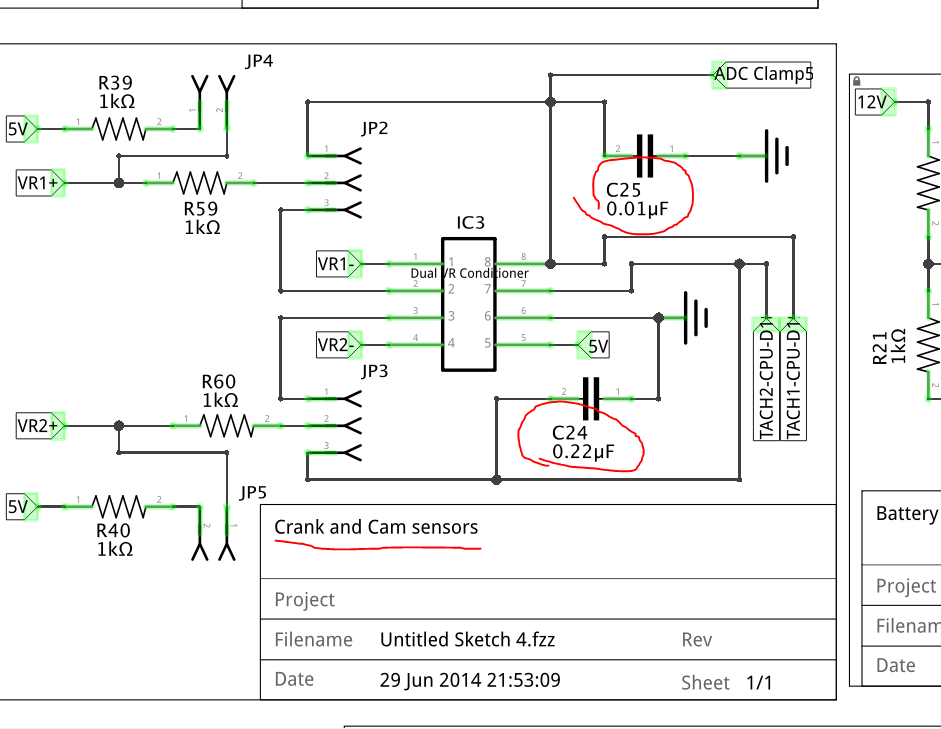
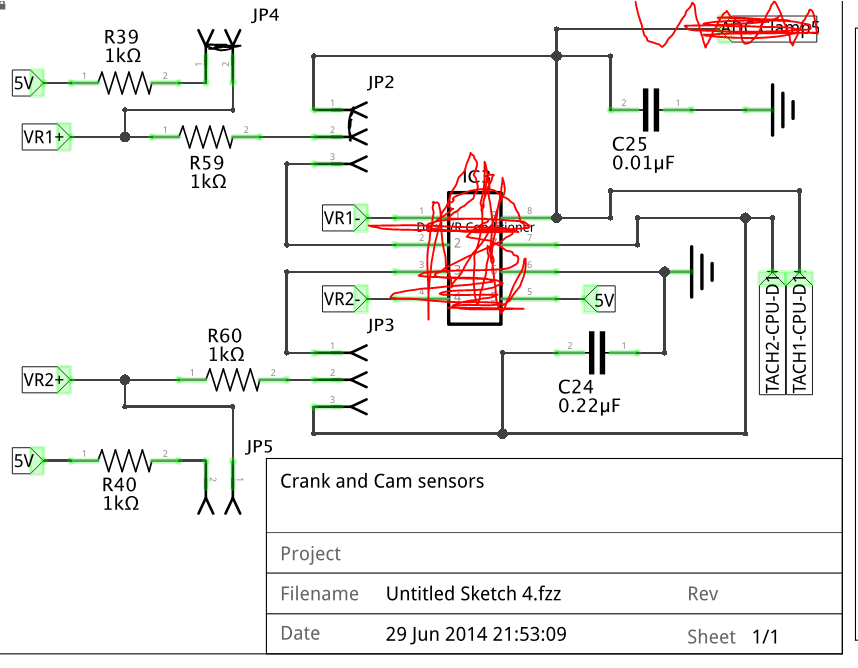
the most correct thing to do would be to probe ic3’s pin8 during run to see if the sensor is behaving and that the adc clamp isn’t doing something it shouldn’t, and then probing ic3’s pin1 to make sure the ic is outputting what its supposed to… but if you don’t have an O’scope you could unsocket ic3 and jump pins 1 and 8 together to bypass it (might have to also jump grounds, unsure where all the jumper pins are going to), theoretically you shouldn’t need to condition a hall affect sensor’s output much; this would atleast show you if the signal conditioner was the problem.
2 Likes
IC3 is optional and not being used. I’M also not using the ADC clamp.
We need to get the job done !
ahh that covers pretty much everything I mentioned.
could you rig up a momentary switch in place of the crank sensor output and just manually pulse it to see if you get spark? or would the speeduino get upset at the slow/uneven pulses?
2nd video; tapping wire to ground