Version 0.16 (?) - work in progress
To add:
- add more IPv6 rules to improve IPv6 network compatibility, like ICMPv6 Router Solicitation / Advertisement, Neighbor Solicitation / Advertisement, FQDN query / reply, Multicast listener, Node information Request / Reply, Who Are You Request / Reply
- screenshots from the firewall rules tab as examples (after adding the IPv6 ICMP rules)
Background
So you want an easy guide for a secure network for home or for a (very) small business? Want to read some accompanying rants, or just simply ignore walls-of-text not related to the actual guide? You’re in luck. I did this post, inspired by other wiki entries from members of the forum, specifically:
-
oO.o’s (unpronouncable circles’) OPNsense Gateway Config
and - PhaseLockedLoop’s Infrastructure Series - PLL’s continued exploration of networking, self-hosting and decoupling from big tech
I’ll try to keep it short, but still explain some stuff on the way using the blur / spoiler tag. The reason behind this post is that I can’t seem to find an easy to follow guide for creating a secure network for home or small businesses with not too many restrictions to link to people who need it, so I decided to make my own.
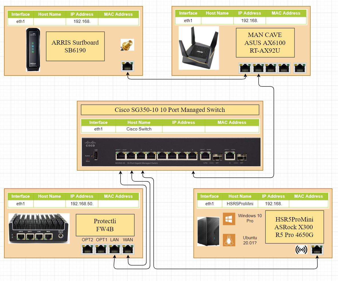
(Potential) Physical Diagram

sorry for the small res
This network will have the ISP modem / router preferably in switch mode / ONT mode / media converter mode, to avoid double NAT, the main firewall, a managed switch, 2 WiFi access points, a PC, a laptop and a smart lightbulb. There’s also a file server / NAS running Samba just as an example for special rules you have to make in the firewall. Add however many devices you want on your network in the limits you have (maximum WiFi connections, maximum switch ports etc.).
(Potential) Network Diagram
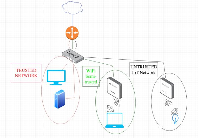
I will be configuring a network with 3 subnets + a WAN connection. The reasoning behind this would be, first of all that’s what I have; second of all, that’s the number of ports (4) most USFF devices come with, so you should make use of all your resources; and third, you should definitely, at the very least have a trusted wired LAN (which could also be the management LAN), a second subnet for WLAN (wireless devices) which can be hacked into, especially if you are using old wireless access points or old routers with no firmware updates and old standards like WPA2 (upgrade to something which supports WPA3), and a third network for untrusted devices, which can be IoT devices (wired or wireless), in which you ought to be using a separate wireless access point for if you can’t have them wired, albeit wired is highly recommended. Again, at the very least a trusted wired network, a slightly trusted network (usually for WiFi) and an untrusted network. The firewall rules will vary depending on how much you trust your WiFi network and how confident you are in WiFi security (which, from my knowledge, you shouldn’t be).
Prerequisites
- An internet connection (or a connection to an adjacent public or private network)
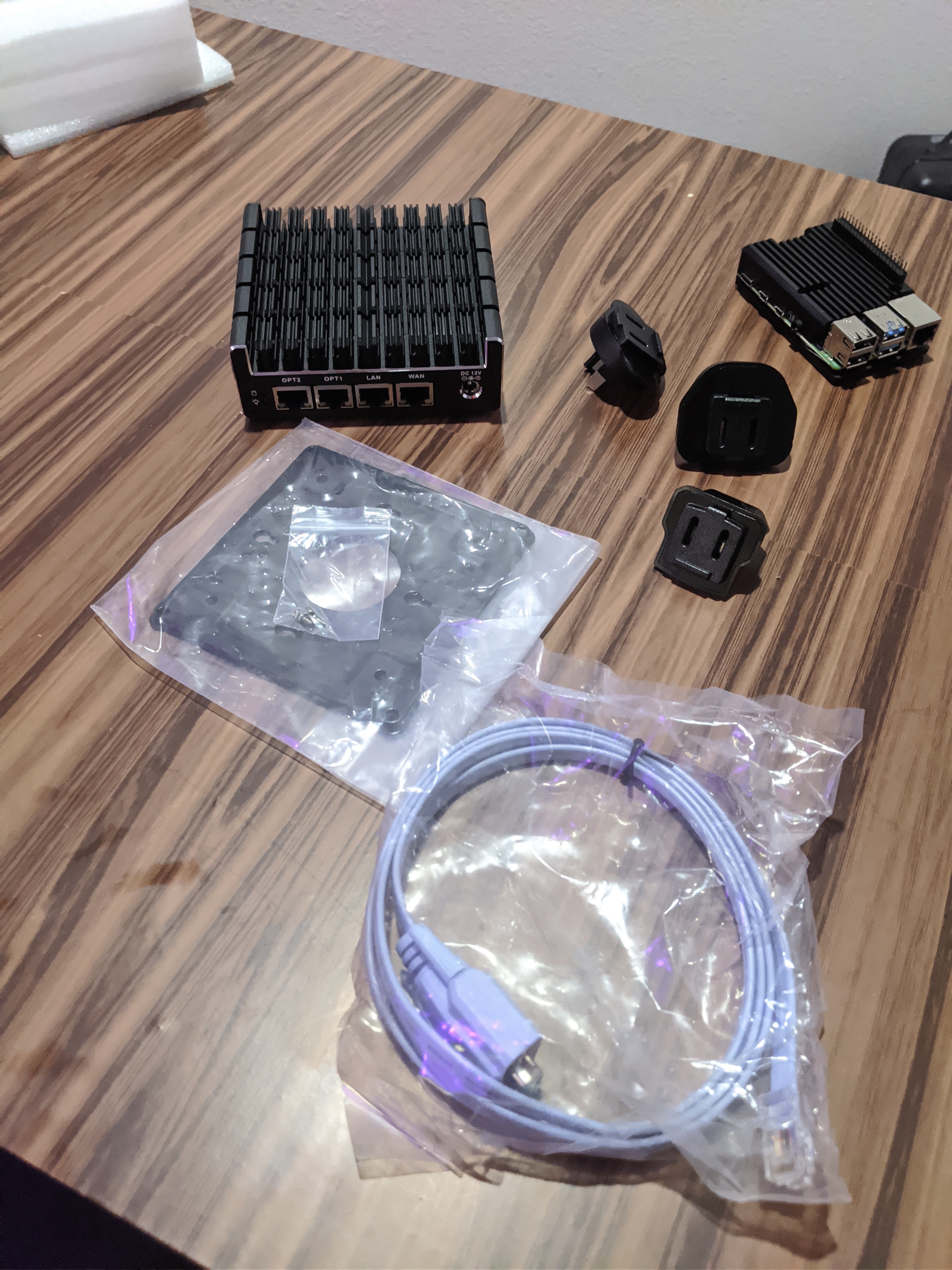
- A router / firewall device with 4 Ethernet (or SFP/+) ports. This can be an old x86 / x86_64 PC with a 4 port Ethernet Adapter, an USFF router / device (like PLL’s Protectli FW4B J3610 box or an ARM / RISC-V / POWER equivalent device that can run the OS of your choice.
- Cables to connect everything (duh)
Add whatever hardware / however many ports you need for your own setup.
I only recommend running FOSS firewalls / routers, so that would be pfSense, OPNsense or a DIY solution using *BSD (pf, preferably OpenBSD) or Linux. FreeBSD has a faster network stack and more hardware support, at the cost of a little more complexity. pfSense is based on it because of that (and a few other reasons). OPNsense is a fork of pfSense and uses HardenedBSD, which is a fork of FreeBSD. If you fancy DIY solutions and minimalism, for home use and even for a small to medium-sized business, OpenBSD is fine. You should go FreeBSD (DIY) or pfSense / OPNsense if you predict the business (or home network, I won’t judge if you got lots of devices and services running at home) will grow too big. IMO, that would be over 100 concurrent devices and / or services or over 300 users for 10 services (so 3000+ connections). But a network this big is beyond the scope of this wiki.
If you like DIY and want Linux, personally I’d go with Alpine, due to its reduced size, hardening and the ability to run from RAM).
Personally I wouldn’t go with *WRT or Tomatoes due to the fact that they usually run on hardware with a built-in not-really manageable switch, so you basically only have 1 (internal) port that you can set VLANs on and which will be applied to all the switch ports from your router (if it even has more than 1 LAN port). You can if you want, but I wouldn’t recommend.
Optional
- A managed switch (highly recommended) or multiple unmanaged switches
- A wireless Access Point or an old router
The old router can be put in bridge / AP mode and be used for wireless only. Here, I definitely recommend you use a *WRT or Tomato firmware for features and (security) updates. But these things are optional and you can definitely have a network with just the main router and 3 devices connected to it (aside from the main Internet connection), with no potential for adding new devices unless you get a switch or wireless AP.
I will do this guide with pfSense, because that’s what I have. I would have done OpenBSD, but I hate distro-hopping in general (unless it’s really necessary) even when I love a certain OS over another, so I use whatever I have.
Aside from the prerequisites, you need a monitor + keyboard + / - mouse and a separate device you can use to remote / serial console into the firewall / router and / or switch for configurations, preferably a desktop PC or laptop with an Ethernet or SFP/+ port. Additionally, you might need a USB to Serial converter + a Serial to Console cable if your managed switch doesn’t come with a built-in USB management port (most newer switches have a USB Mini-B port near the console port). I won’t get into how to connect to your firewall or switch via serial console.
Configurations
Firewall
First prep
First, go to the BIOS / UEFI and check if your device has a “Last State” or “Always On / Power On” feature. This is going to be a firewall, so it’s expected to run 24/7 and should not need any user input to go back online. If it doesn’t, but your device support Wake-on-LAN (WOL), you can set up a device in your network, like a *Pi and make it check its own last state / uptime and the availability of your firewall and set it up to power-on the router. In abscence of that, you can still configure something like a *Pi to use the physical Power button to power on your firewall. This is beyond the scope of this wiki. Following that, install an OS.
Initial port configuration
After you have installed the OS of your choice (again, using pfSense here) on your firewall box, configure the ports as follows (I will start with 0, because that’s what you get in most *nix OS, like igb0, re0, eth0, enpXs0 etc.):
- Port 0 = WAN
Depending on what you’re connecting to, you have to either set a static IP address, get an IP address via DHCP, or set a PPPoE connection. This can be skipped for now and configured in just a moment via the web GUI. - Port 1 = LAN (trusted network)
- Port 2 = WLAN (slightly trusted network)
- Port 3 = UNTRUSTED (untrusted network)
For each network you have to set an IP address on the port and a subnet. These must be different for each port. You should also not give the whole subnet for use by the DHCP server, keep between 30 to 60 IP addresses reserved for static mapping, like the first or last IPs from the subnet. For example, if your LAN subnet is 192.168.12.0/24, give 192.168.12.1 to the firewall port 1 and give the DHCP either the IPs from 192.168.12.30 to 192.168.12.254, or the IPs from 192.168.12.2 to 192.168.12.200. Keep the rest of the IPs either for static IP address configurations on servers, or static DHCP mappings to MAC Addresses. Do this for all the subnets your create, it may save you some hassle later. Do not enable VLANs on the ports, as the switch ports will be set to Mode Access. You can set VLANs on any one port if you need more subnets in the future and use Mode Trunk on the switch, but this goes beyond the scope of this wiki.
Once created, temporarily connect an end-user device to your router, if using Ethernet, preferably using a crossover cable, however most modern devices support auto-negotiation and won’t care if it’s a straight or crossover cable; if using SFP/+, either connect a device that also has a SFP/+ port, or first use a switch in its default configuration and connect your end-device to the switch.
pfSense General Setup
Under general setup, set up a few DNS servers you trust for DNS resolution inside your network. Under DNS Resolution Behavior select the default behavior “Use local DNS, fall back to remote DNS servers” UNLESS you plan on using a separate DNS server inside your network, like a Pi-Hole, in which case you use “local DNS, ignore remote DNS.” That goes beyond the scope of this wiki. Further down, set your timezone and a NTP server (I just use the pfsense pool). We will make use of the default NTP server option in pfSense in just a little.
Firewall Rules
Now go to Firewall → Rules. If you don’t want IPv6, ignore WAN and go to LAN. The order of the rules matters a lot, so be careful about the order.
If you’re not using a dark theme or an extension for dark CSS, you’re a terrible person.
If you want IPv6, you will want to permit your firewall to communicate with a DHCPv6 server, so you have to add in WAN:
Pass: IPv6 UDP ; Source Any ; Port 547 ; Destination This Firewall (Self) ; Port 546
Port 547 is used by DHCPv6 servers and port 546 is used by DHCPv6 clients.
LAN
Add to the end (append) the following:
Block: IPv4+6 TCP/UDP ; Source Lan Net ; Port * ; Invert Match Destination This Firewall (Self) ; Port 53 (DNS)Block: IPv4+6 TCP/UDP ; Source Lan Net ; Port * ; Invert Match Destination This Firewall (Self) ; Port 853 (DNS over TLS)Block: IPv4+6 TCP/UDP ; Source Lan Net ; Port * ; Invert Match Destination This Firewall (Self) ; Port 123 (NTP)
#These are rules to block DNS, DNS over TLS and NTP to anything other than the Firewall. This is what Invert Match is for. To replicate this without Invert Match, you have to first add a rule to pass these 3 ports to the firewall, then block these 3 ports to anywhere else, so we halvened the rules! You have a DNS and NTP server on your network, there is absolutely 0 reasons to use outside services for this on your end-user devices. Note that you need to configure at least NTP on each of your end-user devices manually, as the DNS will be configured by the DHCP server on your devices if you use DHCP and not manual static IP.
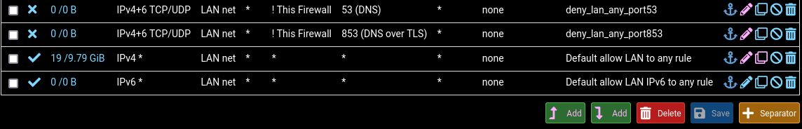
I was thinking while posting this, I will have to upload new pics after I add the IPv6 rules, so things will change, so this will be the only example of rules from pfSense for now. Not to complicated, right? Oh, just realized I didn’t save the rule to block port 123 on the Internet on my trusted LAN. That should go before the Pass IPv4 rule, as mentioned.
Make sure the “Default allow Lan (and ipv6) to any rule” are moved to the bottom otherwise it will allow DNS, DoT and NTP to ourside your network, since they’re the first rules to apply. If you want your LAN (your wired connection) to also be a management network, give it a rule (append / add at the end) to allow it to go anywhere, for the sake and simplicity, like so, then delete the default 2 separate rules:
Pass: IPv4+6 * ; Source LAN Net ; Port * ; Destination * ; Port *
If you don’t want it to communicate with wireless devices and untrusted devices, you can add 2 rules before the Management (allow any) rule to Block Destination WLAN and UNTRUSTED. There are legitimate reasons for wanting to have completely separate networks, however, this is outside the scope of this wiki.
I recommend leaving the LAN as-is for now. Only connect devices you really trust to this network. For example, that could be your main desktop, a *Pi running Pi-Hole, a NAS and a virtualization server.
WLAN
Go to Firewall → Rules → WLAN. Disable or delete any default rules. Here, add:
Pass: IPv4+6 TCP/UDP ; Source WLAN Net ; Port * ; Destination This Firewall (Self) ; Port 53 (DNS)Pass: IPv4+6 TCP/UDP ; Source WLAN Net ; Port * ; Destination This Firewall (Self) ; Port 853 (DNS over TLS)Pass: IPv4+6 TCP/UDP ; Source WLAN Net ; Port * ; Destination This Firewall (Self) ; Port 123 (NTP)-
Block: IPv4+6 * ; Source WLAN Net ; Port * ; Destination This Firewall (Self) ; Port *
#Other than DNS, DoT and NTP, you should not allow any WiFi device from accessing the firewall management interface(s). Adapt this to your preferences, but it is not recommended. At the very least, set up a static DHCP mapping and only allow an individual device to access the management, but again, not recommended. -
Pass: IPv4+6 TCP/UDP ; Source WLAN Net ; Port * ; Destination Single Host or Alias 192.168.x.x ; Port 445 (MS DS)
#This rule is an example of WiFi devices being allowed to access a single IP address from the LAN, only on port 445, which is the secure SMB port. -
Block: IPv4+6 * ; Source WLAN Net; Port * ; Destination LAN Net ; Port *
#This is a rule to block WiFi devices from accessing any device from the LAN. It is highly recommended you do so. -
Block: IPv4+6 * ; Source WLAN Net; Port * ; Destination UNTRUSTED Net ; Port *
#This rule may be optional. If you have things like a WiFi RGB Light Bulb or smart light switches on your UNTRUSTED subnet and want to use a program on your phone to control them, then you should either disable / delete this rule, or more recommended, find the port(s) used by the program to control the devices and allow the WLAN Net to the UNTRUSTED Net on said protocols and ports (usually most of the stuff is controlled via TCP and HTTP commands, but YMMV). Even more recommended is that you have something like a tablet that you only use to control these devices (like a remote control / central control hub) and connect the tablet to the UNTRUSTED network, instead of installing junk programs on your phone and allowing traffic to a network which is supposed to be more locked-down and where there are potentially lots of untrusted IoT devices. -
Pass: IPv4+6 * ; Source WLAN Net; Port * ; Destination * ; Port *
#This rule, at this point (with these exact order of rules), acts as an “allow all traffic to the Internet.” You can modify this rule to be more restrictive and only allow HTTP(S) and maybe SMTP(S) and IMAP(S) ports, instead of allowing Destination Ports Any, requiring 2 to 6 additional rules. Assuming you will connect your phone and probably your laptop to this network, if you don’t have other security requirement or threat model, you should leave this as is.
UNTRUSTED
Go to Firewall → Rules → UNTRUSTED.
This is probably the longest list to block. Depending on your threat model, you may want to severly lock-down this network. In my configuration, I only allowed DNS, DoT and NTP to the Firewall (Self), blocked everything else to Firewall, blocked any to LAN Net except ICMP Echo Reply (ping replies), blocked any to WLAN Net and only allowed port 80 and 443 to the Internet for OS updates. Depending on what Internet-of-Spyware you add there, you may want to make an additional subnet (and thus, add an Ethernet port on your firewall, or use VLANs on one port) just for “very-slightly-trusted-devices” which you should allow access on the Internet on port 80 and 443. On my network, the UNTRUSTED OPT acts as a DMZ, albeit no service is exposed on the Internet there (just a remote backup NAS for security cameras footage from another far location, which connects to that site using Wireguard). This was initially supposed to act similar to a DMZ and host services here which would be available on the Internet, but never got around to that. The rules I set were as follows:
Pass: IPv4+6 TCP/UDP ; Source UNTRUSTED Net ; Port * ; Destination This Firewall (Self) ; Port 53 (DNS)Pass: IPv4+6 TCP/UDP ; Source UNTRUSTED Net ; Port * ; Destination This Firewall (Self) ; Port 853 (DNS over TLS)Pass: IPv4+6 TCP/UDP ; Source UNTRUSTED Net ; Port * ; Destination This Firewall (Self) ; Port 123 (NTP)Block: IPv4+6 * ; Source UNTRUSTED Net ; Port * ; Destination This Firewall (Self) ; Port *Pass: IPv4+6 ICMP Echo Reply: Source UNTRUSTED Net ; Port * ; Destination LAN Net ; Port *Block: IPv4+6 * ; Source UNTRUSTED Net ; Port * ; Destination LAN Net ; Port *Block: IPv4+6 * ; Source UNTRUSTED Net ; Port * ; Destination WLAN Net ; Port *Allow: IPv4+6 TCP ; Source UNTRUSTED Net ; Port * ; Destination * ; Port 80 (HTTP)Allow: IPv4+6 TCP ; Source UNTRUSTED Net ; Port * ; Destination * ; Port 443 (HTTPS)
Here you can add additional rules, like for example, allow 1 device or all subnet to connect to a remote VPN port. I am not using any IoT devices on this subnet, as mentioned, there is just one VM running here that only needs access to the local NTP and DNS server (firewall), HTTP and HTTPS access on the internet for OS updates (it’s a Linux VM) and access on my Wireguard port on the VPN on the internet, which I did not add to this list, as it is highly specific.
Again, add and remove rules to your liking.
Enabling IPv6 (dual-stack)
Important! IPv6 may break some functionalities in your current IPv4 network, because IPv6 is the preferred layer3 stack. Also, stateful firewalls like pf or iptables are causing issues for IPv6 that NAT used to cause for IPv4, so don’t assume IPv6 is the be-all end-all solution to some network applications’ issues. You could allow all traffic to go unfiltered to a host, but that’s not recommended.
Also, of high importance: pfSense and probably OPNsense too have some hiden rules enabled by default to prevent users from killing their IPv6 traffic. I will go through the rules and adding rules manually for IPv6, but keep in mind those may already exist. You can check them using “pfctl -s rules” in the terminal or in the WebGUI → Diagnostics → Command Prompt.
To enable IPv6, go to System → Advanced → Networking tab → check “Allow IPv6” box. Save and Apply configurations.
Go to Interfaces → WAN and under IPv6 Configuration Type select “DHCP6”. Under the same page, go to DHCP6 Client Configuration and select “DHCPv6 Prefix Delegation Size” = 60.
That means that you will be requesting a /60 network. By default this is set to /64. Prefix Delegation is the IPv6 option through which you ask for a bigger network segment. So a /64 is a single network, a /63 could be split into 2x /64 networks, a /62 into 4x /64, a /61 into 8x /64 etc.
So with a /60 Delegation Prefix you will be able to make 16x /64 networks. Reminder that a single /64 IPv6 network is a lot bigger than the whole IPv4 Internet as a whole. Also, there have been reports that some ISPs will only give you the number of Prefix Delegation originally set. Not sure about that, but do keep in mind. Also, the biggest network segment ISPs usually give is a /48, with most of them only offering a /56 at most (again, YMMV). A /60 should be plenty even for the most advanced home network and maybe even for a medium-sized business network in one location (of course, a medium-sized business can outgrow 16 subnets by aggressively splitting networks between departments, which they should).
You may need to check “Send IPv6 prefix hint” (I have) and maybe check “Do not wait for RA” (I have not, it worked without checking it). Depends on your ISP. Save and Apply Configurations. You may need to reboot the router, mine didn’t work until I did so.
Another important note about IPv6 is that an interface has more than 1 IP address assigned to it, usually 2.
These are the Link-Local address, which is used to only communicate only on the local network / broadcast domain and the Global Addressing IP address (i.e. the address that is reachable from the Internet). The concept of link-local address is similar to the 169.251.0.0/16 in IPv4, however, using both the auto-assigned IP and another addressable IP address in IPv4 caused conflict, but in IPv6, this link-local address is a neccessity. The link-local address always starts with fe80.
Also note that in IPv6 there is no concept of broadcast, only multicast. Every IPv6 capable device on the local network (link-local) subscribes to the address “ff02::01” which is the “All nodes on link-local” multicast address. All routers also subscribe to the address “ff02::2,” which is the “All routers” multicast address. “ff01::1” if used for “All nodes on local node.” Similar multicast addresses exist for other services, such as DHCP, NTP, MLD, OSPF etc.
If everything went correctly, you should be presented on the dashboard with both an IPv4 and IPv6 address on the WAN. Alternatively, you can check Status → Interfaces → WAN and see both an IPv6 Link Local and IPv6 Address. If you don’t see the IPv6 Address, again, reboot your firewall either through SSH, or through Diagnostic → Reboot. To check if IPv6 works on your firewall, go to Diagnostics → Ping and ping google.com using IPv6.
Now go to Interfaces → LAN and set “IPv6 Configuration Ttype” = “Track Interface,” then at Track IPv6 Interface select “IPv6 Interface” = “WAN” and “IPv6 Prefix ID” = anything from 0 to f (default is 0).
Save, then go an do the same to WLAN and UNTRUSTED, with the only difference being the IPv6 Prefix ID (you can’t have the same prefix on multiple subnets). Then Save and Apply Changes.
Following that, go to Services → DHCPv6 Server and RA → LAN and go to DHCPv6 Server and enable it. Set “Prefix Delegation Size” = 64 and make sure “Provide DNS servers to DHCPv6 clients” is checked. You can set “Domain name” and “Domain name search” to local or whatever domain or subdomain you own. Save and go to Router Advertisement. I prefer the “Router Mode” = “Managed,” you can keep it as “Assisted” if some devices on your network (Android phones usually reported) can’t get a stateful DHCPv6 IP address and can only use SLAAC with DHCPv6.
Router Mode has flags for different Router Advertisement messages. Managed is just like classic DHCPv4, Router Only only presents the router, Unmanaged lets clients know of the router and lets them use SLAAC, assisted is presentic both Managed and SLAAC flags, usually SLAAC is ignored, unless the device is really dumb and really wants SLAAC, while Statelss DHCP is an option to allow SLAAC address config and present the router (like Unmanaged), but also adds other services, like DNS and NTP which are taken from the DHCP server (so basically DHCP configuration for everything except the IP address).
Save and apply changes.
Managed switch
Every switch OEM have different OS running on them and thus, different tools, commands and terms. I will mostly use the Cisco nomenclature, because that’s what I learned. At home I’m using a rather old HP ProCurve switch. For good op-sec, you shouldn’t divulge any device and / or software / firmware and its version you are running, because that gives attackers enough information to exploit potential vulnerabilities, but I guess do as I say, not as I do, as I have posted on this forum my hardware before, but I’m always running the latest version of everything, so I have at least some trust in my network against script-kiddies, but not against glow-boys and their backdoors side gates.
Once you are inside your switch’s configuration mode, select the ports you want to connect to your router and put them in different VLANs. I prefer having the ports in Access Mode, since I don’t use VLANs on the router ports themselves. For example, put port 1 (LAN) in VLAN 4, port 2 (WLAN) in VLAN 5 and port 3 (UNTRUSTED) in VLAN 6. The VLAN numbers don’t matter, just make sure you remember which one is associated with which network, as you will need to configure others ports that you connect to the end-devices using the same VLANs, depending on their roles. It is highly recommended not to use sequential VLAN numbers and to avoid using the VLAN numbers in this wiki. These are just example to make it easy to understand.
- Set a strong password for your administrative account
- Don’t enable services you won’t use and don’t enable Telnet. If you need remote access, use SSH.
- Set the switch ports you will use for your router and end-devices and put them in Access Mode (e.g. ports 1 to 7, 1 to 3 being used by the firewall)
- Enable Port Security and set a limited number of MAC Addresses on each switch port, preferably just 1 if it will be just 1 device on it. If you will run VMs, you should set it to the maximum number of VMs you will run behind that port, unless you will be doing NAT. The same goes for WLAN and UNTRUSTED, only allow the maximum number of MAC Addresses you know you will have on each port (for example, on WLAN if you only have a phone, a laptop and a tablet, allow 4 MAC Addresses to account for the Wireless AP which is connected to e.g. port 4)
- Enable DHCP Snooping on all ports except the ones that will be connected to your router, e.g. 4 to 24 if you have a 24 port managed switch (more correctly said, set the router ports as trusted by DHCP Snooping, e.g. port 1 to 3 and leave 4 to 24 as untrusted)
- Enable Dynamic ARP Inspection
- Enable IP Source Guard
- Enable PortFast on all ports (unless you use VLANs on your firewall ports)
- Enable BPDU Guard
- Set the native VLAN to something you don’t use (like VLAN 89)
- Do not use VLAN 1 for anything
- Disable all unused switch ports (so 8 to 24) and put them in a different VLAN you are not using (like VLAN 74)
- Disable trunking auto-negotiation
- Optionally, but highly recommended is to add a description on each port (e.g. Port 1 = pfSense LAN, Port 2 = pfSense WLAN, Port 4 = WiFi AP etc.)
At the size of this network, you shouldn’t need Spanning Tree Protocol or other advanced Layer 2 features, so enable all the aggressive security measured mentioned above or their equivalent from different OEMs.
Unmanaged switches
Not much to say other than connecting them to your firewall’s ports and only adding devices to them based on the network you want them to be in. Additionally, you can label them to make it easier to remember which is connected to which network.
WiFi Access Points
Go into your AP configuration, set a static IP address or take its MAC Address and put it in your DHCP server, configure your wireless settings, like WPA2 password, band etc. Not much to say here.
Old routers
If you want to use old routers in AP or bridge mode, go into its web configuration, set an unused static IP address from the network configured on the firewall, disable its DHCP server, configure your wireless settings like WPA2 password, band etc., enable AP or bridge mode, then plug the router into the switch or directly in your firewall’s port using the old router’s LAN port, not WAN port. Depending on the device you are using, the web GUI may or may not be available anymore after enabling AP mode.
Connecting everything up
Since everything is configured now, you can disconnect your end-device from your router and connect everything up as you have configured, e.g.:
- fw port 0 → ISP device (modem, router, ONT)
- fw port 1 → switch port 1 (VLAN 4)
- fw port 2 → switch port 2 (VLAN 5)
Note: you can plug the Wireless AP directly to firewall port 2 if you don’t intend to have additional wired devices plugged to this network. One such use-case for an additional wired device would be having a jump server, which is allowed in the firewall to access certain areas of your other networks. I personally had such a setup, albeit connected to my old router’s switch / LAN port which I used as a jump server to my LAN when my laptop was connected to a VPN which redirected all my traffic, so I had to use local network hackery to access my local resources. - fw port 3 → switch port 3 (VLAN 6)
- wireless AP → switch port 4 (VLAN 5)
- trusted desktop PC → switch port 5 (VLAN 4)
- NAS → switch port 6 (VLAN 4)
- very shady looking IoT device or aditional WiFi AP for untrusted wireless networking → switch port 7 (VLAN 6)
 on OP to get a badge. Any donators?
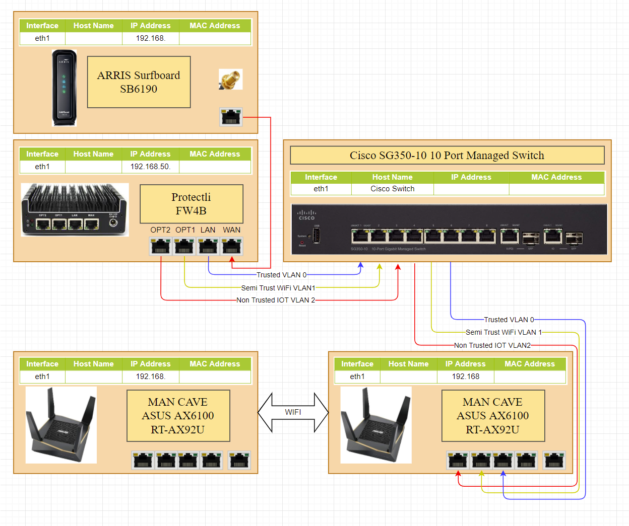
