Since it's the "in" thing right now I figured I'd share the current progress on my dual xeon build, along with the problems I've been encountering along the way and hopefully the solutions.
Parts list:
Motherboard: Dell WN7Y6 (from T5610)
CPU: 2x E5-2680 (2.7Ghz base with 3.5Ghz turbo)
GPU: Zotac GTX970 Amp Omega edition
RAM: 64GB of Hynix DDR3 EEC Reg 1600
SSD: Crucial BX100 120GB
HDD: Western Digital Black 750GB
CPU Coollers: 2x Antec 550LC closed loop coolers
5.25 Drive: Dell 12x Blu-ray drive
PSU: Corsair AX760 (supports and includes the cables needed to power two CPUs)
Case: Phanteks Enthoo Pro
Most of the parts were bought used or were things I had laying around from past builds and RMAs.
I will be using this PC mainly for programing projects, 3D print designing, and as a home theater/gaming PC for my projector setup. My main system is and X99, so this is a secondary system for the most part.
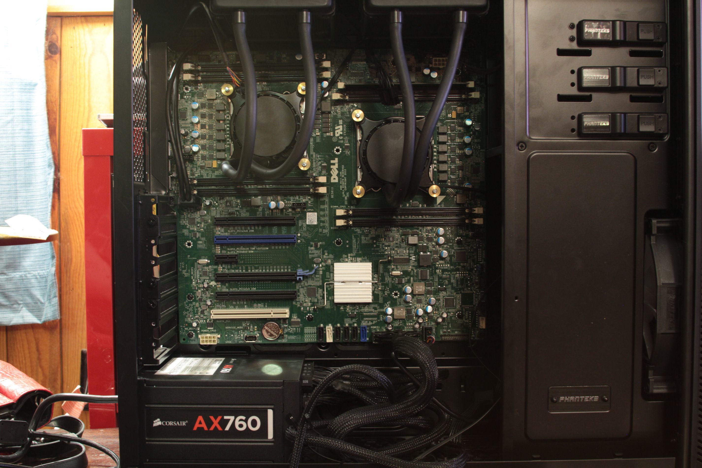
The first challenge was fitting the motherboard into the case. The Phanteks was the one of the only cases I could find that officially supported a SSI EEB motherboard, and the price was right so it was an obvious choice.
All of the standoffs had to be drilled and tapped, and the top PCI slot had to be dremeled out to accommodate for the I/O sticking out beyond the board. I put an old graphics card on the board while marking where the holes had to go to ensure that the pci slots would line up with the case properly. A support bracket for the hard drive cage also had to be removed, but the drive cages can still be used no problem.
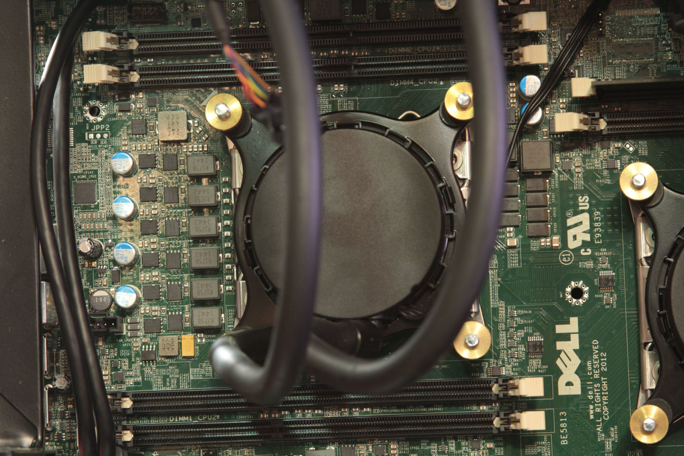
The next problem was mounting the coolers to the board. The Dell board doesn't have the threaded inserts for the standard 2011 mounting. I solved this by using some M10x1.5" bolts with rubber washers running through the back of the board, then I got some knurled brass thumb screws to help dress it up a little.
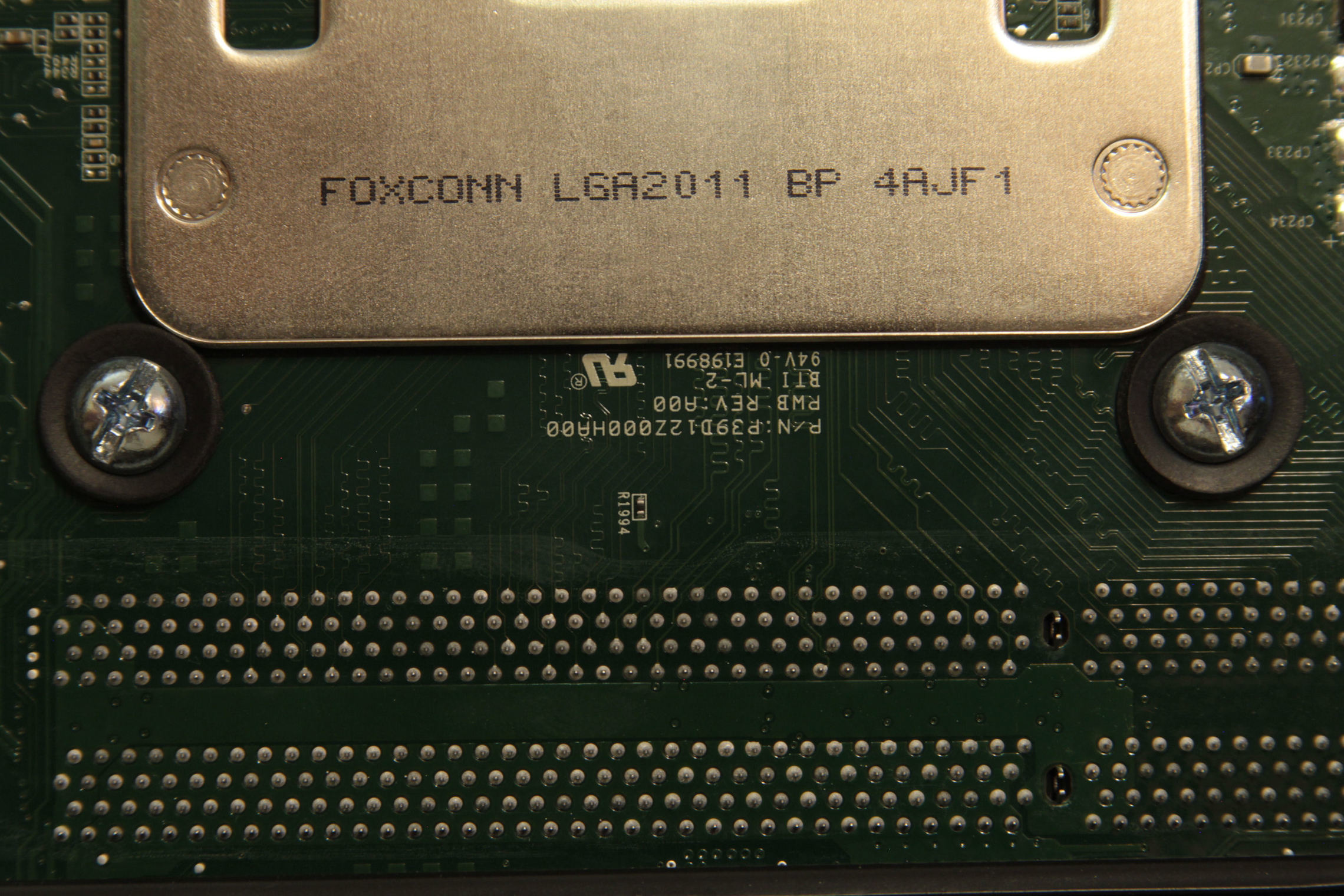
A view of the back side of my mounting solution.
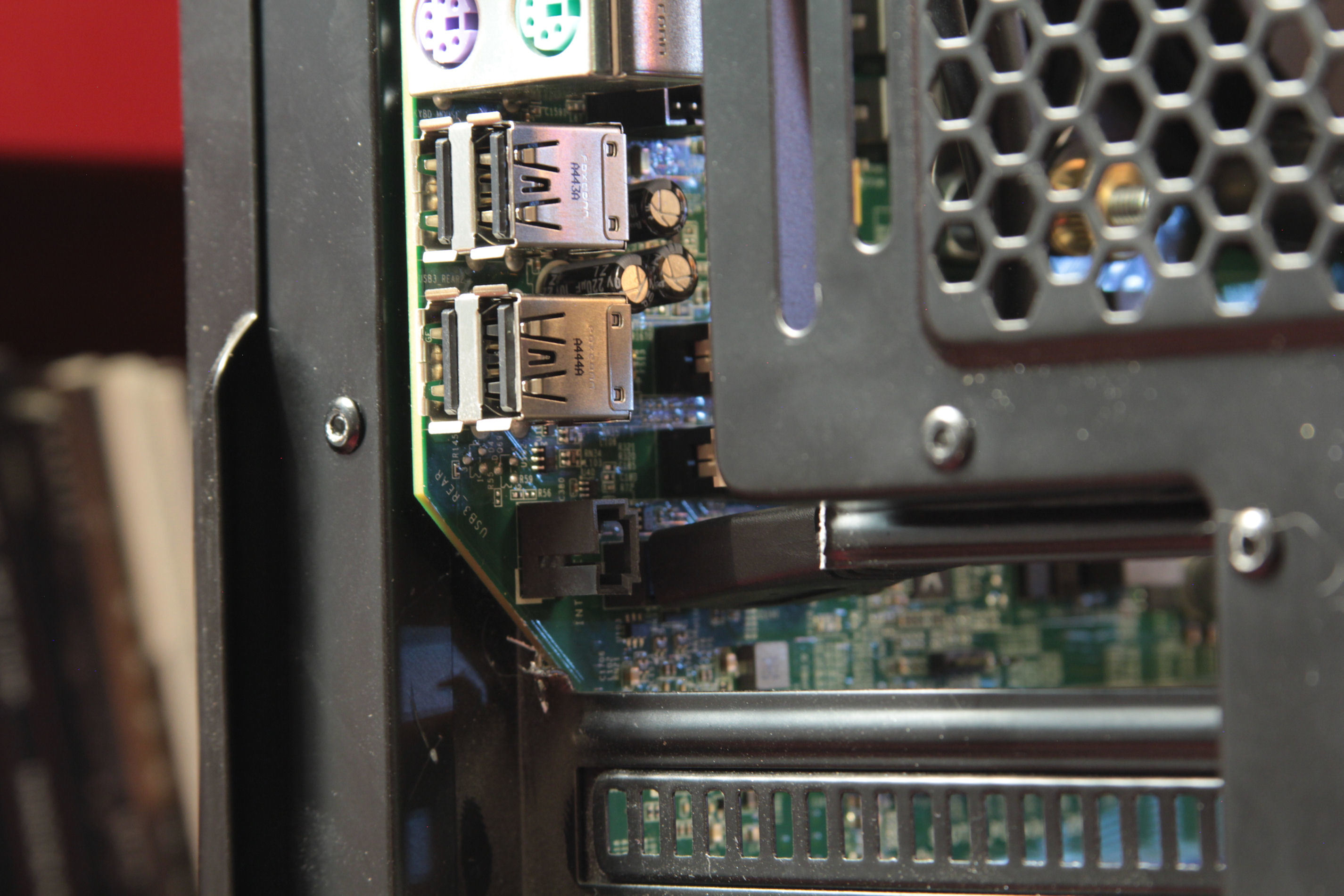
Where I had to cut out one of the PCI slots to fit the I/O. It turned out better that I was expecting with the ports not sticking out past the back of the case. I have plans to 3D print an I/O shield that will also cover the open slot.
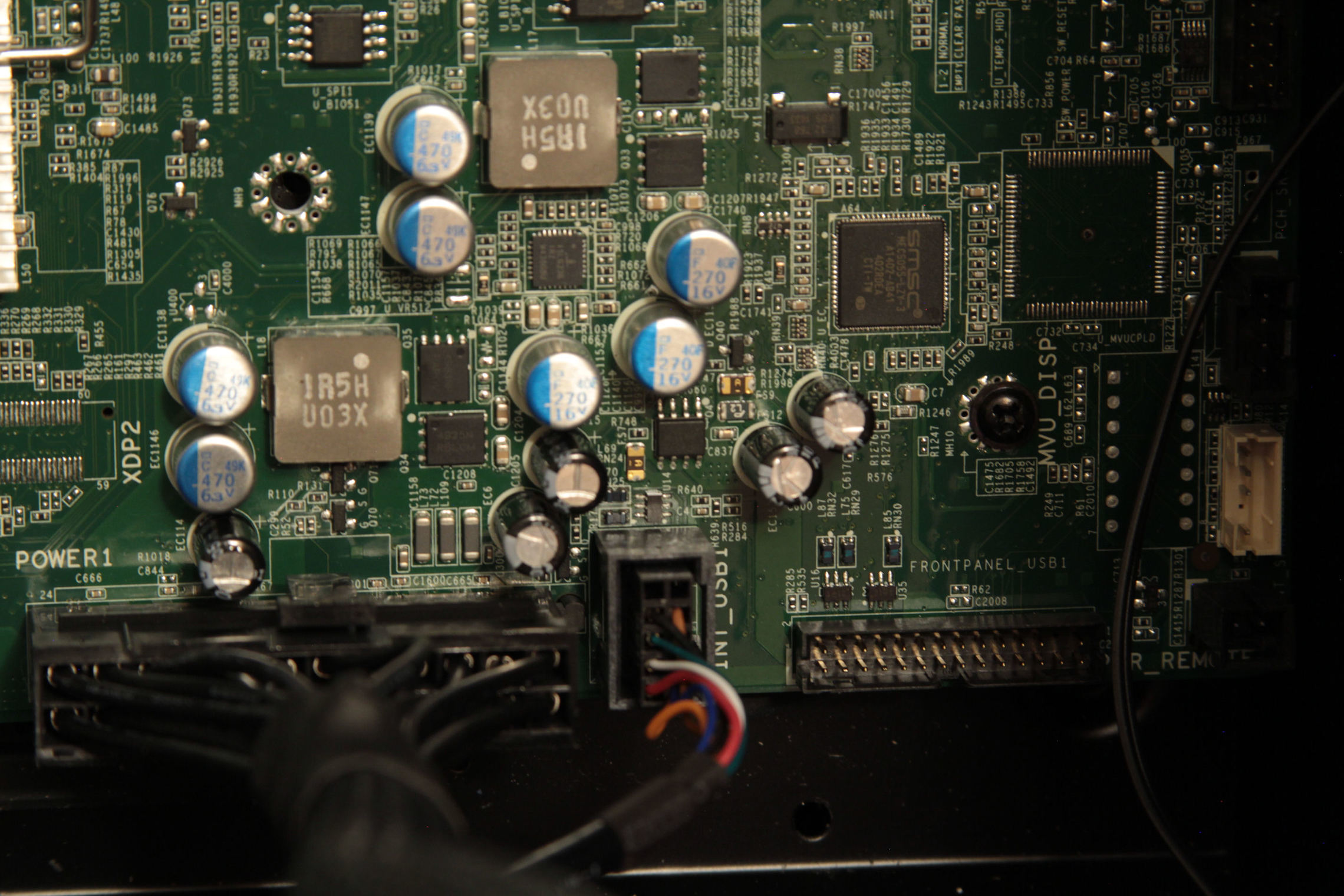
The current problem I am addressing is figuring out what pins are for the power switch, I tried jumping various combinations of pins hoping something would work to no avail. So now I have ordered a front panel from a Dell T5610 so that I can hopefully decipher the pinout, or just modify it to work with the Phanteks case. Along with this I have ordered an adapter to go from Dell's proprietary 5-pin fan plug to a standard 4-pin, and thanks to the Phanteks case including a fan hub I should only need one adapter to let me power all of the fans, and the pumps.
I will update the thread as the parts I've ordered come in, I'm still waiting on the ram to get here from China (though I got a 4GB ecc stick to use for testing in case it takes a while). Hopefully I will be able to at least get the system booted when the front panel I/O comes in, and I plan to make a pinout for the header for anyone that may want to use this board in the future.
Thanks for looking, and if anyone has more insight on the power switch wiring please chime in.
Update:
Here is the pinout for the 24-pin.
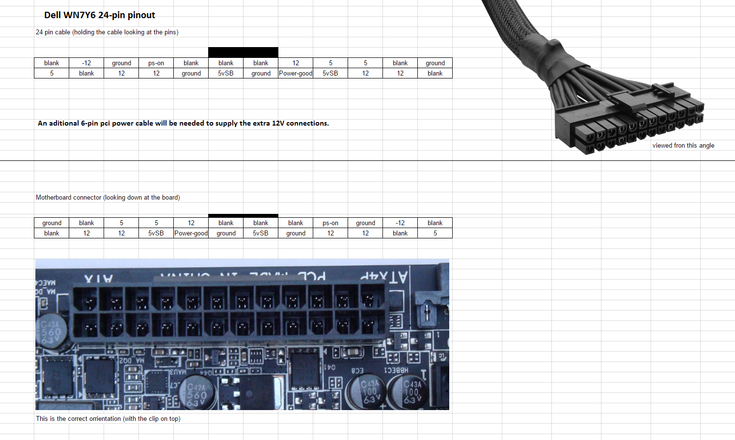
This mod requires the tools to remove atx pins, and an additional 6-pin pci power connector will need to be used to supply the extra 12V connections. At this point I feel it necessary to add that you make these modifications at your own risk! I assume no responsibility for your fried motherboard or other subsequent damage! This mod is not for the faint of heart.
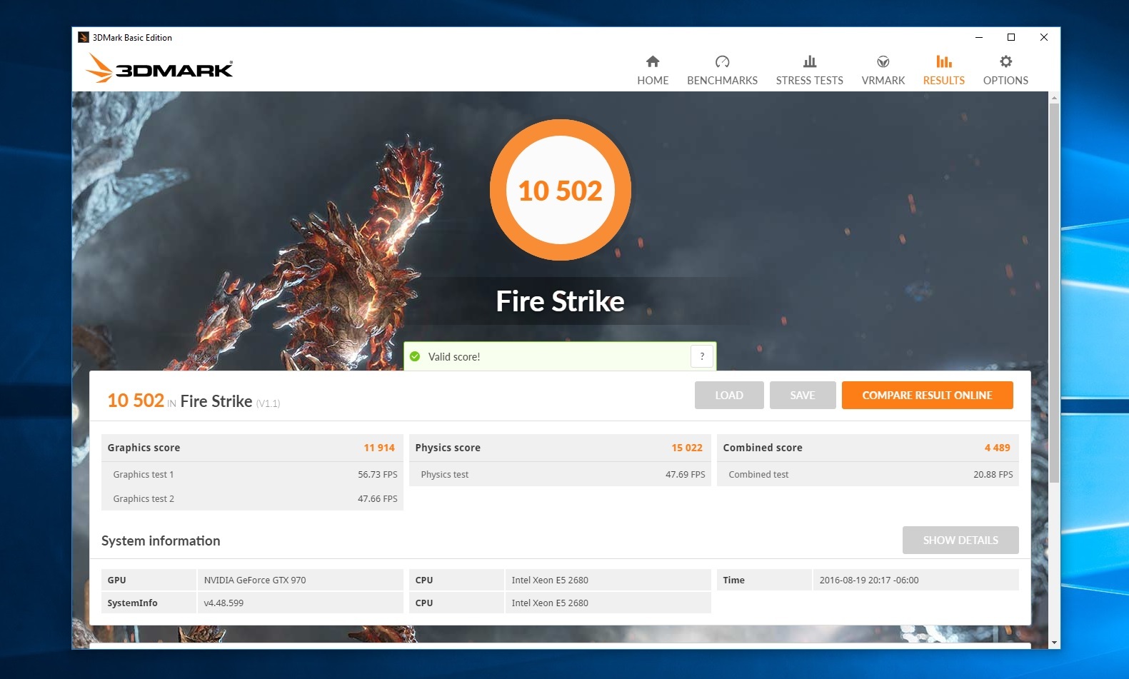
Fire Strike:
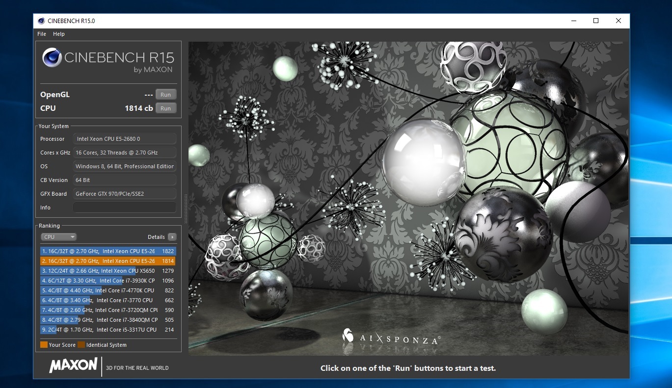
Cinebench R15: