First print uhh failed. Will try again. Have to scale it up about 5% too
2 Likes
Modeling a case is damn hard to get right the first time.
Good luck, Positron seems to have a pretty nice model there.
2 Likes
3 new files.
Easy when you know how… well I’m learning as I go.
Scaling to 105% didn’t work because when I tried to move the holes to maintain the standard screw hole locations, I screwed up the model. That try I consider Revision 3: Learning what not to do.
This is Rev 4. The extra large techs tube.
I made the outside walls 4 mm thicker, left the motherboard tray screws alone and scooped out a 8mm bigger hole in the tube to give you your extra 5% space for wiggle room.
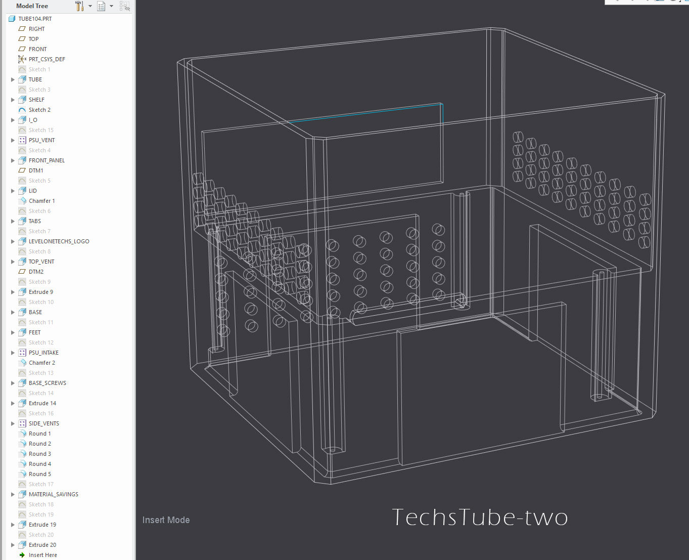
When I revised the first ‘TUBE’ sketch in the model tree, it broke most of the links that referred to surfaces that had moved. I call the tree “The Stack” and I had to go through each operation to reassign reference points.
2 Likes
@wendell
Techs Tube Two Further thoughts: I made a few file revisions to fix mistakes etc.
Tube changes:
-
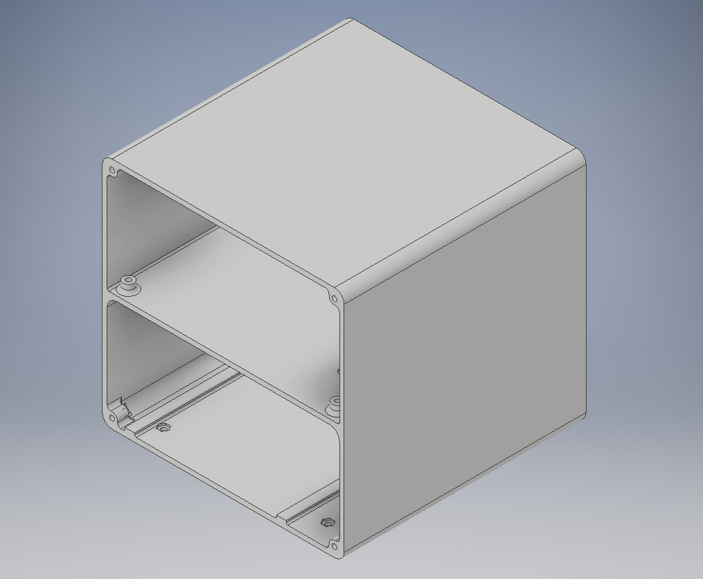
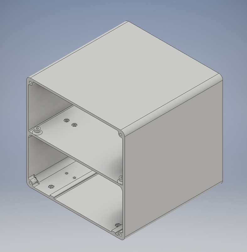
Critical! I had to increase the depth of the rear vent holes because they did not penetrate the thicker lower case walls. If you already printing that, you can drill the holes.
-
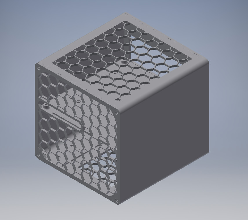
The thin side wall portions of the PSU area will be air intake vents around the base and were rounded. The CPU heatsink fan should turned over to blow up. This will intake air from the sides and bottom.
-
The top was chamfered for appearance.
Base changes:
- I added hollow areas under the feet to save plastic.
The lid had no changes
2 Likes
I have discovered it may be ever so slightly larger than the build area of my MakerBot clone doh
Still investigating tho
I’m trying my hand at designing a case as well.
It will be a three piece design, a middle section (pictured) and two end caps for some slight modularity. The mid section is almost done, I believe the only things left are a slight cutout for cables and some ventilation. The two end caps should be much quicker to do. Also trying to keep the middle within 150x150x150 since that’s the max my printer can do on paper.
1 Like
I dub thee “Part4”.
I believe the case is finished. The mid section is 145mm x 150mm x 150mm, so it should be able to be printed on quite a few printers (possibly including the Replicator clone @wendell).
Things to look out for when printing include the overhangs on the middle section (motherboard standoffs and such) and both end caps have counterbores on one face. The front of the midsection is the side with the notch cut out. Make sure to print four of the feet!
The case is designed to be put together with 16 each of M3 screws and nuts. Screws should be 10mm, although 12mm should work as well. You’ll need screws for the SSD and PSU as well.
Mid section
Front
Back
Foot (at max zoom)
EDIT:
Added modified mid and front to make a slightly easier print.
Mid
Front
7 Likes
Hey @Positron and @w.meri Thank you both for working on this.
I will probably get another 3d printer soon that can do a better job printing these .
So far the printer can’t make it through the print without something weird happening. I should probably find newer software than replicatorg lololol
3 Likes
My printer has a warped bed, so I haven’t even been able to test these out myself.
I should probably test @Positron’s first since his actually looks like a commercial product  Although I would like to source an STX motherboard first
I am glad to see i am not the only one planning something like this >< I have been working on a pc case with many printed parts. My next project was probably going to be itx or a console case swap. Keeping this around and following!
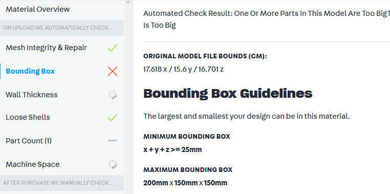
Just let me know what changes you need. It appears to be too big.
I can probably cut the model into 4 L-shaped pieces.
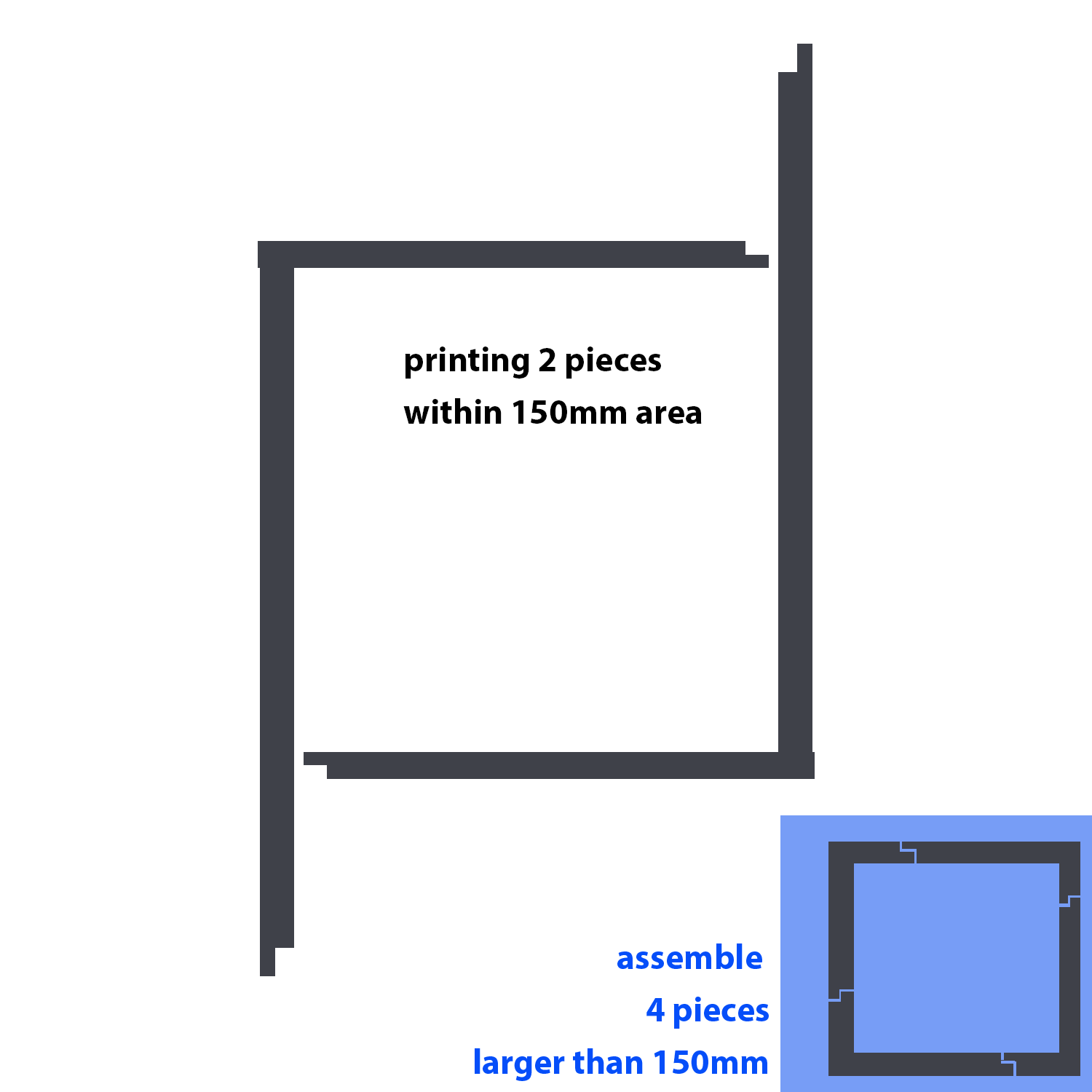
Shapeways wants $282 to print it, but it too big for them also.
I could give printing it a go. I have 200x200x200 area.
1 Like
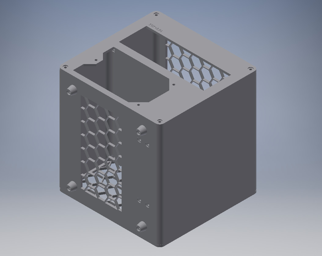
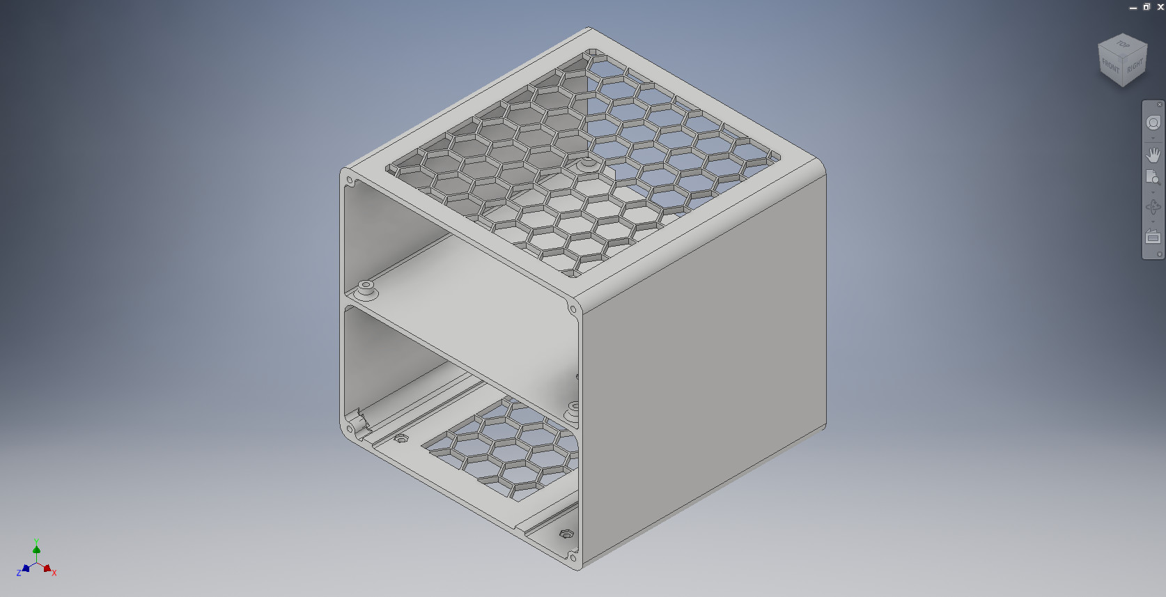
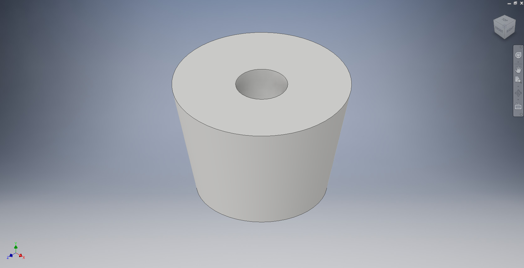
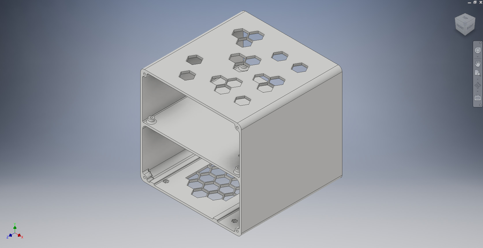
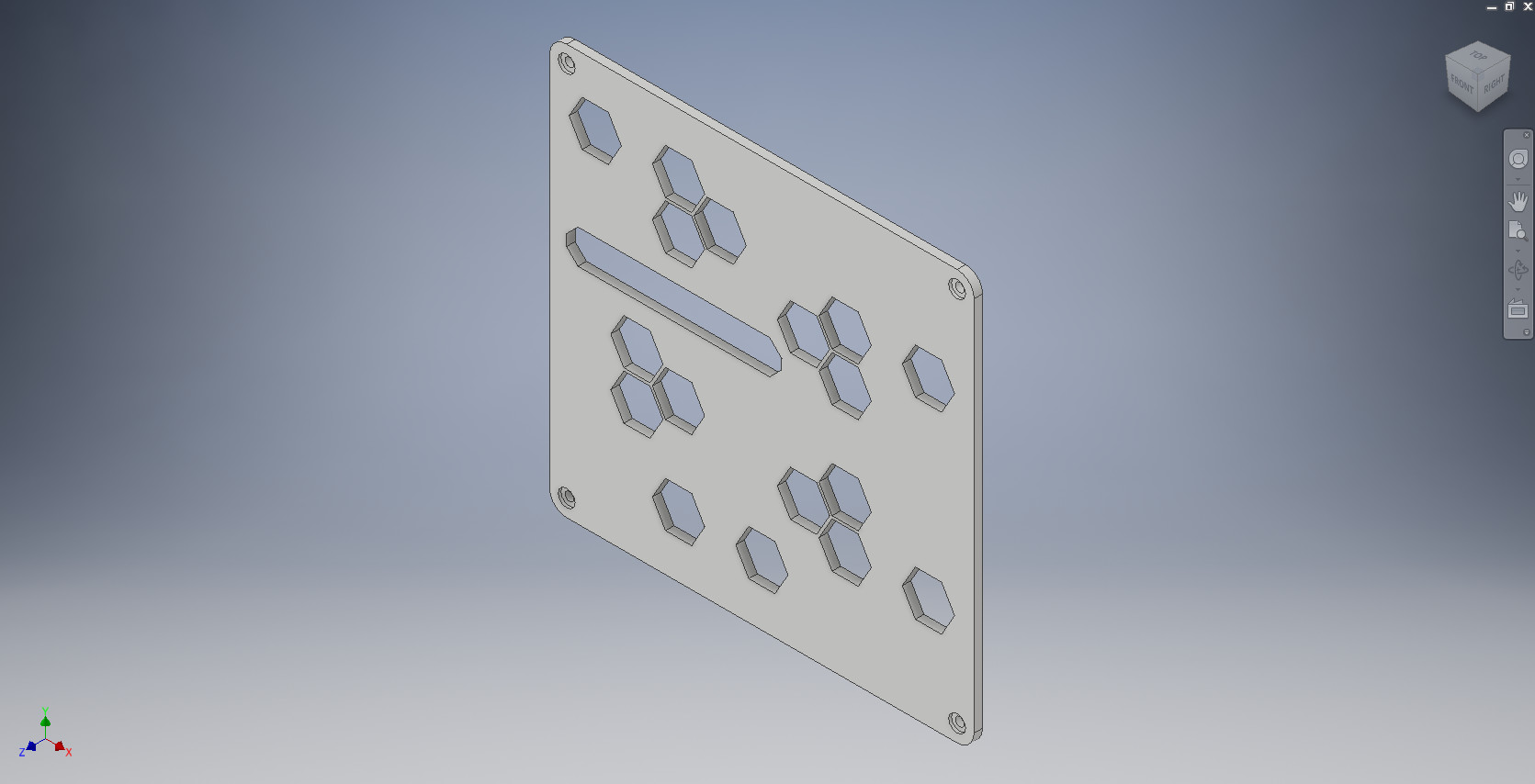
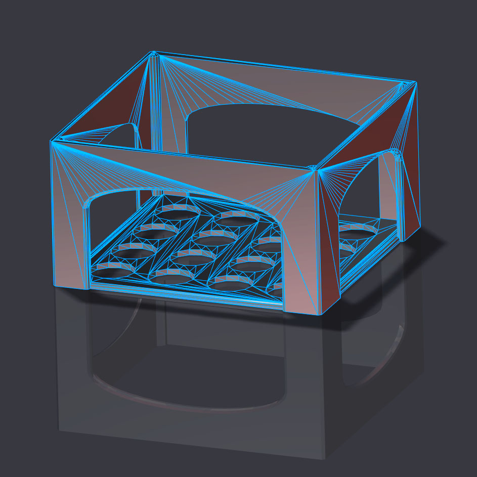
@wendell I made a STX test bench that fits within the typical 150mm x 150mm limit.
It has room inside for a 75mm tall PSU. The height was a guess and easy to change.
3 Likes
75mm should be plenty for SFX power supplies, the SFX specs have them at 63.5mm tall.
Looks good!
I really need to get my printer functioning…
1 Like
Only problem with that is the arches will need supports for the angles beyond 55° in all likelihood.
That part is going to be rough. A more angular design with a 45 would be tons easier. Most printers struggle beyond that. Some of the best can only do like 60.
1 Like
Not if you’ve spent any time calibrating bridging settings.
I was able to keep clean bridging at ~100mm/s on a shitty diy Delta, with normal print speed of 250mm/s.


The max extension out of existing parts is less than a cm. Yes, each of these single runs in a nicely configured slicer will be a short unsupported bridge.
All I’m sayin is if you need heavy support for that, your print settings need some love.
I’m not talking about the last layer of the arch being a problem. If you can make it to that layer without trouble then more power to you. The problem as I see it is the overhang of the arch. I don’t believe it wouldnt sag during printing. Feel free to prove me wrong. I’m sure Wendell would appreciate the part if you sent it to him.
If it were me I would just support it. I would give it a go but I need new glass for my setup. My printbite surface is destroyed.
Ah, I understand what you’re saying. I guess if the layer time is too quick you’ll get curling edges as you print the arch, which could lead to some nasty droop or bad texture.
Are you slicing with s3d? I’ve found the layer speed tool when layers are too quick is a pretty huge boost for features like this.
Also I’d love to give it a run, but I just moved and the delta needs calibration. If I get home early enough I’ll give it a run, but otherwise might have to wait til the weekend.