0xDE57's Electronics Blog

Hello! Inspired by some other electronics blogs here, I figure why not start one too.

There are plenty of electronics projects I have been wanting to tackle for fun and learning. Some projects I have already finished and I might do a couple back log posts. Others I have started progress on or abandoned that I may revive or revisit. And of course some new things I’ve not started yet.

Here is my homelab. I thought maybe I should clean up first before taking a picture, but nah…here is my current chaos:

My favorite thing learning about electricity is that every time I begin to get the illusion that I understand it, reality steps in with some deeper / more nuanced physics that shatters my intuitions and breaks my brain.

Posts to come Soon^tm

9 Likes

Welcome to the club :slight_smile:

Yes, spread the honest reality of “just trying out this one thing”.

2 Likes

I’m definitely interested in seeing more random DIY action. There’s that whole saying to the effect of “A cluttered desk signifies a cluttered mind, so what does an empty desk signify?” Plus I always think of the workbench on The Woodwright’s Shop and how amazingly talented that guy is with hand tools. Let the chaos commence!

2 Likes

Built this a while ago. This is my cheap version of the “Elektrosluch”. An open source electromagnetic listening device. It uses a couple inductors as microphones fed into an op amp.


Credit: GitHub - LOM-instruments/Elektrosluch-DIY


I had accidentally ordered the surface mount (SMD) part instead of the through hole. I had to solder some tiny extension legs…


As you can see I am expert solderer…


Here it is listening to some various things (accidentally recorded mono):
(file too big, had to put it on the tube)

You can find roughly where certain components are like the CPU and radios(wifi/bluetooth/cellular). You can hear the CPU on the phone ramp up when touched and relax into a lower power state when the screen is off. You can also detect live AC in the walls, you’ll get that ~50/~60hz hum. Lots of interesting things to listen to.

Lessons learned:

  • pay attention to the IC package type
5 Likes

Might also do the odd small appliance repair here too. Like this electric kettle for example.

This is the third kettle I’ve had fail prematurely (6m-1y) in the exact same way, regardless of price/brand as they as all seem to have pretty much the same base and connector mechanism:

The failure: the center pin pops out not making contact with the base, kettle no turn on.

I think the problem when the kettle is full of water its heavy, so the repeated slamming onto the base during regular use is what is knocking out the pin.

The repair: first time I used super glue. This gave me another few months, but failed again so clearly not sufficient. There’s not much material/meat to it so I just filled it 2-part epoxy this time.

Probably not UL rated anymore but now its working and I have my tea so that’s all that matters.

Another potential solution might be to sand down the plastic on the inner ring on the base a little so the center pin can’t smack against it when setting the kettle on it. Seems like a poor design imo.

Lessons learned:

  • nothing’s made to last

Not really a new lesson… Sometimes I make 2 - 5 cups of tea a day so maybe I’m the problem :slight_smile: but still I feel like things should not fail this quickly.

4 Likes

You shall adjust user behavior a bit. Sounds like half of the cause is “user error” :grinning:

Btw these electric coupling structures have “de facto” standard sizes generally usable in most electric kettles. Very likely you could buy one new on Aliexpress. There are a lot so much harder to pick a good make.

1 Like

b-but i don’t wanna adjust… u adjust. the world should conform to MY expectations! /s

huh they’re cheap, I could keep a couple extra in stock. thanks!

2 Likes

Lasers are fun. Inspired by styropryo and kipkay back in the day.

I’ve made a couple simple LM317 based drivers and converted nerf guns into lasers housings.

This is the first one I made out of a nerf “jolt” model; red 650nm@300mA:


Powered by a couple 18650’s externally (because too big to fit) via a usb port ripped off some dead device.

It features a trim pot for adjustable output, and an “overclock” button which basically adds an extra resistor in parallel to overdrive the diode a little bit beyond its spec sheet. But not too much because diodes are easy to kill. Just makes lighting a match or popping a balloon a little quicker. Being able to turn down the output to safely observe the focus is really handy. With laser safety goggles obviously, I like being able to see.


I tried doing a video essay type thing for second one I built, a green 520nm@100mW. I’m not very happy with how the video turned out…I don’t much care for video editing and am not a youtuber. But the laser itself came out great. It’s pretty much the same thing as above circuit but different resistor values for tuned for this diode. This version houses the batteries internally where the dart loading mechanism used to be and I was able to hook up the original trigger!

Lessons learned:

  • don’t connect a diode to an already powered up circuit during testing. this can introduce a voltage spike that kills the diode. ask me how i know…

Future plans:

  • RGB laser! a separate red, green and blue lasers fed into some optics to make one beam…in theory… todo: research beam combining mirrors and optics
3 Likes

OpenDrumLights: Revival

The project: RGB drums! LED strips within the drum heads that are triggered when hit. I have a friend who is a drummer and wanted his drums to light up. Commercial versions exist but they are not that cheap and offer limited customization. So we figured why not try to DIY?

Goals:

  • programmable RGB, set any drum to any color
  • ideally a simple UI for the drummer to select colors / patterns, per drum. Stretch: perhaps per song / set?
  • 4 inputs(sensors) and outputs(lights) → 4 drums: kick, snare, tom 1, tom 2
  • MIDI trigger to feed into DAWS or software of choice
  • robust enough to take on stage (handle being plugged and unplugged during setup/teardown)
  • simple enough to take on stage
  • Stretch: DMX support?

I started this project a while ago and moved 2 times so it’s in rough state due to said moving.

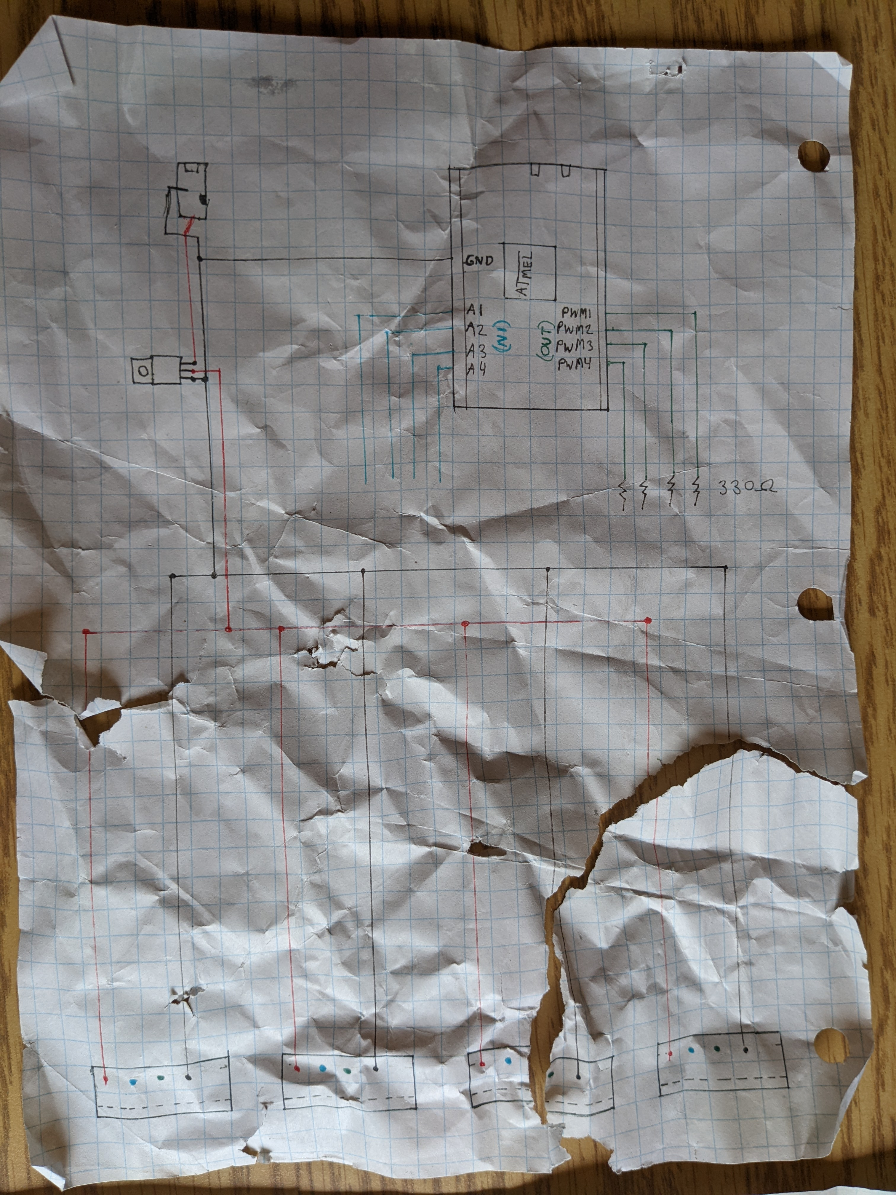
The moving was not kind to my documentation either:

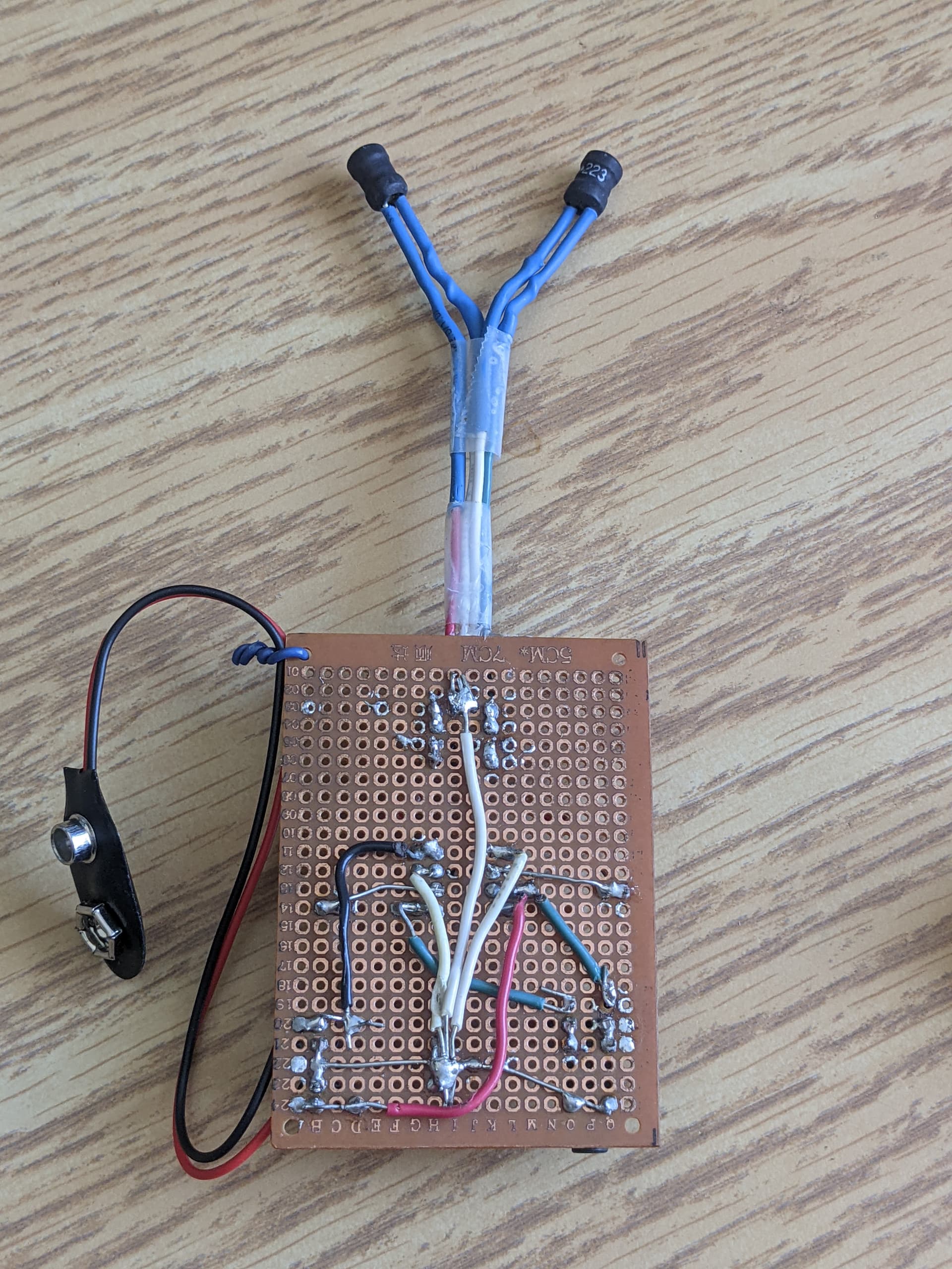
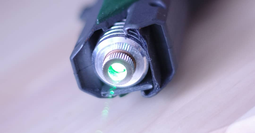
Using an Arduino as the brains. For triggers I chose some cheap piezoelectric sensors to detect vibration. The prototype uses paper plates as placeholder drums. For LED strips we choose individually addressable RGB strips: WS2812B

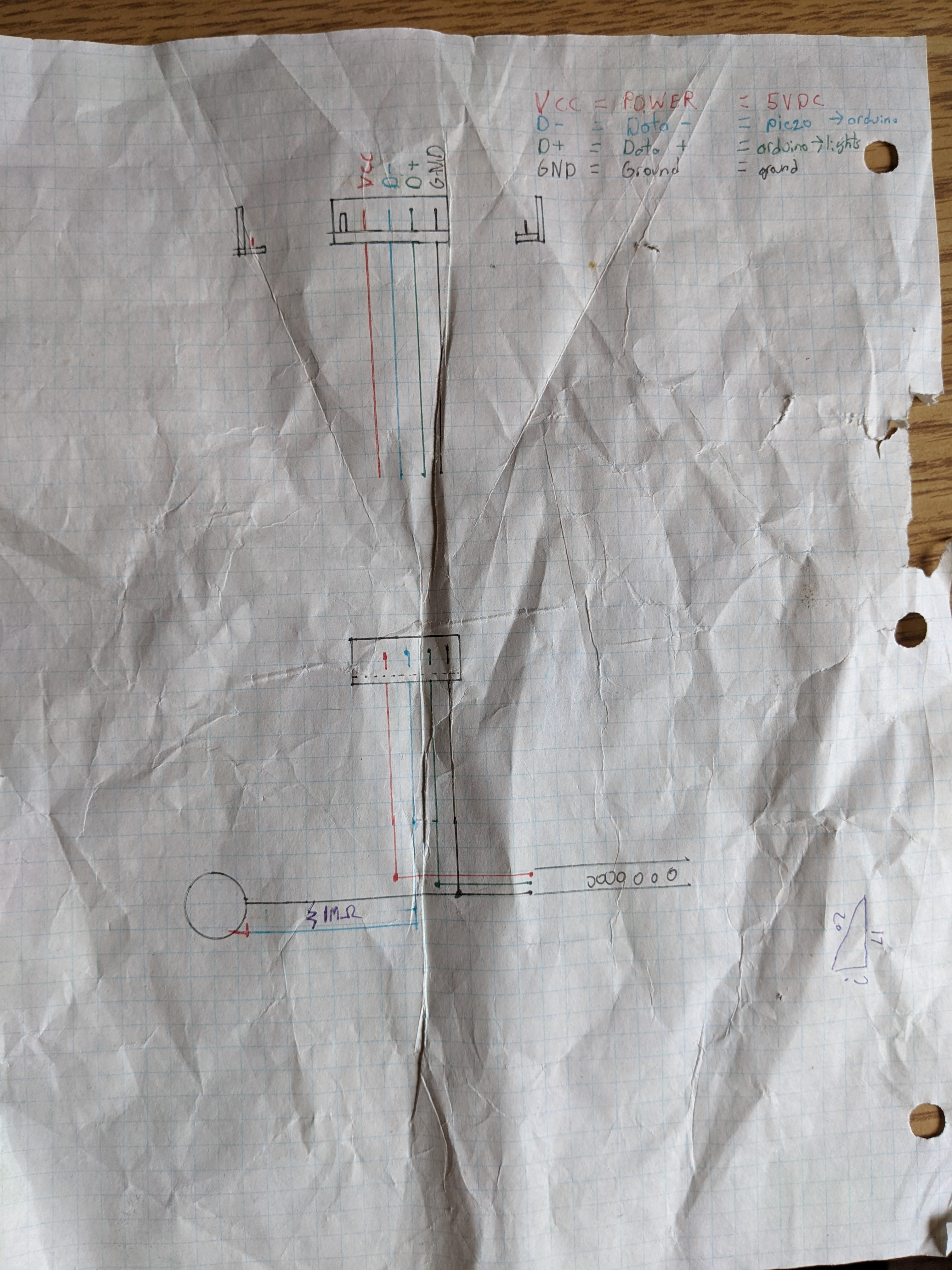
Figured I could use a USB-like format for each drum:

  • VCC = 5VDC
  • Data - = peizo → arduino analog in
  • Data + = arduino PWM out → lights
  • Ground = Ground

Arduino can put out 5v but not enough current to drive the strips. So external additional power is required. NOTE: ground from external power must be tied to arduino ground, otherwise lights flicker and weird noisy circuit. Common ground!

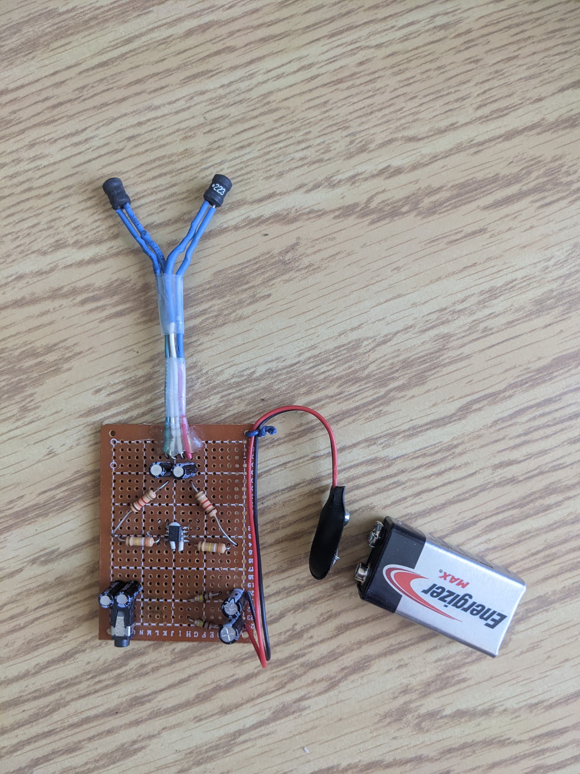
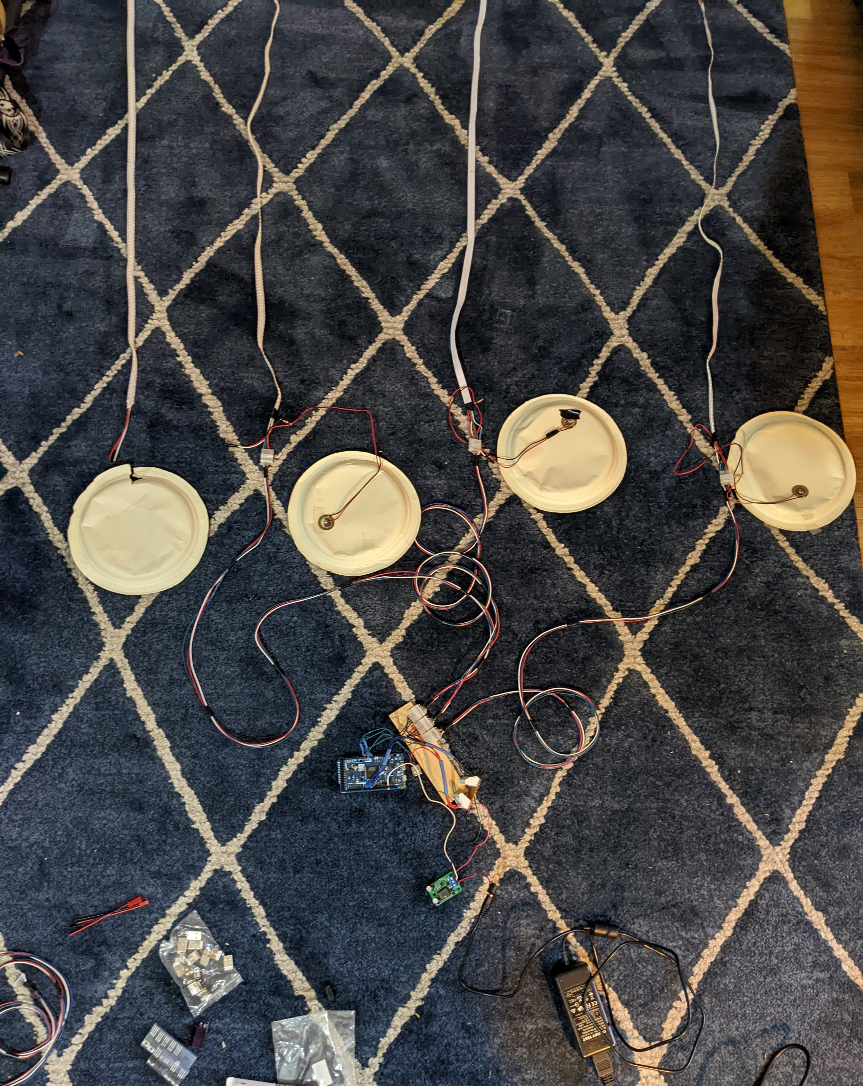
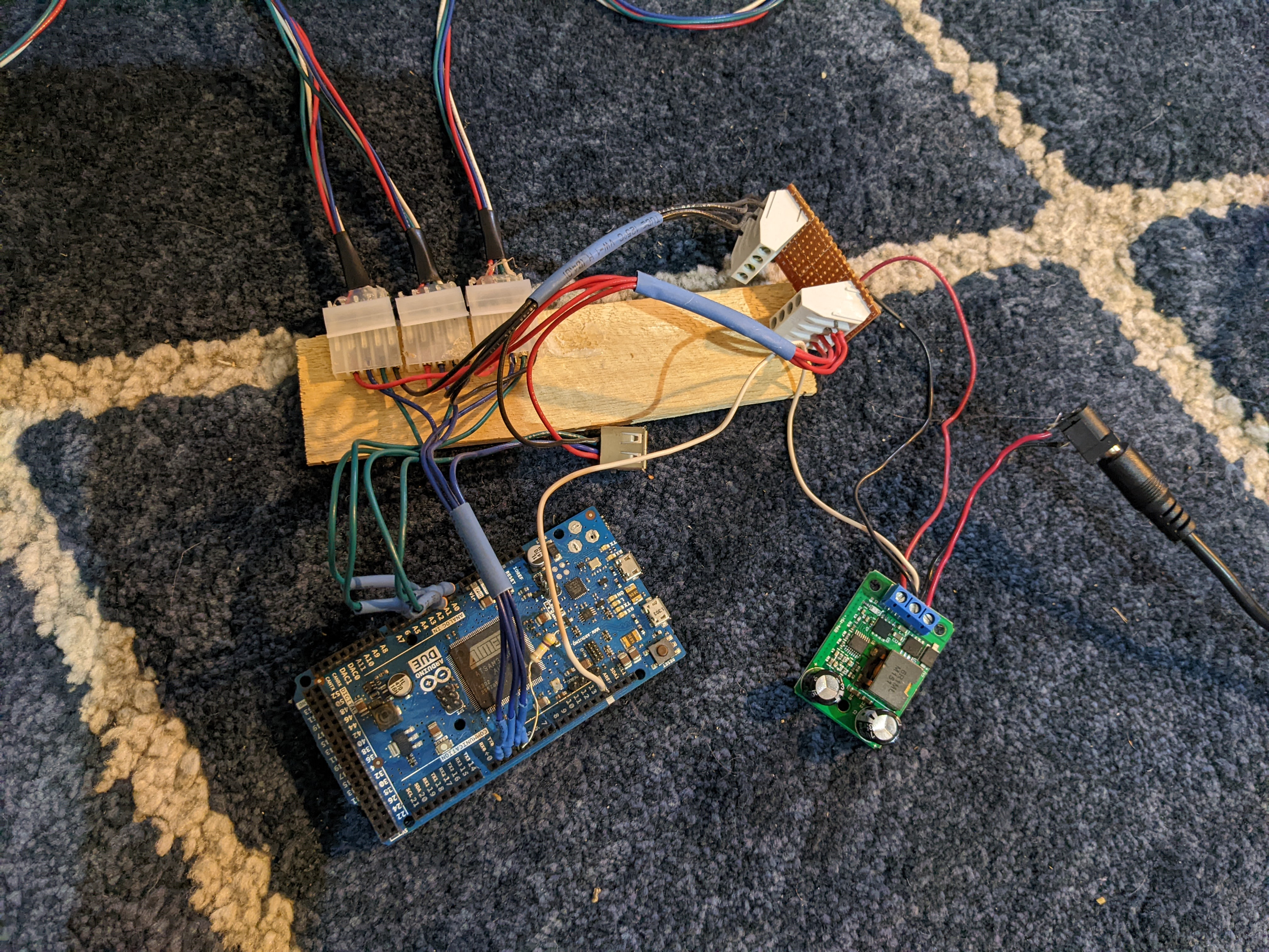
If it looks like a bit of a hacky mess, well it is…but it worked at one point!

Here is a test demo hooked up to a single drum.

Then I hooked up all 4 strips. Success! until the lm317 let out the magic smoke… turns out LM317 is only rated for about 1.5A…

I found that the WS2812B which draw about ~60mA @ 5V per led (white & full brightness). Using 4 x 144LED/M (LED per Meter) strips our worst case scenario is 60mA * 144 LED’s * 4 strips = ~3.4A.

So worst case scenario: 12v supply → 12V-5V=7v. Power = 7Vx4A = ~28W dissipated as heat. Ouch. But that’s with all on all the time. Realistically only a couple strips are on at a time as they are triggered.

So I switched to a buck converter that can handle 5V @ 3A-5A out.


The prototype code is pretty simple. 4 analog pins to read the peizo, and 4 PWM pins out to control the lights:

#include "MIDIUSB.h"
#include "FastLED.h"

//peizo inputs
#define analogIn1 1
#define analogIn2 2
#define analogIn3 3
#define analogIn4 4
#define threshold 100
int val1 = 0;
int val2 = 0;
int val3 = 0;
int val4 = 0;

//led outputs
#define pwmLEDout1 2
#define pwmLEDout2 3
#define pwmLEDout3 4
#define pwmLEDout4 5
#define NUM_LEDS 150
CRGB leds1[NUM_LEDS];
CRGB leds2[NUM_LEDS];
CRGB leds3[NUM_LEDS];
CRGB leds4[NUM_LEDS];


//midi outputs
void setup() {
  Serial.begin(9600);
  pinMode(pwmLEDout1, OUTPUT);
  pinMode(pwmLEDout2, OUTPUT);
  pinMode(pwmLEDout3, OUTPUT);
  pinMode(pwmLEDout4, OUTPUT);
  FastLED.addLeds<WS2812B, pwmLEDout1>(leds1, NUM_LEDS);
  FastLED.addLeds<WS2812B, pwmLEDout2>(leds2, NUM_LEDS);
  FastLED.addLeds<WS2812B, pwmLEDout3>(leds3, NUM_LEDS);
  FastLED.addLeds<WS2812B, pwmLEDout4>(leds4, NUM_LEDS);
}


void loop() {

  //read inputs
  val1 = analogRead(analogIn1);
  val2 = analogRead(analogIn2);
  val3 = analogRead(analogIn3);
  val4 = analogRead(analogIn4);

  //drum 1
  if (val1 > threshold) {
    for (int i = 0; i < NUM_LEDS; i++) {
        leds1[i] = CRGB::Green;
      }

    noteOn(0, 48, 100);
  } else {
    for (int i = 0; i < NUM_LEDS; i++) {
      leds1[i] = CRGB::Black;
    }

    noteOff(0, 48, 100);
  }

   //drum2
  if (val2 > threshold) {
    for (int i = 0; i < NUM_LEDS; i++) {
      leds2[i] = CRGB::Green;
    }

    noteOn(0, 49, 100);
  } else {
    for (int i = 0; i < NUM_LEDS; i++) {
      leds2[i] = CRGB::Black;
    }

    noteOff(0, 49, 100);
  }

   //drum 3
  if (val3 > threshold) {
    for (int i = 0; i < NUM_LEDS; i++) {
      leds3[i] = CRGB::Red;
    }
    noteOn(0, 50, 100);
  } else {
    for (int i = 0; i < NUM_LEDS; i++) {
      leds3[i] = CRGB::Black;
    }

    noteOff(0, 50, 100);
  }

  //drum 4
  if (val4 > threshold) {
    for (int i = 0; i < NUM_LEDS; i++) {
      leds4[i] = CRGB::Blue;
    }

    noteOn(0, 51, 100);
  } else {
    for (int i = 0; i < NUM_LEDS; i++) {
      leds4[i] = CRGB::Black;
    }

    noteOff(0, 51, 100);
  }

  FastLED.show();

  //serial debug
  Serial.print(val1);
  Serial.print(",");
  Serial.print(val2);
  Serial.print(",");
  Serial.print(val3);
  Serial.print(",");
  Serial.println(val4);
}

void noteOn(byte channel, byte pitch, byte velocity) {
  midiEventPacket_t noteOn = {0x09, 0x90 | channel, pitch, velocity};
  MidiUSB.sendMIDI(noteOn);
}

void noteOff(byte channel, byte pitch, byte velocity) {
  midiEventPacket_t noteOff = {0x08, 0x80 | channel, pitch, velocity};
  MidiUSB.sendMIDI(noteOff);
}

todo: de-bounce inputs

The threshold would be the trigger value in this case. How sensitive should the sensors be to trigger. We don’t want the vibrations from adjacent drums to falsely trigger.

Libraries:

  • FastLED
  • MIDIUSB

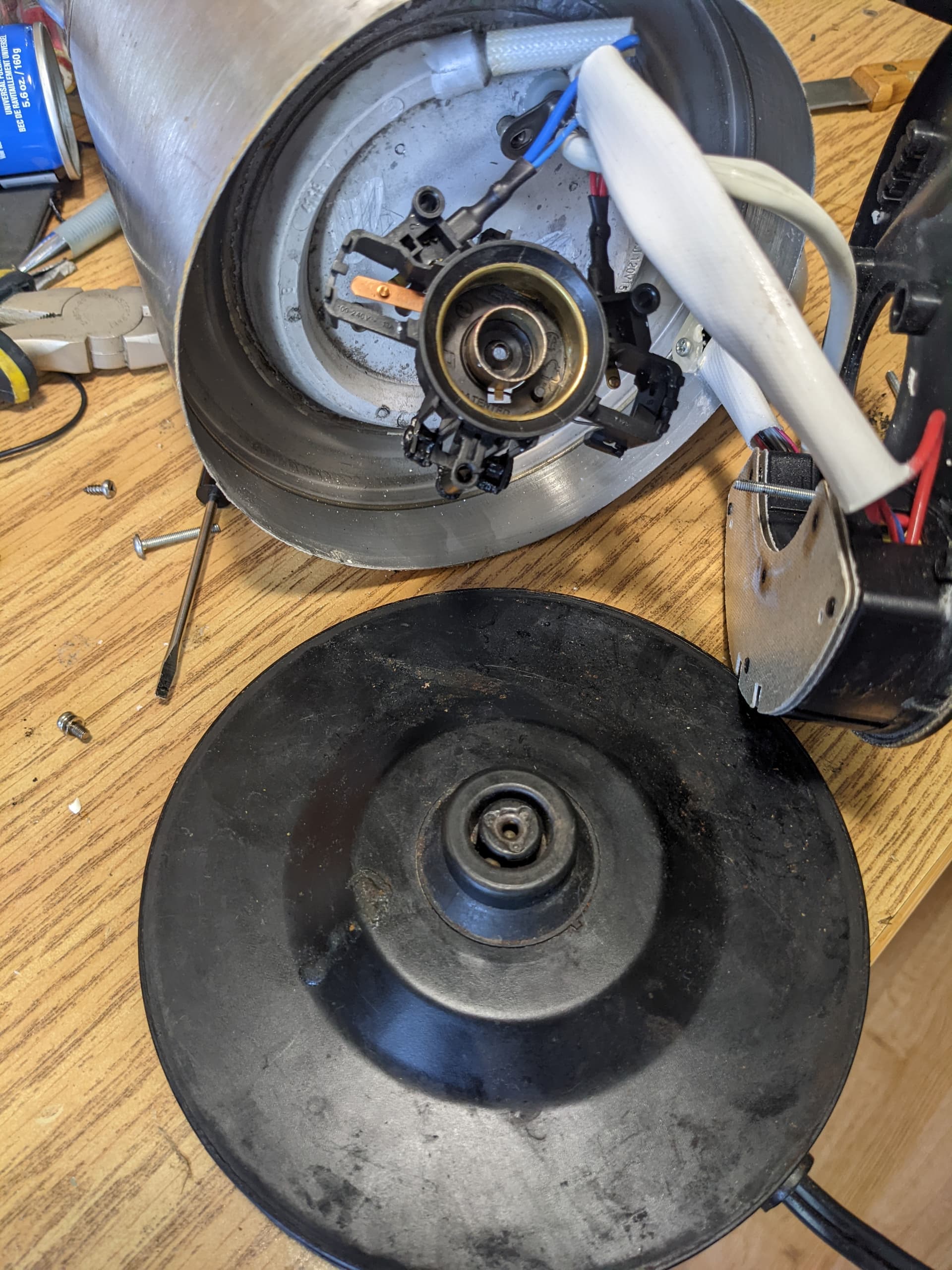
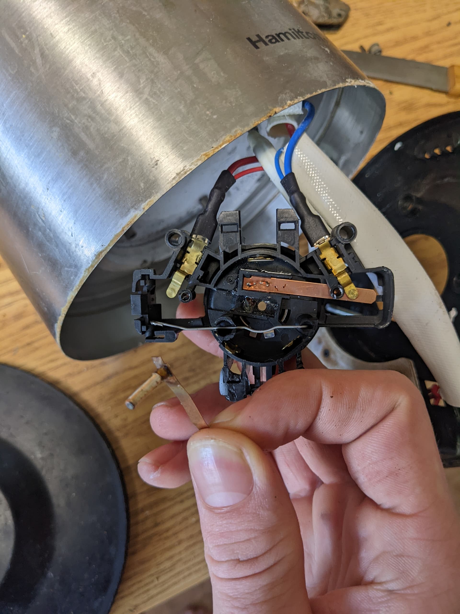
This was the initial set up but the piezo sensors kept breaking when attaching them directly to the underside of the drum, this direct vibration seems to crack the ceramic. They also kept falling off with just tape. A new solution is required.

Lessons learned:

  • LM317’s are only rated for about 1.5A out max
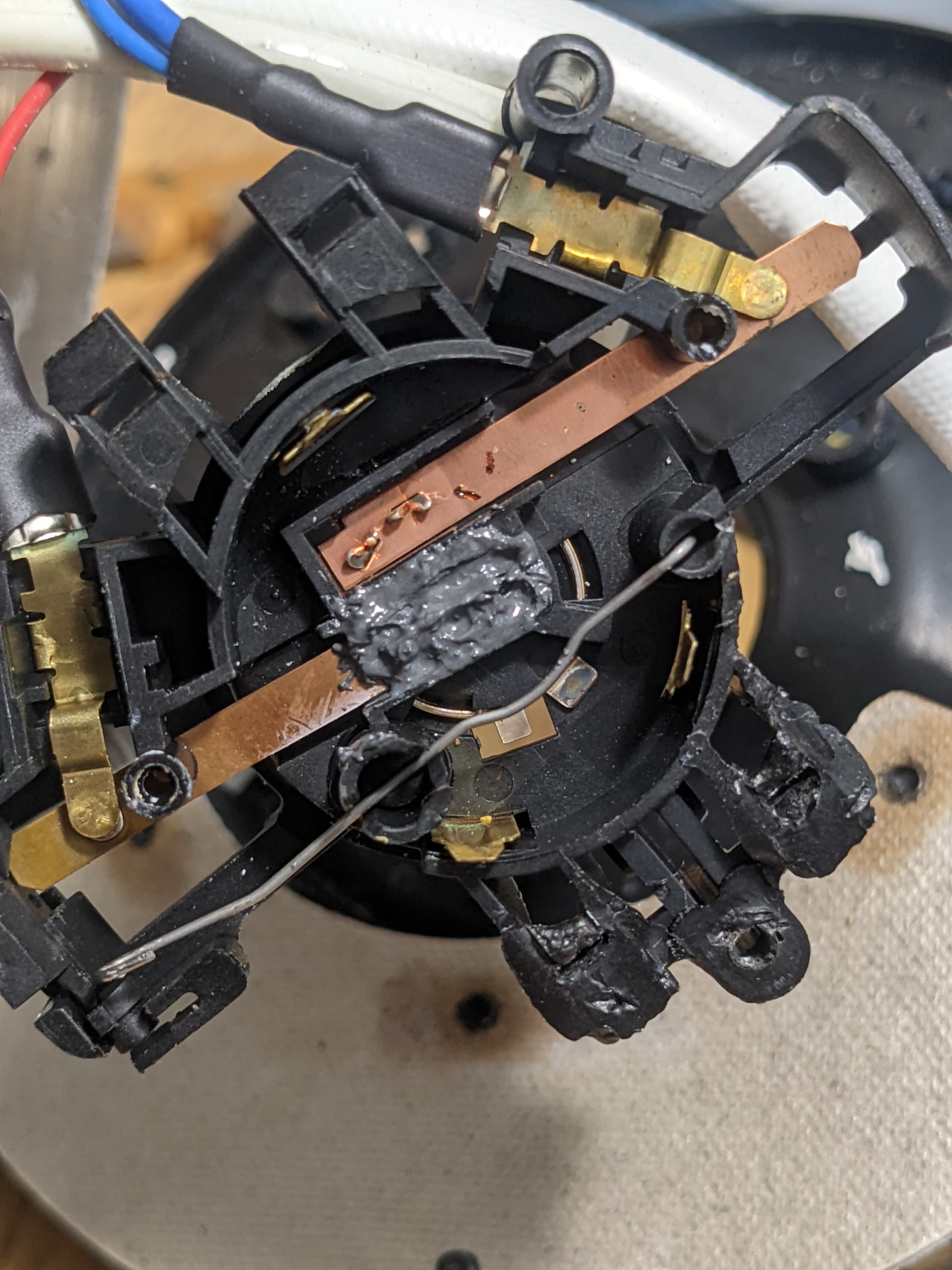
  • peizo sensors are brittle

So given that the piezo sensors attached directly to the head isn’t going to work, slight change of plans…

3 Likes

huh, my images seem to keep corrupting when i upload. test:

edit: converted to png. strange.

1.5A with sufficient cooling, yes.

They should also self-limit in both OC and OT scenarios, so you did something it did not like at all :thinking:

Well, my guess is that the PWM frequency of the WS2812s is faster than the current/thermal limiter can react to.

The average current it detected was probably too low to sufficienctly protect itself.

Why are you

IMG_20230614_104815

Like this?

Also I got banned from fedora forums for discussing about the insecurity of flatpak

:WHEEZE:

5 Likes

they incentivized me with cookies! it’s in the contract.

also this is pretty funny:
Screenshot_20230614_192209

3 Likes

I know when its @regulareel because he was royally clever enough to be regal

1 Like

well i had all strips on at max brightness and white which was trying to draw ~3.4A

I did have a heatsink on the LM317 but it still got very hot very fast

2 Likes

hmm, just noticed some potential overlap between some RGB stuff here and the OpenRGB stuff from the OpenPleb thread.

found this which coincidentally supports arduino and WS2812s. i wonder if i can leverage any of this. specifically the ability to design and select patterns and such. i dont want to write UI. and it needs to be simple enough for the drummer to modify on their own.

i was gonna use MIT but I’d be happy to license my stuff under GPL to be compatible.

1 Like

also this kettle failed again. ffs

1 Like

That’s 3 4 kettles in 2 1 years? How much tea are you consuming? making only 5 cups a day?

I think you need to recertify and remedially train the operator to impart much less impact force upon the tool during operation…

1 Like

Btw, the drum kit Looks really cool. Does it alter the noise
Sorry to mainly comment on the kettle

3 Likes