Why is that the case? Is it just that they did not enough space for 2DPC, and they just added as many slots as possible.
I would assume motherboard design starts with the requirements (what socket, VRM power, memory slots, PCIE slots and other IO), but why would the requirements be a weird number of memory slots.
I’m not quite sure what you mean with these examples unless I’m missing something…
According to the product name this is a Xeon E5-2680 v4 board. Both intel Ark as well as the data sheet on Ali say this is Quad channel. For 2 DIMMs per channel that’s 4 * 2 = 8, so it fits?
Both of these are Socket SP6 boards. SP6 supports (up to) 6 channels, with up to 2 DIMMs per channel, so 6 * 2 = 12 DIMMs at maximum. They both have less due to likely space and also requirement constraints, but regardless both 8 and 10 are still within the maximum count.
2 DIMMs per Channel usually results in higher throughput then a single DIMM, so it makes sense to not multiple the channel count, but instead the highest DIMM/channel count (i.e. 2).
On the flipside, if for whatever reason you were to go by channel count with a single DIMM per channel, these boards would fit 6 DIMMs each at maximum because there are only 6 channels.
I’ve wondered the same thing. I guess if you have old e.g. 16 GiB single rank DIMMs you could put them in the dual slots and combine with 32 GiB dual rank DIMMs in the single slots? Seems a bit niche though. ¯\_(ツ)_/¯
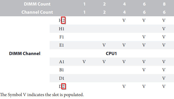
Oh right my bad, I was looking at the text in the second image, which counts to 8… when it’s not 8… that… makes sense. Anyway, same concept. The CPUs support 4 channels but using all 4 channels is not a requirement just like on the SP6 boards. So it uses 3 out of the 4 available channels.
On that note there are also consumer boards that only have 2 DIMM slots despite being dual channel and 2 DPC. These are usually targeted at overclockers (less components = less interference = potentially higher overclock).
I think there’s also a misunderstanding here? They are still supporting 2 DIMMs per channel, they just choose not to have all channels available. So in case of this board instead of having all 4 channels, they have only 3 of the 4 channels available, but still with 2 DIMMs each.
Given the same number of DIMMs you will get higher throughput if they are in separate channels. Multiple DIMMs on the same channel share bandwidth.
Who knows how that AliExpress “Cloud Star” board is configured, but the ASRock Rack boards definitely use all available channels from the CPUs, just that some channels have two slots while others have one. E.g. in the SIENAD10HM3 manual you can see that with 10 DIMMs you have 6 channels with four of them being 2 DPC and two being 1 DPC.
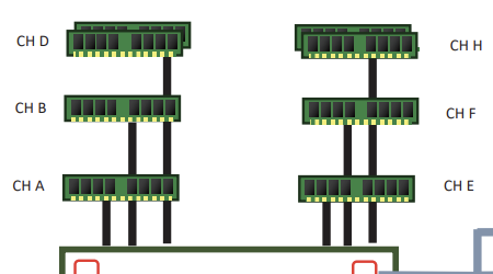
Agreed! The reason for the numbering is that electrically you want to populate the furthest slot on the bus first - you don’t want “loose pigtails” of traces beyond the termination on the DIMM since they cause reflections which smear the signals (and might even function as antennas radiating EMI). But to have that reflected in the slot numbering is a failure in user friendliness if anything is! Why not just call the furthest slot #1 and count up towards the CPU? Would have made a lot more sense for the vast majority of users, is my guess!
Exactly what I mean. I mean in this case these are server boards and it’s expected that SIs know what they’re doing with them, but it’s the same on consumer boards.