I’ve been working on automating the process of testing circuits for connectivity/functionality on some of my designs. My current process is as follows:
Secure PCB into test jig.
Manually flash test firmware, reboot and watch test jig lights come on to verify board was assembled correctly.
Re-flash board with production firmware.
Repeat.
I saw a video a while back about a fixture that incorporates another MCU to flash the board being tested and verify functionality with either a serial monitor or status LED to indicate a pass or fail. What’s had me hung up is I can’t figure out for the life of me how to flash an ARM chip with another ARM chip. Would there be an intermediary JTAG programmer? Can you bit-bang JTAG or SWD
functionality with something like a Teensy4.1 (600 MHz Cortex-M7)?
Well, it heavily depends on the implementation. For example, with the Pi Pico, I use the PicoProbe firmware (flashed to Pico A, to debug Pico B) and OpenOCD to do GDB debugging of another Pico.
I’d assume a modified PicoProbe firmware could be designed to automate the deployment and testing of firmware.
Not a particular helpful answer but:
It seems like you are trying to re-invent the wheel in developing a secondary arm board into a jtag programmer to test the primary arm board, why not just use a jtag programmer hooked up to the computer originating the code?
If you have a fancy ide you can even incorporate debug functionality into the programming of the mcu/board (via jtag) and get programming and verification done in one setup.
Now that you mention it, that might be a much more practical solution. Software to automate flashing and then just communicate with an external board to verify I/O connectivity and such. Might even be able to scan for available Bluetooth devices to confirm that it’s broadcasting.
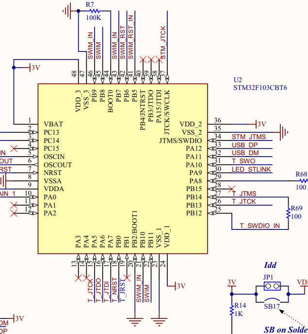
Absolutely can be bit-banged if you control the clock. Many ST STM32 evaluation boards have an built-in ST-LINK programmer interface, which is guess what - another STM32 MCU. Just pre-programmed with USB-SWD bridge firmware.
That’s cool, looks like the hardware side is straightforward enough. I think between that and existing implementations I might be able to pull this together.