Need some help here as there is no documentation online of this.
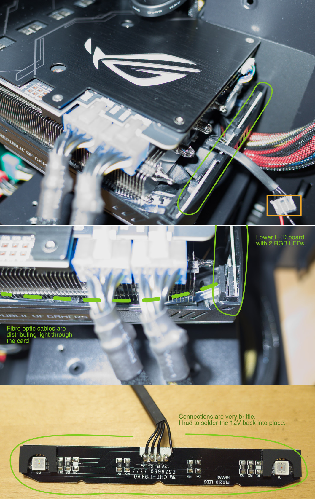
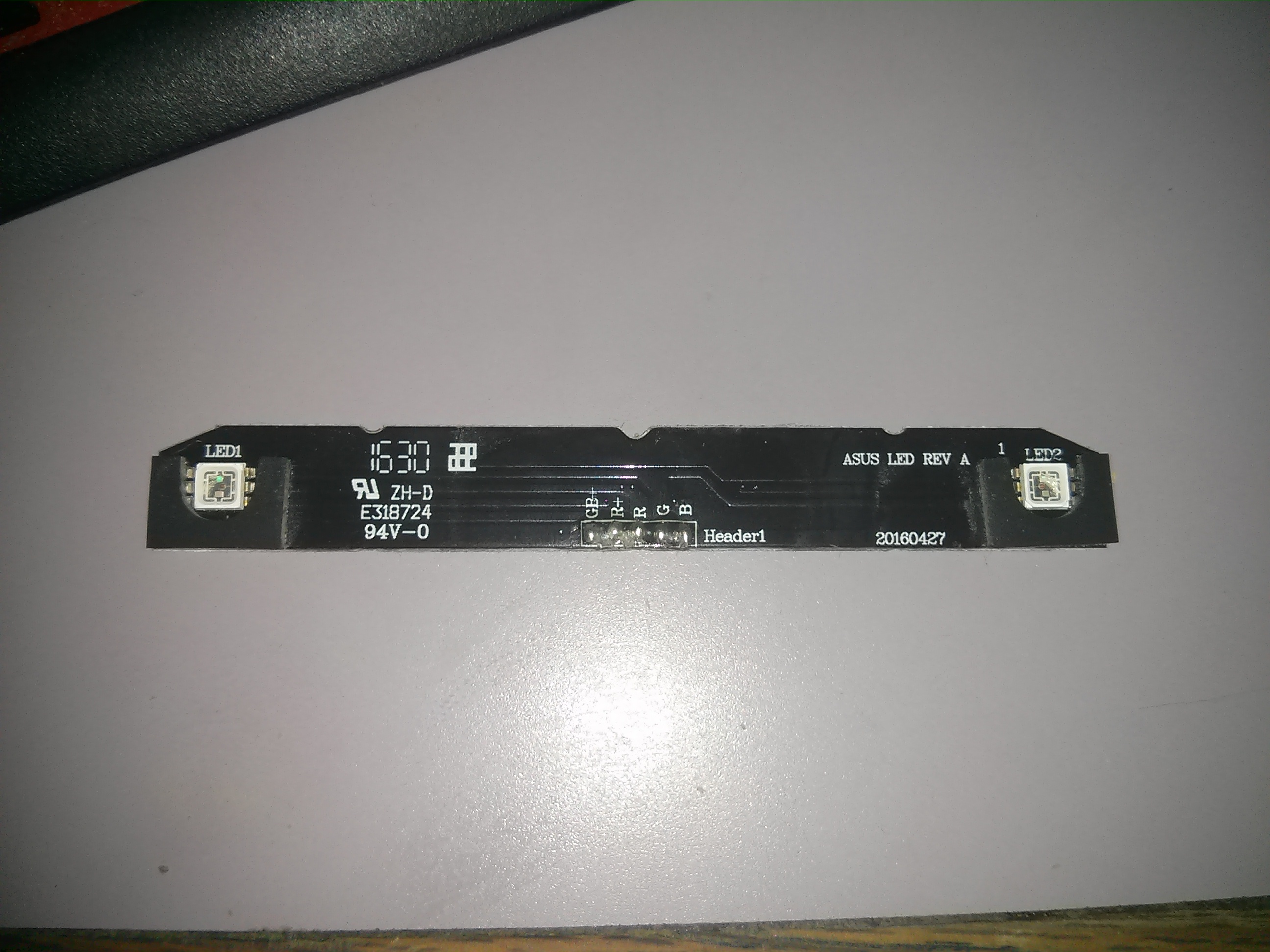
On the STRIX 1080 11Gbps I have, the fan shroud RGB leds use a 5 pin pinout to drive the LEDs, they’re labeled like this:
TOP
+GB
+R
R
G
B
BOTTOM
But there is no documentation on the side that goes into the PCB.
The wire managed to break off during maintenance and I do not want to solder it back on incorrectly so that it blows up the LEDs.
GPUs that also use this weird 5 pin layout include the STRIX RX 580, and STRIX GTX 1070 Ti. All RTX STRIX GPUs use 4 pins for the RGB on the fan shroud.
How do you measure with a multimeter which one is which? There’s no pre-existing data on what you should expect so without that info, people repairing old STRIX GPUs with this shroud could very well blow up their LEDs.
I would set it to (255,0,0) then run a voltage check for all, grounding out to the case. Repeat for (0,255,0) and (0,0,255)
I’m not an EE though, so someone else might have a better recommendation.
I’m assuming you’ve got a common ground in there and one lead for R, G, B, W. With that said, you’ll probably need to voltage test against (255,255,255) as well.
Not possible to control the RGB where I’m going that has soldering equipment. More likely what will happen is it will be left in a default state of breathing.
I’d pick up a multimeter from your local hardware store. They’re not super expensive and really helpful to have on hand. If you can do this in your PC, at your workstation, that’s the best solution
Oh, in regards to what you should expect, I’d expect either 3.3V or 5V when a line is on. It’s probably pulse width modulation.
For pin numbering, it’s with the notch side up, going left to right.
Also, it seems the +GB is a victim of a PCB trace lining directly up with the vertical part of the plus, wearing out the vertical line in the + making it look like -.
To anyone encountering this thread replacing their 5-pin LED shroud with a 4 pin one, do not fret. Get a 5 pin connector and only populate pins 1-4 going left to right, notch side up. The shroud will work exactly as intended because the shunts on the PCB for the 4 pin variant convert the 12V to 5V for you, so there is no need for a 5V rail.
Same goes if you want to use your card’s fan shroud RGB header if you lack a dedicated 4 pin 12V RGB one. Use a +12V from your PSU, then use pins 1-3 of your 5 pin to control the RGB PWM of your 12V RGB strip. This is how you get a STRIX 1080, STRIX RX 580 and STRIX 1070 TI to have RGB without the dedicated RGB header.