Because there isn't that great of a selection of usb sensor bars (at least in Germany), I wanted to built one by myself.
This is my first try doing something like this and wanted to ask for some advice to be on the safe side.
I want to use 4x Osram LD274 LEDs (datasheet: http://www.reichelt.de/index.html?&ACTION=7&LA=3&OPEN=0&INDEX=0&FILENAME=X100%252Fld_274-3.pdf) , and power it by USB (5V; 100mA ?)
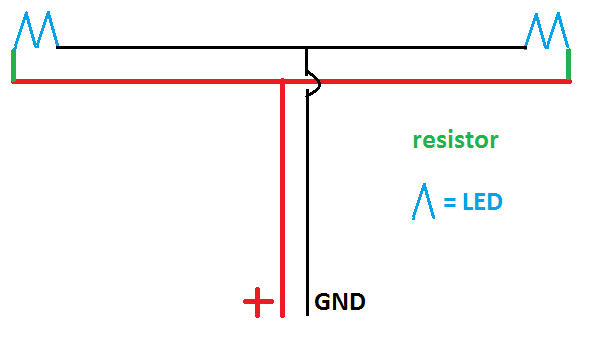
With this setting (see picture below) each "lane" would be at 50mA (?), and therefore I would need 46Ohm resistors, but there are only 43 and 47Ohm available, which of those should i get?
Did I forget something, or is this drawing completely wrong?
Help would be much appreciated, and sorry for possible grammar mistakes^^.
If you really want to do it from scratch, I'd say get a breadboard and try out both. Start with the stronger resistor and see if the LED has sufficient brightness to work. The components are all really cheap, so even if you do accidentally damage some then you should have more than enough spares on-hand to experiment with different configurations until you get a setup that works for you.
Another option is taking an existing sensor bar, cutting off the connector, and then putting the power and ground connectors into the appropriate pins on a USB connector. Sensor bars are obviously a little expensive first hand, but you can probably get a used one for cheaper than you would spend on parts, otherwise.
Those LEDs look like they handle up to 100mA each (I can't read German, but I can still spot specs in a datasheet), and a USB port should be able to supply up to 500mA in general. LEDs need resistors to limit the current they draw, and it is generally frowned upon to wire them in series. I would recommend getting four resistors spec'd to limit the current to 100mA at 5V and wiring all the LEDs in parallel, each with its own current limiting resistor.
V = I * R
V = 5V
I = 100mA = 0.1A
5V = 0.1A * R
5V / 0.1A = R
R = 50 ohms
So find four resistors as close to 50 ohms as you can get them, without going under (lower resistance = higher current). If you are worried the LEDs might be too bright or don't want to draw 400mA, get a few sets of higher valued resistors as well, and experiment a bit before you solder it all together.
Typically at school, using 5V supplies (ie USB) we connect the LEDs in parralel to each other, with a 220 Ohm resistor in series with each resistor. Then again, they say they're rated for 5V if I'm reading the datasheet correctly, so you might not even need that.
You should probably connect the LEDs in parallel though (I can give you a circuit diagram if you like, but you probably don't need it.)