Update
Getting all things done
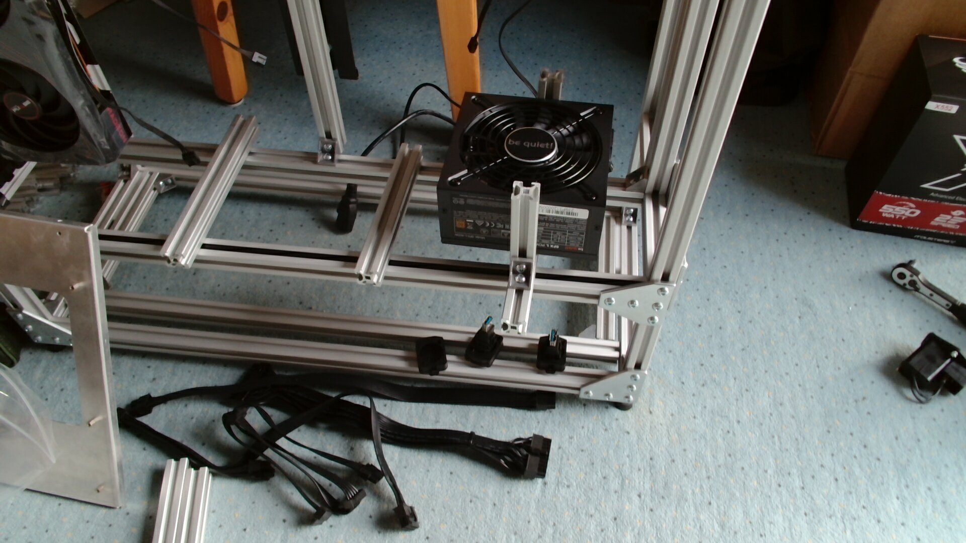
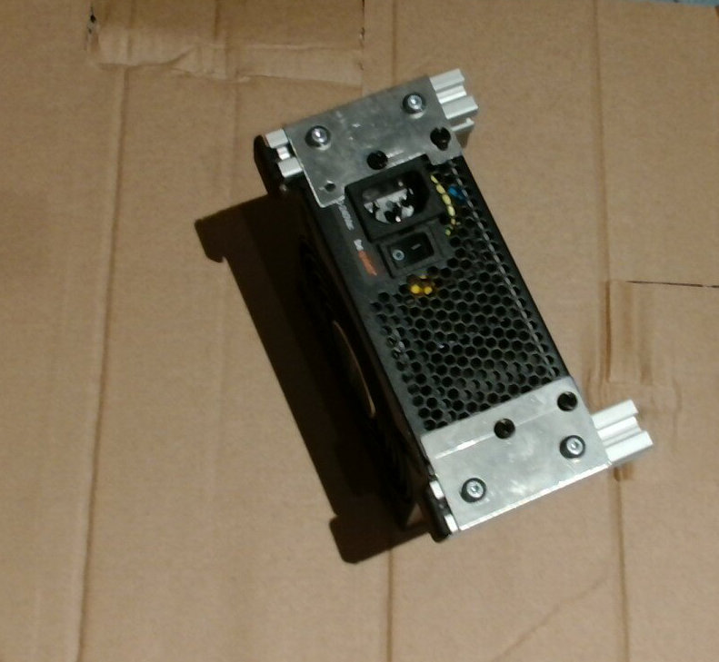
Last time (5 Days ago), I had prepared the PSU for installation. Now, comes ALL of the rest. Simple things are hard, hard things are almost impossible. Wednesday to Friday morning, when I needed the thing to be complete and ready to run for a lan-party.
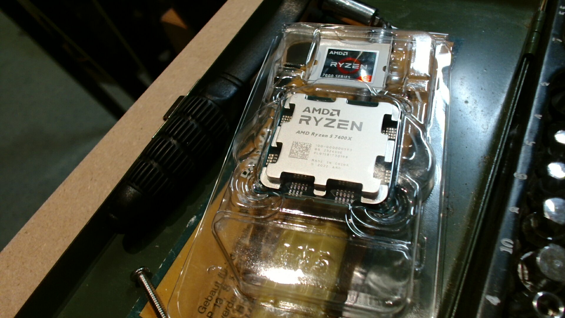
Let there be CPU:
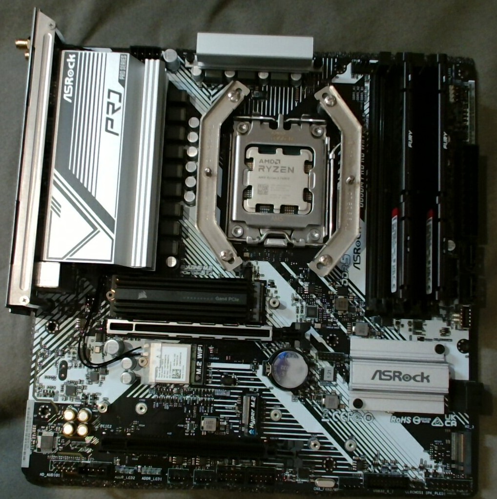
And CPU in mainboard (only had to undo the Cooler-Brackets once  ):
):
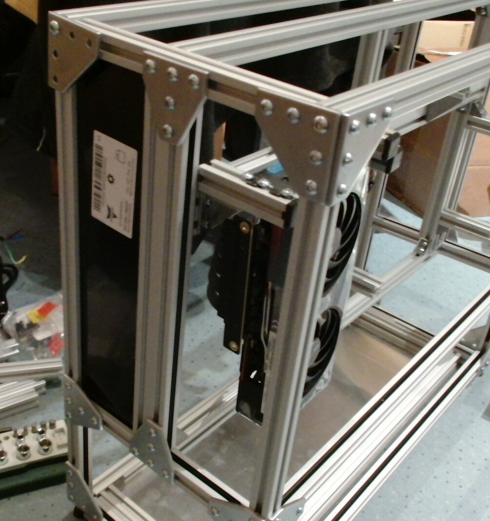
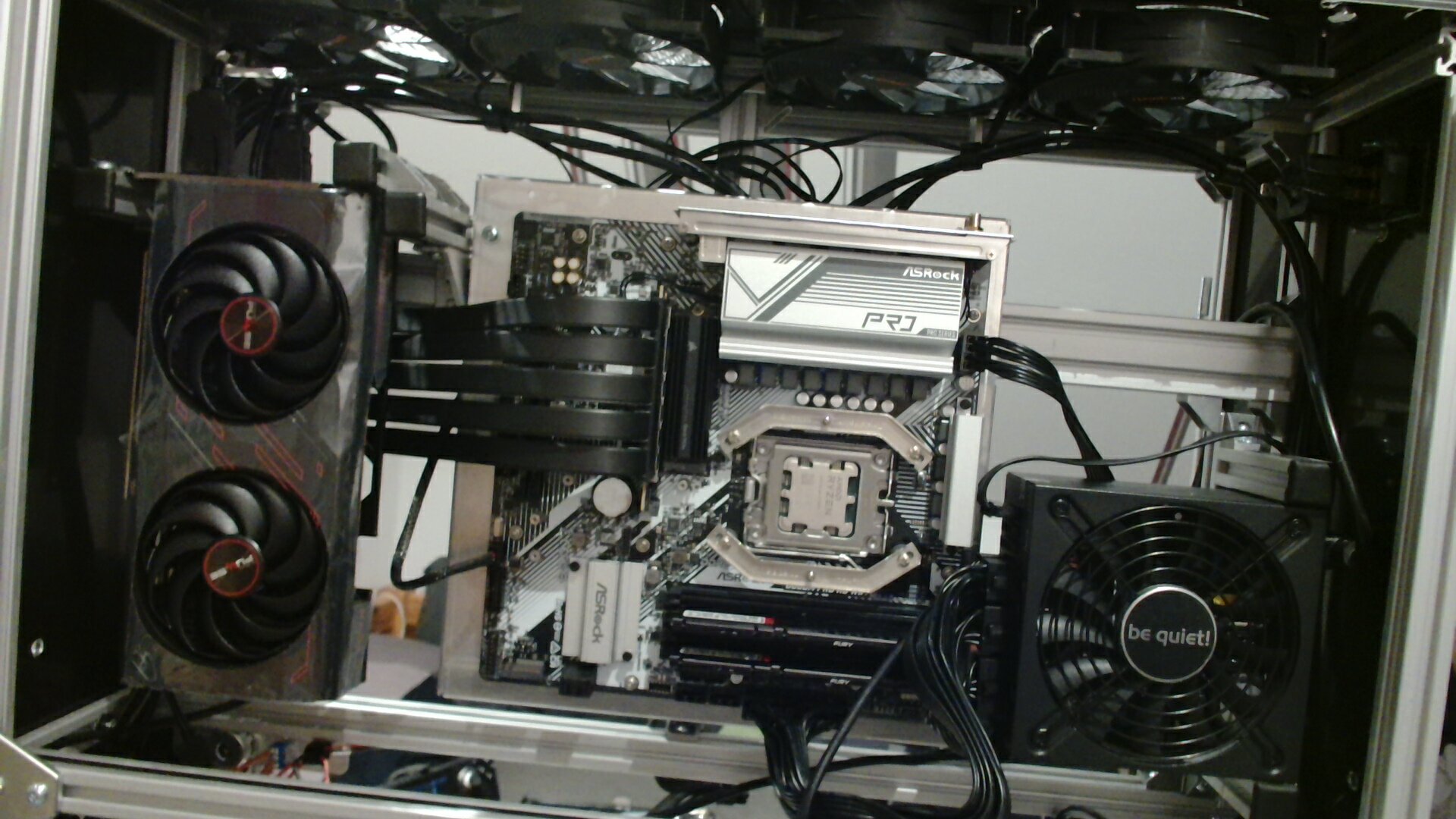
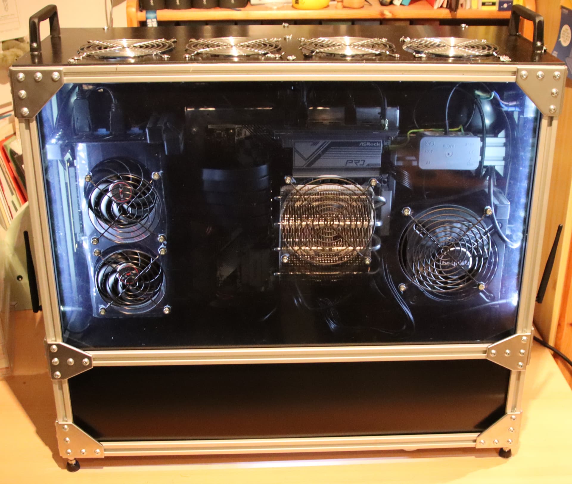
First time all computer parts being in the system:
Mainboard installed, all cables plugged in, cooler dry-fit, front plate in place.
…and, it is a snug fit, like, CPU cooler resting against plate snug, which, is not great.
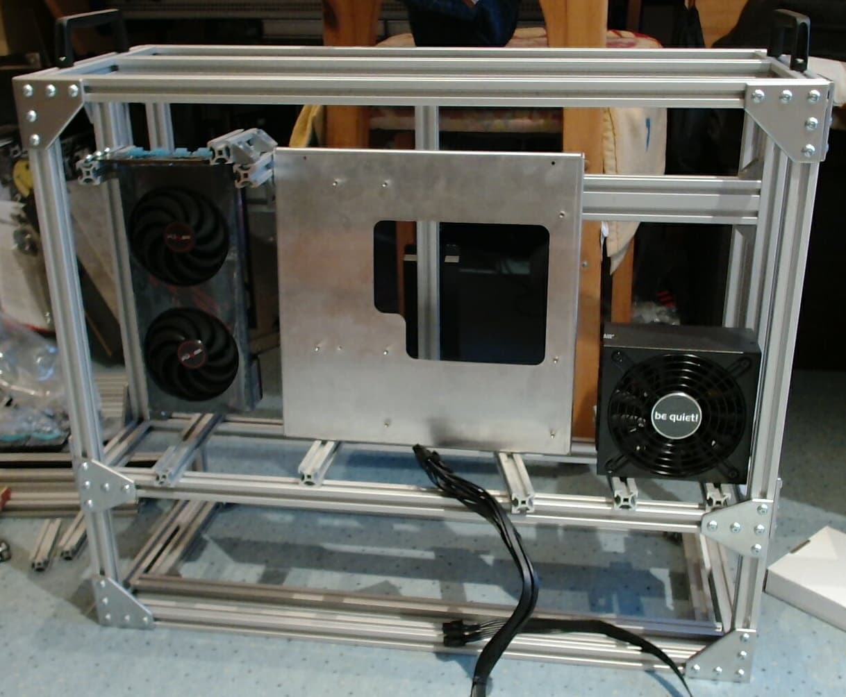
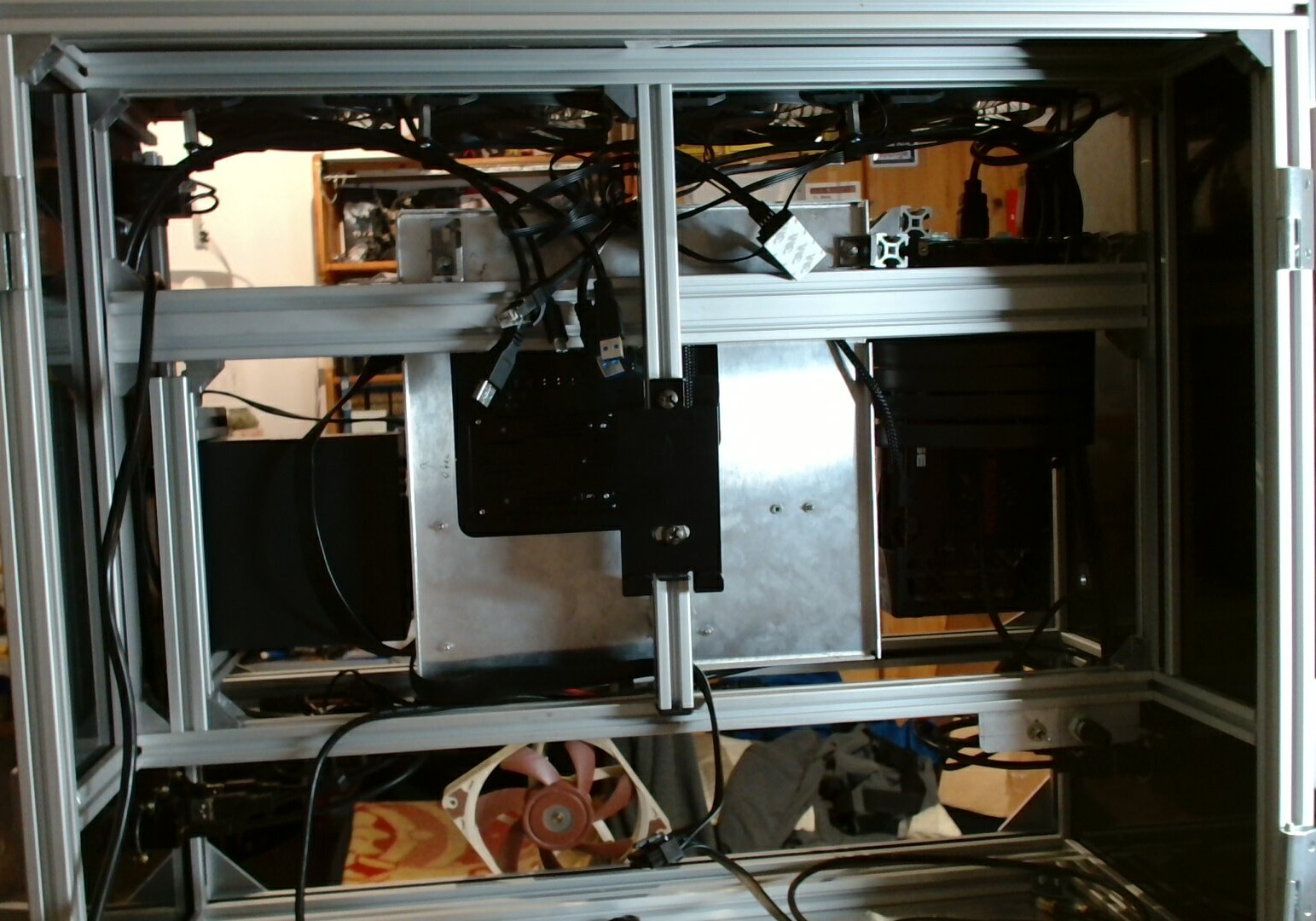
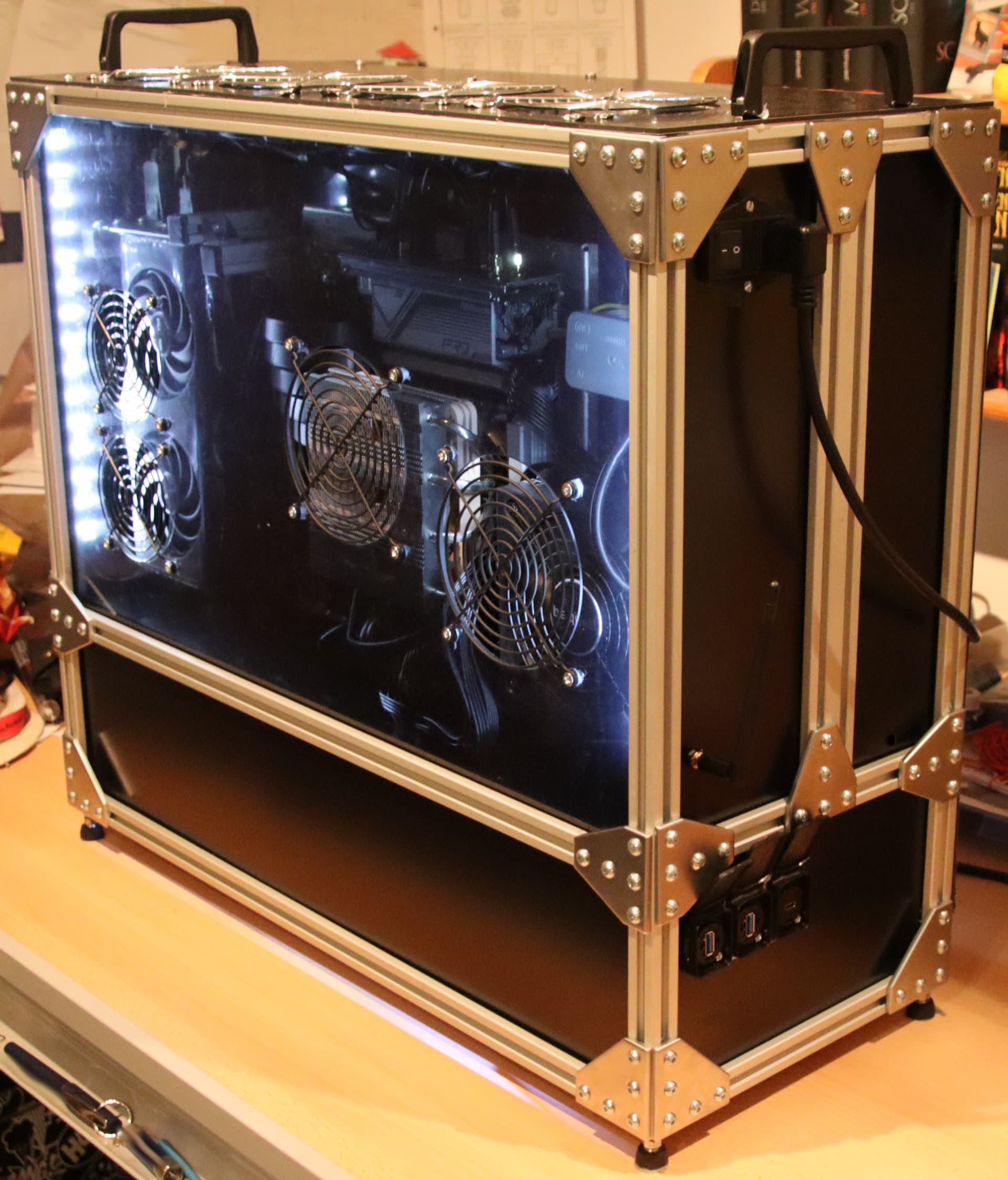
And the rear-view with none of the cables plugged in yet:
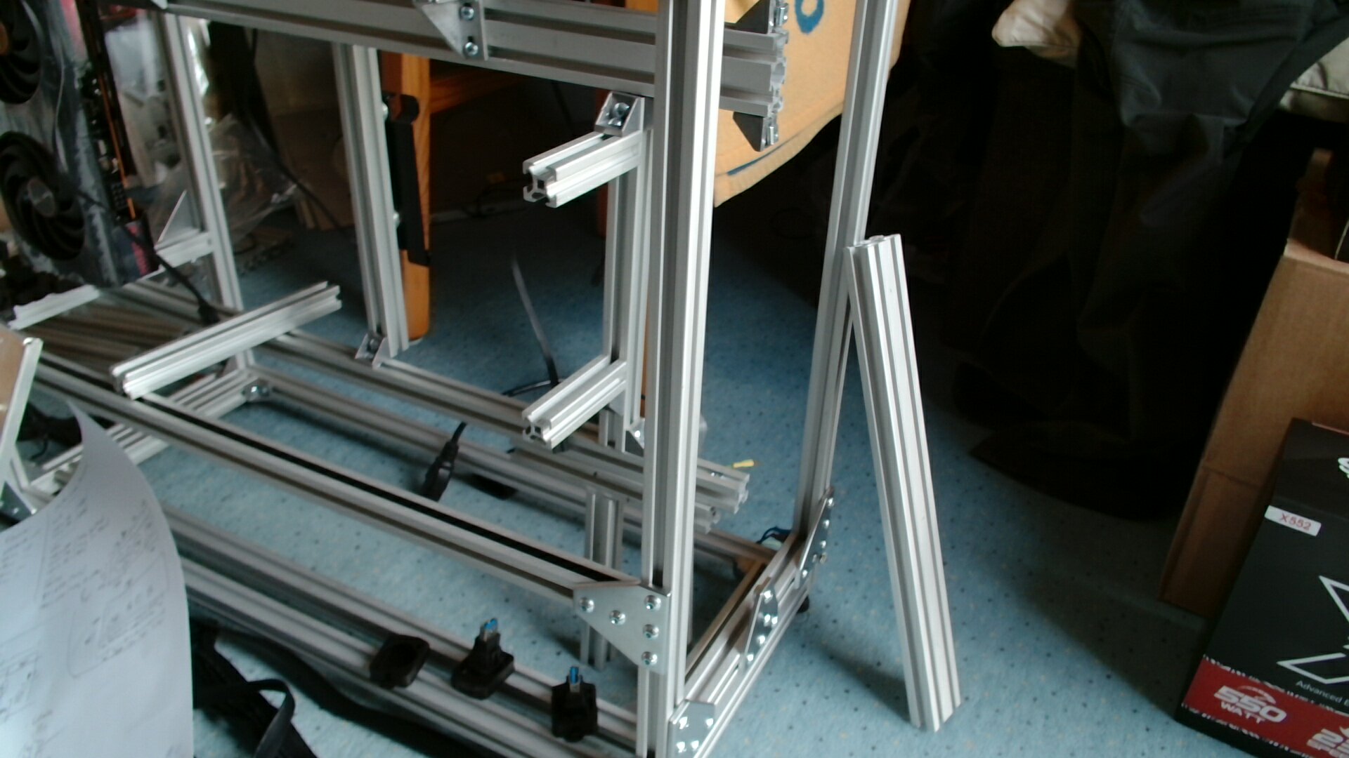
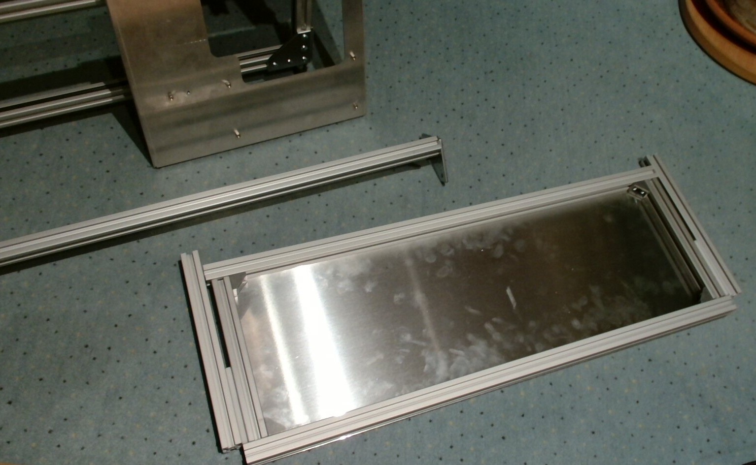
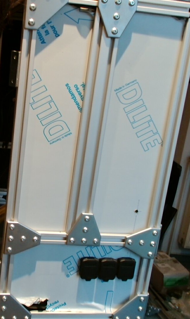
Midplate ready for assembly:
Assembly required sliding the freaking thing into place between computer and peripherals compartment, then fishing around in the dark for ten minutes trying to screw the headphone jack into place.
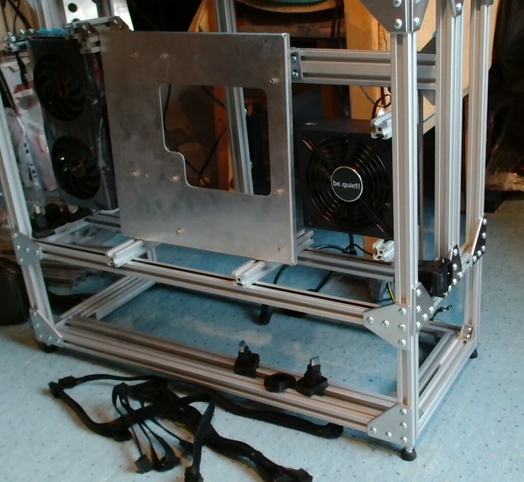
Lower side covers installed:
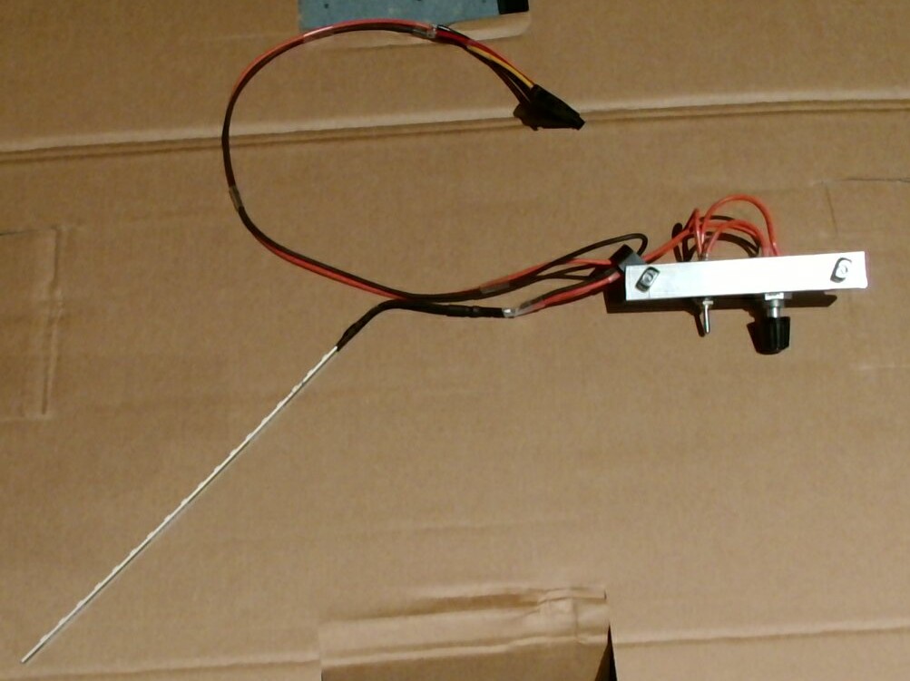
At this point, I just put the camera down and went for it for 3 hours. Had to think hard about cable routing since space is limited and I wanted a somewhat clean interior.
End of Wednesday progress
New day, more progress!
…none of which was documented, aside from this:
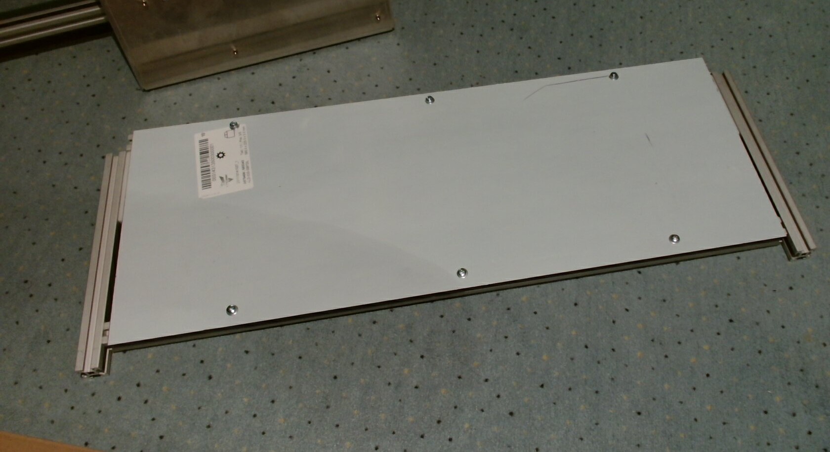
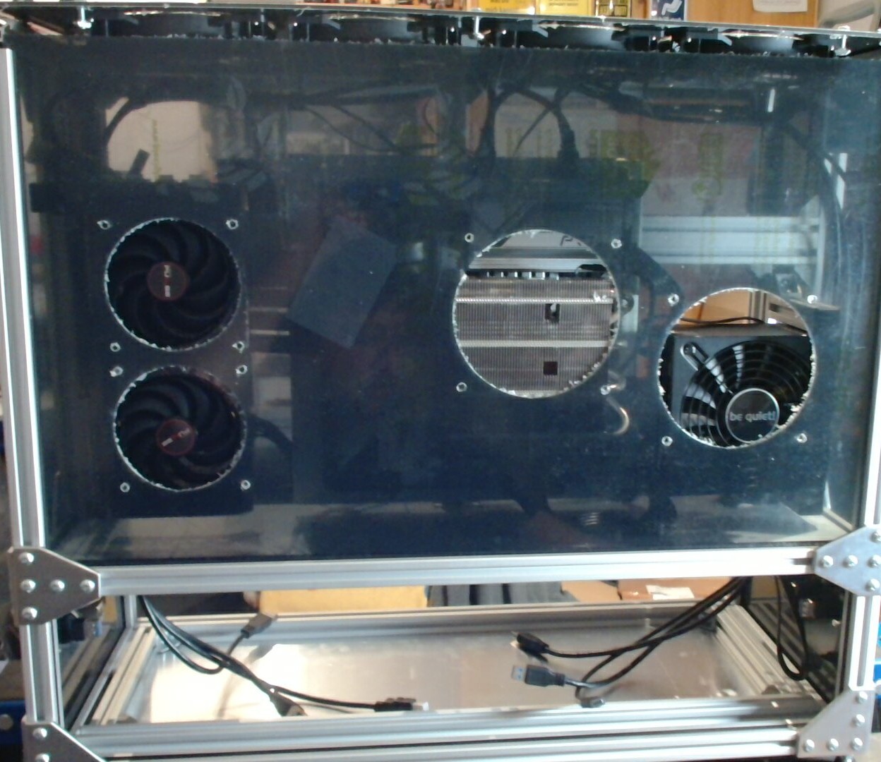
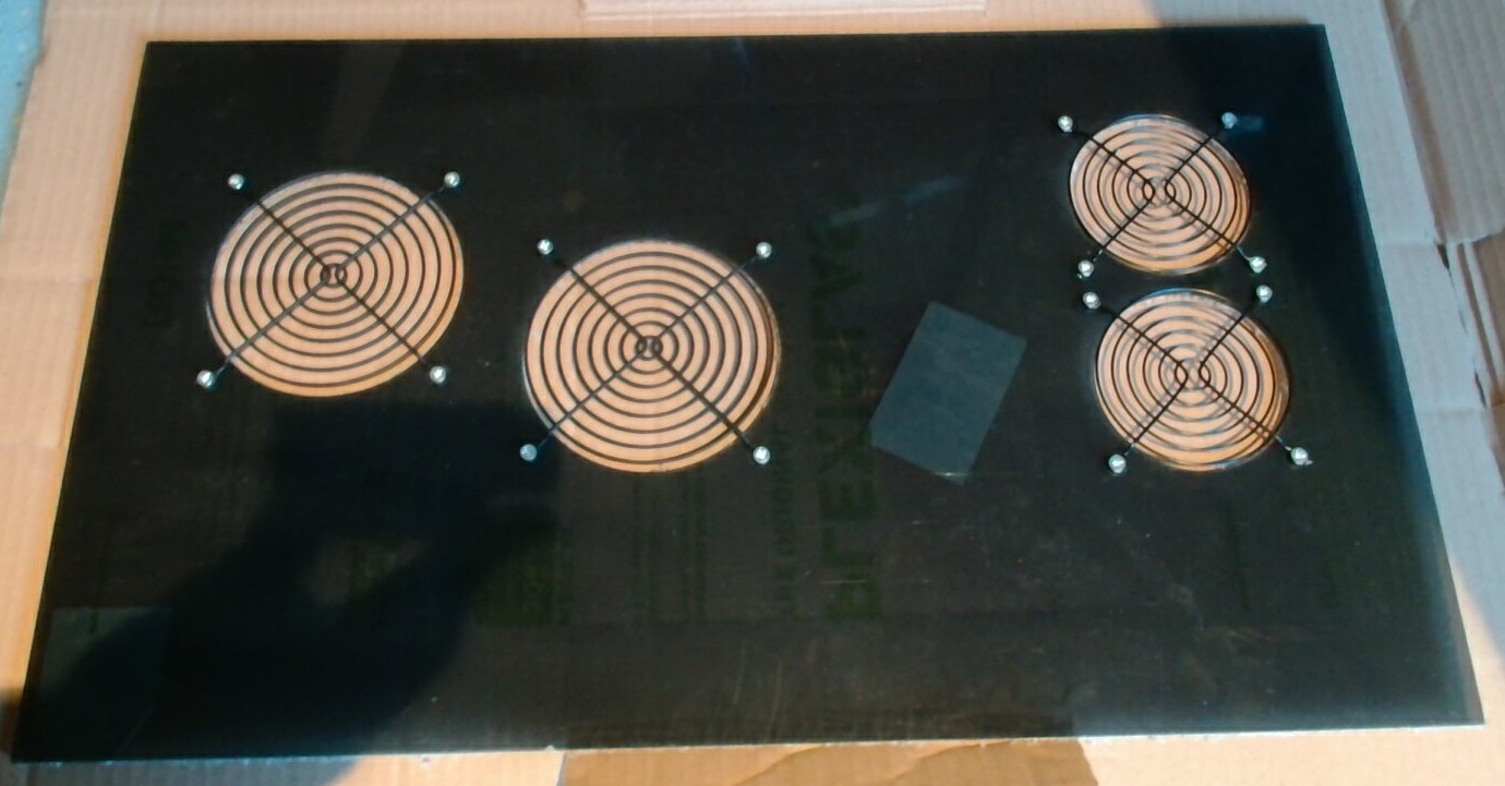
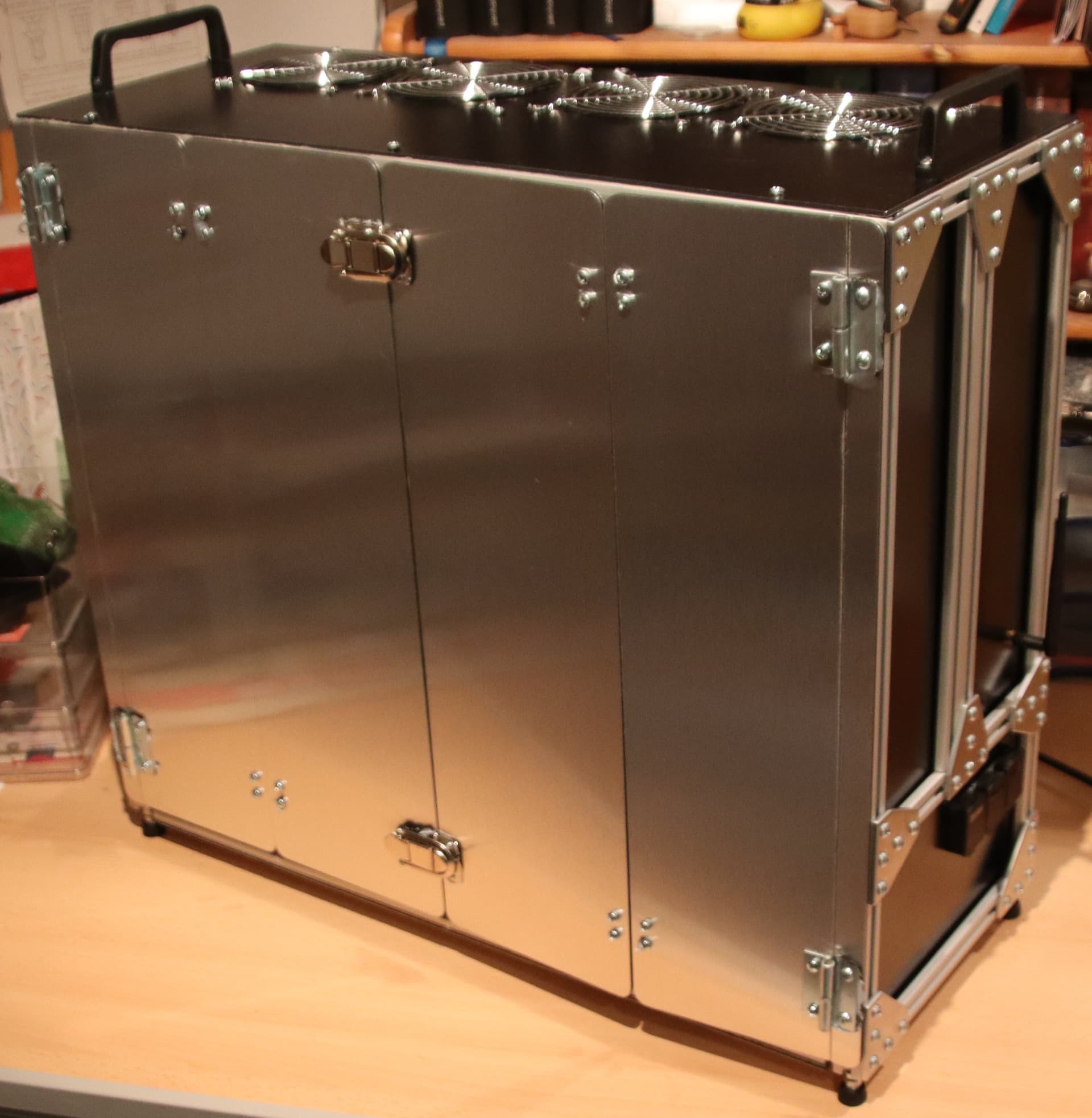
Front cover ready for installation:
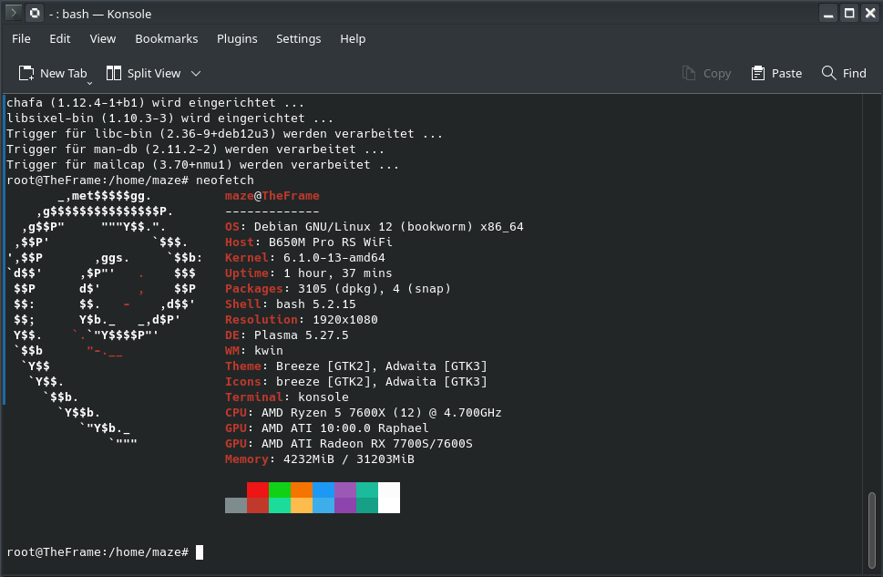
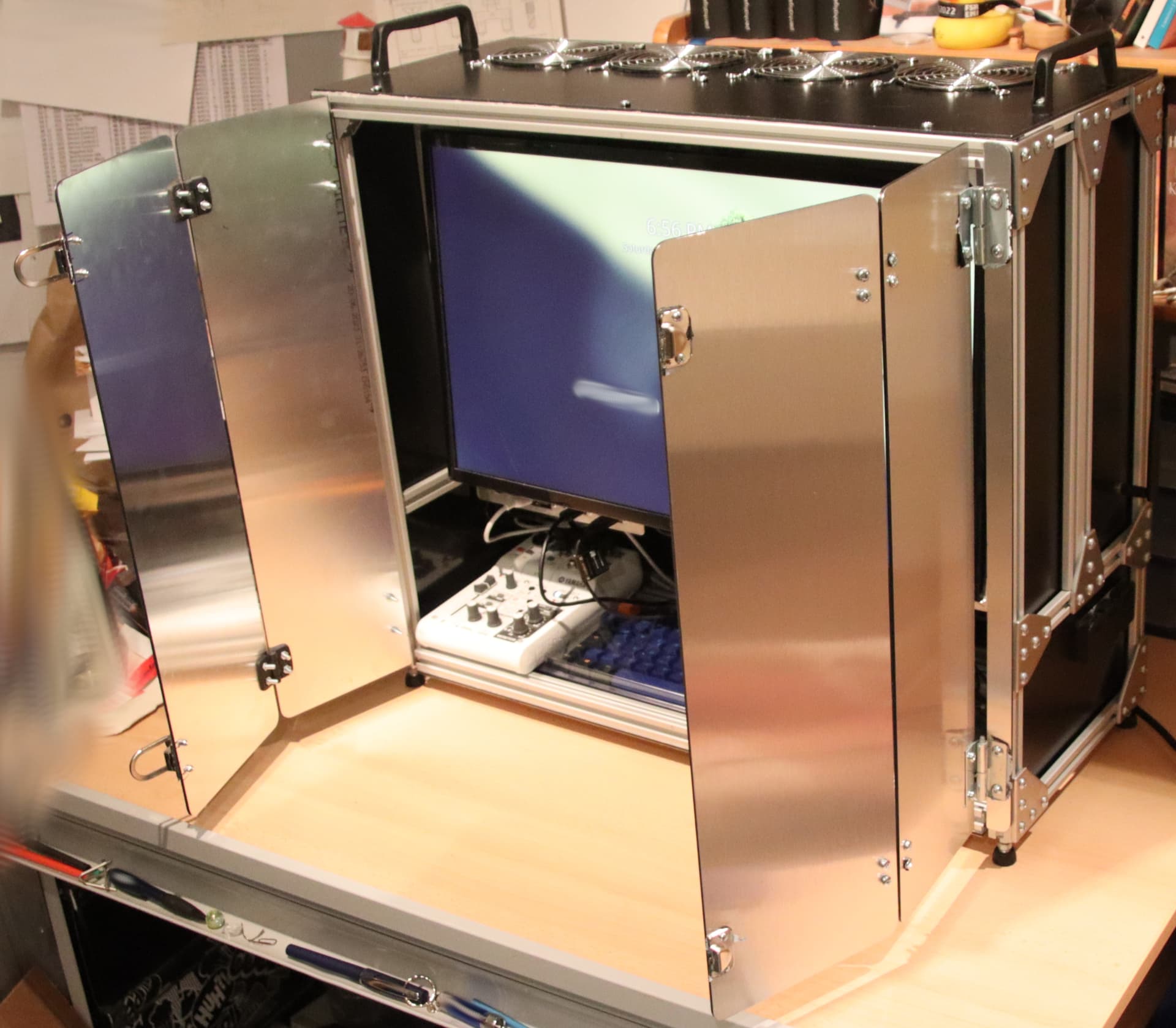
BIOS settings down, fan curves adjusted, OS installed:
Lots of strong language, lots of pinched fingers, more swearing, sawing, filing, test-fits, more pinched fingers…
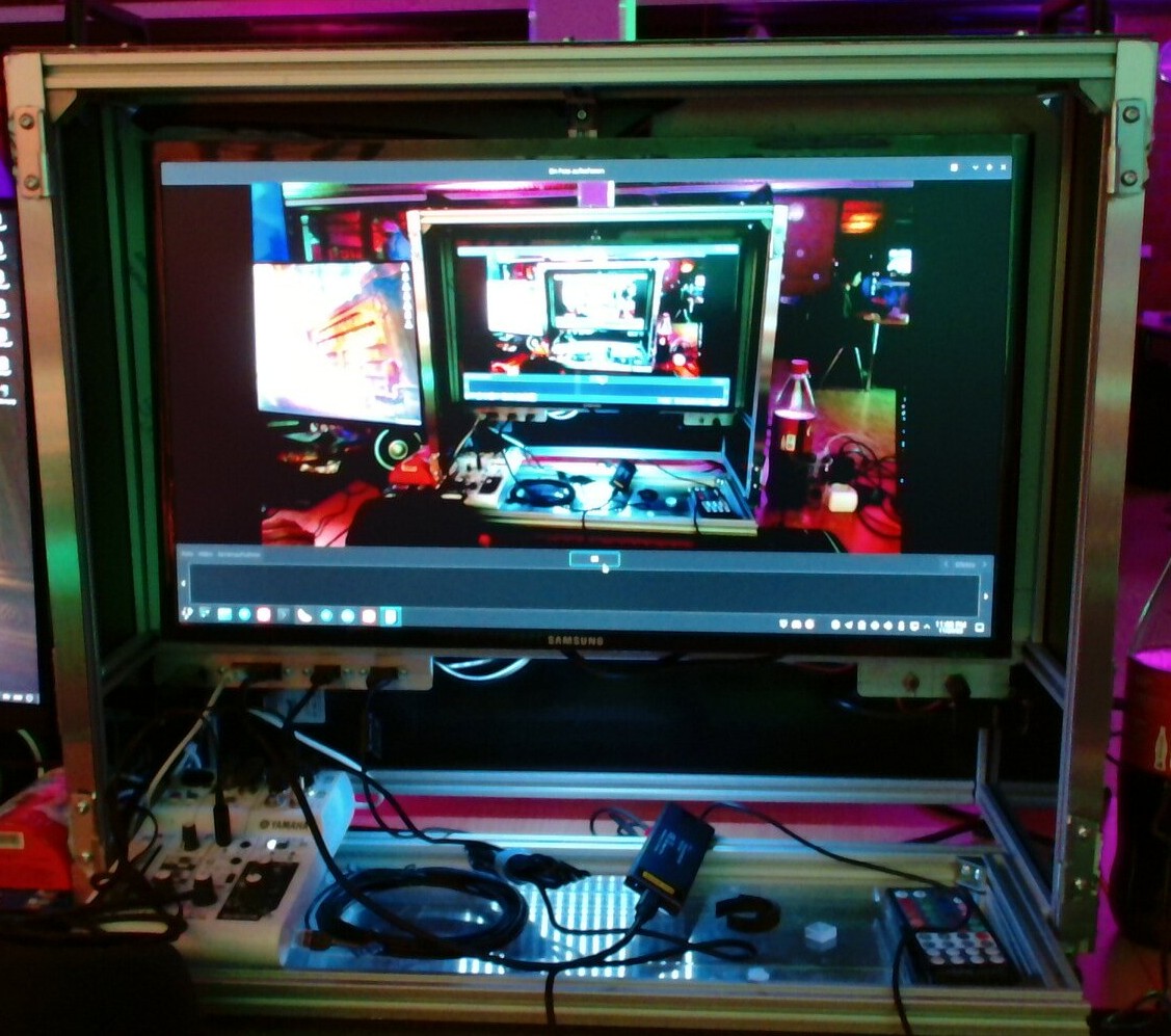
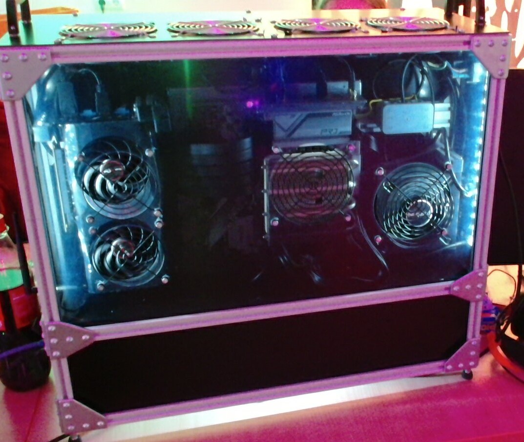
Poof!
Works, is quiet, is faster than the previous version.
Features:
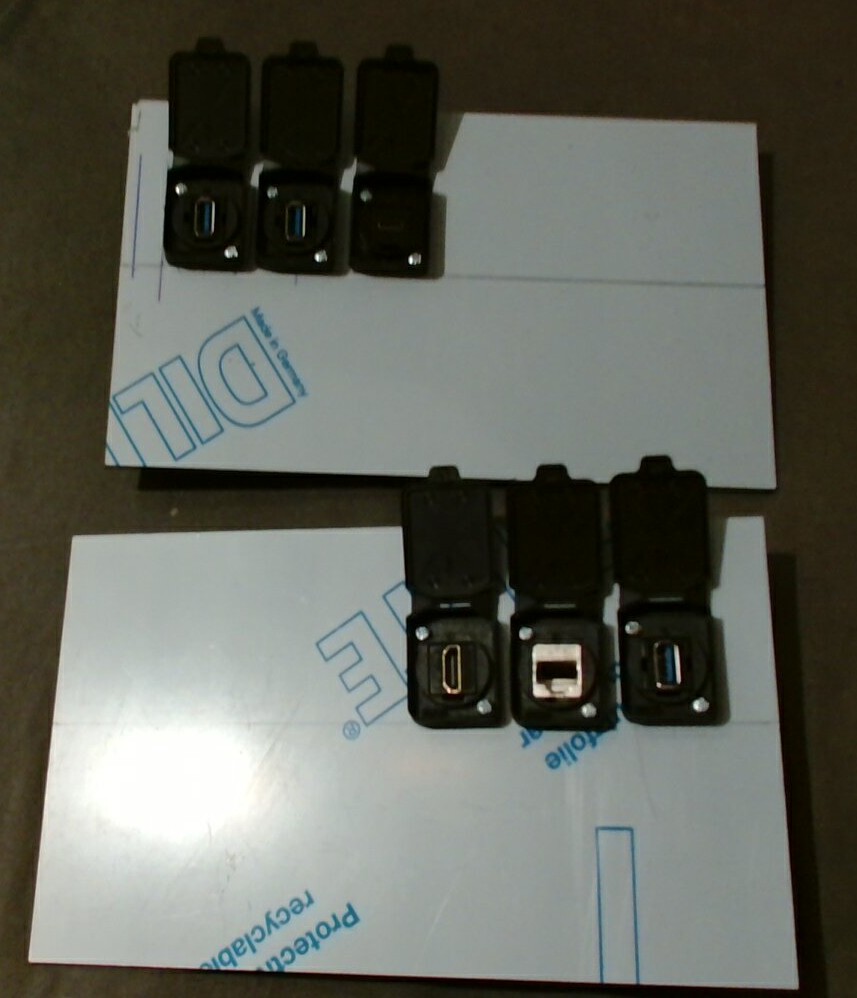
External Ports:
- 3x USB 3.2 Gen 1 ports
- 1x USB Type-C 3.2 Gen 2
- 1x HDMI
- 1x 2.5Gbit RJ45
Internal Ports:
- 1x USB Type-C 3.2 Gen 2
- 2x USB 2.0
- 2x USB 3.2 Gen 1
Yes, I am taking the  regarding the USB-Consortium’s naming scheme
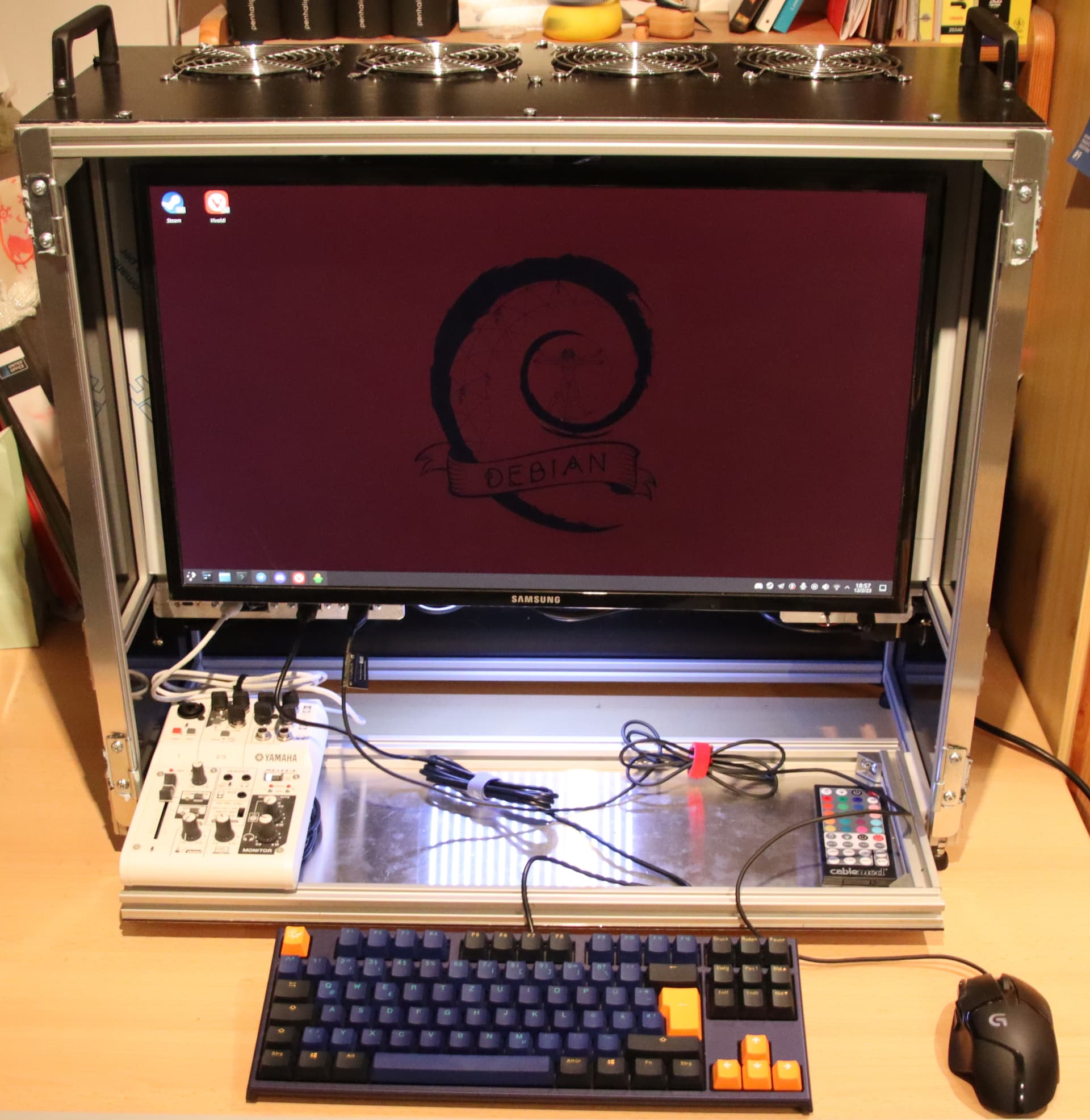
Miscellaneous:
- RGBW-Lighting
- dimmable white LED peripheral lighting
- peripherals drawer
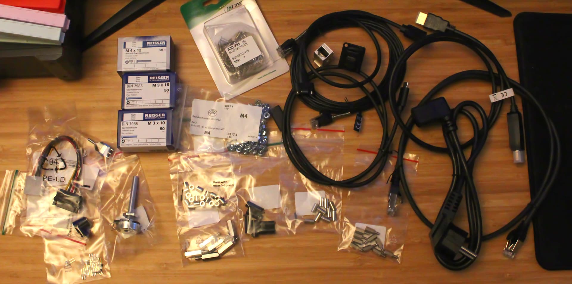
Total cost is TBD, all I can say is that 50 M4-type screws went into this thing.
One thing I know for sure, the gained compactness over Mk I had a price 
 . Unless something breaks, I am not going to touch this thing hardware wise ever again!