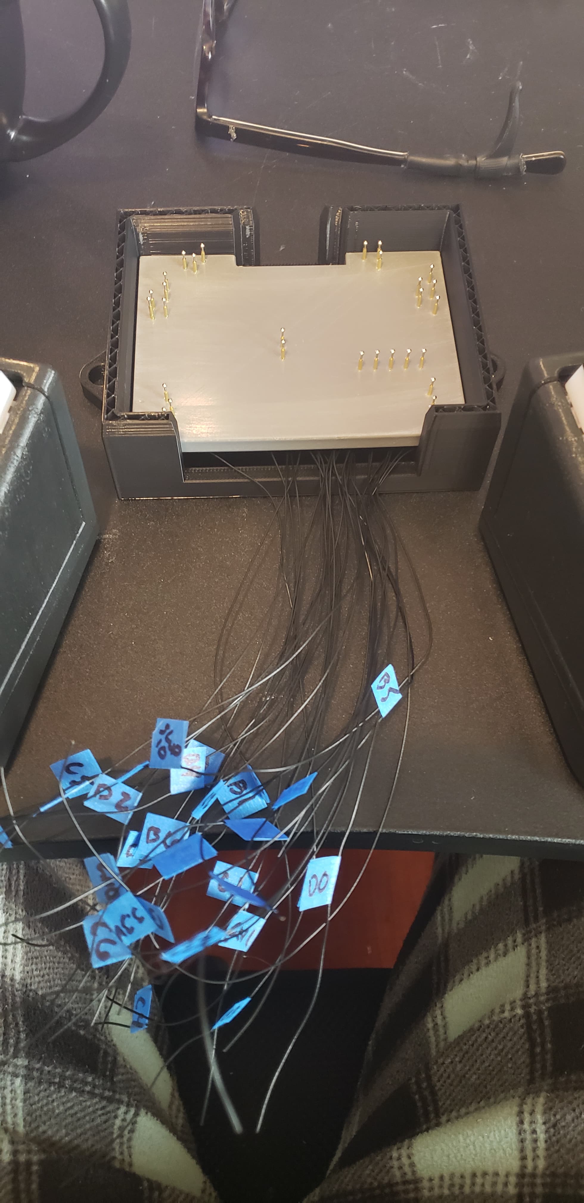
I’ve got a board (nrf52840 based) that I designed that utilizes a total of 22 GPIO pins plus programming headers. I’ve built a jig to electrically connect these pins to a raspberry pi pico.
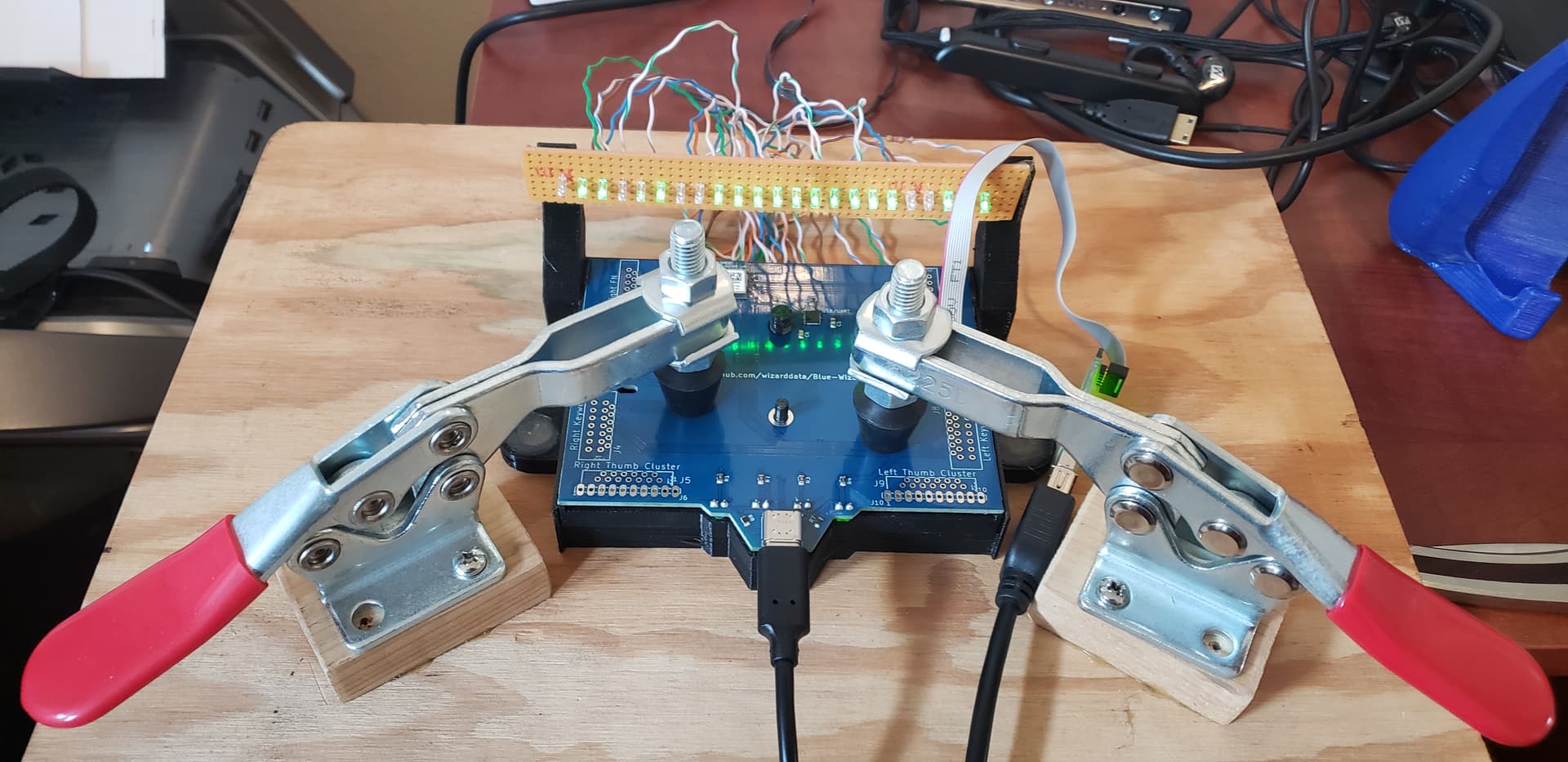
With a past revision of this board, I would connect the GPIO to a bank of LEDs and flash a test firmware that turned each LED on in order. Then I would watch with my eyes to see if any LEDS didn’t come on or if two or more turned on simultaneously. Programming was done over USB and JTAG to test both interfaces.
Past:
Present (unfinished):
That method sure did work, was simple, and provided plenty of feedback for troubleshooting. But it required a lot of very attentive staring. I’d like to simplify the process this time around by using an RGB LED to show a good or bad status for each board instead of watching a series of LEDs. Hopefully this will be faster as well. In theory the pico can program the board too by bit-banging JTAG, but that is going to come down to my programming skill (lol). The USB port would still need to be tested somehow as well.
I’m considering a couple options:
-
Serial connection between boards to request pins be pulled high in order. If serial communication isn’t established, or a pin doesn’t respond / multiple pins respond, then it’s a fail.
-
Send a ‘clock’ signal with one pin from the pico, and the 840 automatically cycles through it’s GPIO. Pico polls pins and counts unique signals / watches for shorts. When the count gets to the right number it’s a pass, otherwise it’s a fail.
How would you approach a situation like this?
Thanks!