So another gen with melting cable issues. It would seem like to me Nvidia want Molex to adjust the standard to meet higher loads or something. Kinda wild.
BTF 2.0+ for 1000W draw may just be needed.

tl;dw it seems like on der8auers 5090 the current carried by the 6 12V wires is very unevenly balanced causing 2 of the wires to get very hot. Suspicion that this happened in a more extreme way to the reddit user.
6 Likes
People really need to watch that video. Der8auer was seeing 90c temps a the GPU side and 150c temps at the PSU side… after 5 minutes!!  He stopped testing as to not damage his only 5090 and Corsair AX1600i power supply. He firmly believes his hardware would’ve melted in the same fashion as the redditor had he continued to let it run.
So NVIDIA’s 5090’s do not load balance across the six 12V pins. 3090 and 4000 series cards had varying levels of load balancing, but NVIDIA removed it with the 5090 generation. Der8auer measured that one of the cables was running 22 amps, I think he said the other was 11, while others ranged between 2-5 .
The PSU-side seems to be the more dangerous part of the connector now simply because it doesn’t have the GPU itself to act as a thermal heatsink anymore. But the lack of load balancing means adapter cables (the AX1200i only has PCIe connectors on the PSU side) are just as dangerous to use, as perfectly evidenced here.
4 Likes
Is that speculation or confirmed?
Yes, plus the PSU side has much less airflow in general.
It was confirmed, the 5090 FE doesn’t have the hardware to load balance the power pins. I think Der8auer even says it himself, but Buildzoid has discussed this before… in fact Buildzoid has a new video on this just posted but I’ve not watched it yet.
You’d have to buy the ASUS Astral to have power pin load balancing functionality. I am not sure if other ASUS models have it, or other brands as I decided in Jan to not buy a 5090 and quit paying attention on launch day to the models. Paying a $1070 upcharge to get basic safety features on a 1.1 safety margin power cable is precisely the power move I’d expect from a company as rich as NVIDIA, though.
3 Likes
Buildzoid did a great take on this as well:

6 Likes
+1. It’s not anything lots of haven’t been saying since 40 series launch, and that some folks were saying prior to PCIe 5.0 ratification, but Roman puts it all together nicely.
I’m not sure there’s anything in the specifications requiring 12VHPWR plugs or 12V-2x6 receptacles contain shorting bars for load equalization across pins. There’ve been a few teardowns finding plug shorting’s present but underbuilt for the redistributions needed. While Roman couldn’t do destructive investigation and the Moddiy plugs haven’t been x-rayed, I’d expect greater draws to increase chance of lateral failure within plugs.
Also, structural imbalances documented a year ago indicate 12+4 pulls margin from EPS, 24-pin, and mobo 8-pins (if present). If the return currents were balanced the 12+4 connectors’d run hotter.
Didn’t remember to mention yesterday but ASRock Phantom Gaming and Taichi PSUs include 12V-2x6 specific OTP. Not a thermal fuse but it’s supposed to do the same thing. On the PSU end, anyways.
Not sure if there’s other PSUs implementing similar OTP.
I think it’s the other way around. Since there apparently is a shorting bar on both ends, there is no mechanism load-balancing the current between individual wires (if there was e.g. a current sensing resistor on each wire, a voltage drop across it should encourage more equal current distribution.
What I don’t understand is why doesn’t the PTC nature of copper increase the resistance enough to facilitate more equal current distribution. The coefficient is about 0.4%/K, so my gut feeling is that the relative resistance between individual cables/links is above the typical 5% tolerance. It’s also possible that ripple currents are at play, preferring paths of least inductance.
the problem is all about the contact on 1 of the 2 sides of the connector. With a high resistance on the connection pin, that decreases the current through that wire, causing it to go to other wires that do have good contact.
GN Steve demonstrated this even back with his 4090 12VHPWR connector videos. Even the NVIDIA adapters can have poor pin contact, this is explicitly why users are not allowed to bend the NVIDIA adapters within several inches of the connector as to not cause the pins to misalign.
Also just to point it out, Der8auer was using the official Corsair 12V-2x6 adapter with his AX1200i testing that saw temps of 150c. So if Corsair didn’t get it right then almost none of the other PSU made cables are going to be safe either. But the 12V-2x6 standard itself is inherently unsafe regardless, in my opinion.
1 Like
Even the official Corsair one doesn’t seem to be to spec in the video. But I totally agree the connector is inherently unsafe.
Same. So far as Corsair goes, jonnyGURU refers to it as a zero margin connector. Not supporting it’s not a business option so that’s probably as close as anybody’ll get to saying it’s not possible to get 12+4 right. Only takes path imbalances of a few tens of mΩ to produce the amperage spread Roman measured.
While I don’t disagree that this connect didn’t meet the 12VHPrw specs, I completely disagree with the premise that this was even close to the root cause.
If it was a pin connection issue that he proposes, logically all the cables would generate a similar amount of heat from poorly designed contact and all third party cables would be failing.
We can clearly see that way too many watts passed through a single cable, supporting to Buildzoid argument. He can argue that the improperly spec’ed connectors contributed but IMHO, a majority of the blame lies with Nvidia, not the cable. Even with a properly spec’ed terminal, that much power through one cable would still melt it.
Here is the thing though, too much power going into 1 cable is the result and not the cause.
In the GPU all cables are connected to 1 trace, so the GPau can’t ‘ask’ for more power on one cable.
I’m going to guess that this is the same for the power supply side, where they all connect to one rail( but this is to be confirmed)
The current will go through the path of least resistance, so not all into one or 2 cables. The only way it will do that is if the resistance is lower for that path into 1 or 2 cables.
So that leaves the following options:
- the cable itself being broken / thinner at some places.
- multiple pin and socket connections having worse contact.
The design with no margin is the cause in general with how small these pins in the GPU are, it’s very difficult to guarantee a proper connection. But I’m curious to what each individual case differences.
I personally prefer to call it the path of equal voltage. Path of least resistance implies that if any single wire is moderately less resistant, all the current should go through it, which is not the case. Path of equal voltage means that the current flows in such a way that at each junction all incoming/outgoing voltages are equal.
Thinking
To get the actual current distribution between the wires we need to follow Ohm’s law (V=IR) given individual resistances Ri and combined resistance 1/R = sum(1/R_i).
In a simplified case of R1=1mΩ, R2=2mΩ, we get 1/R = 1 + 1/2 = 3/2 => R = 2/3mΩ.
So for I = 30A => V = 30*2/3 = 20mV => I1 = 20/1 = 20A, I2 = 20/2 = 10A
Meaning ignoring the other cables, Roman saw at least twice the resistance between the two hottest cables.
I do believe there are also options beside cable, like uneven resistance on the side of the GPU or the PSU. In the end, even if you connect everything to a bus bar, that bus bar itself has a resistance, and PCB layers are rather thin. Plus, given the weird position/angle of the connector at 5090 I wouldn’t be surprised if there was a resistance mismatch between the wires.
Still, more current will go through the path of least resistance, like you said. Meaning there is yet another option; all the wires are up-to-spec, but one or two are even better than spec – got better contact, slightly less inductance, w/e, the machine crimped it a bit tighter.
Does that make the cable out-of-spec?
I don’t have access to PCI-SIG spec and I don’t know if they specify the maximum variance between individual links’ resistance; but if they don’t, good luck everybody.
Anyone wanna invest in a XT60 conversion kit? 
I did post a link to the spec in this thread. What the spec says not more than 50% LLCR variation on each of the groups. and those groups are just the 12v and ground. So not more than 50% LLCR on each. and LLCR is 6mohm.
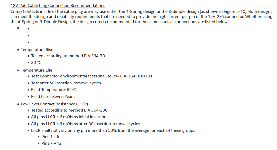
6 milliohm is obviously not enough to get 22A over a single cable as derbauers video. letting ai do the math:
There was some wrong Ai stuff here, It’s still morning but maybe i’ll calculate it when i had coffee.
Your AI is wrong as it assumes all 575 watts are dissipated at the cables!
See R_avg = V/Iavg.
You are right, I should not be doing these things right in the morning. I edited my post.
The ratio is correct then? So the resistance on the path of the 5 other cables is about 5 times higher than the path of the 1 cable getting all the resistance.
the LLCR variation says no more than 50% variation. so 50% higher, each cable has a connector on each side. so inside the spec 1 cable can be 2.25 times lower. But that is assuming resistance in the cable is negligible.