Hello electrical engineers, techs, or anyone else with similar knowledge. I need some help with figuring out what type and kind of (in-line) resistor(s) to use on a 24v (1.53w) 40x20mm computer fan to drop the voltage by 10-15% down to around 20-21v.
I’m all set with soldering, but have no clue where to start with figuring out the above, so any guidance would be very much appreciated. Thanks all.
Im not great at the math with these things, rarely do them, but I believe you would want a 1/4 watt 47 ohm resistor. You may want to upsize to a 1/2 watt just because it is probably only a few pennies more and gives you more heatsinking capability for the waste heat.
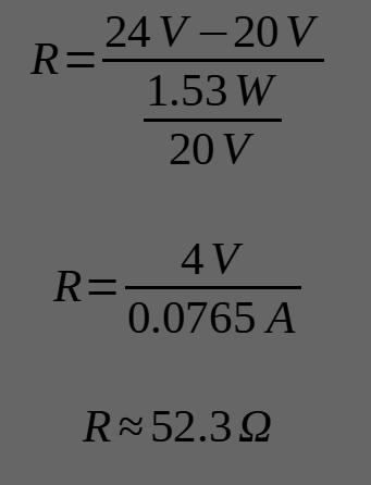
You have 24v, you want 21v, so that means your dropping voltage is 3v. You said your wattage is 1.53w, which means 1.53w/24v = 0.06375 amps. So you should be able to take the 3v drop you want, divided by 0.06375a and you get a value of 47.05. So that is the ohm value you are looking for. Rounded to the nearest whole ohm and commonly available size, 47.
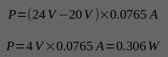
For wattage on the resistor, the resistor will be absorbing 3v of power and turn it into heat. So I just took the total wattage, divided it into 24 parts (which the result is actually the amperage rating), and then multiplied it by 3 parts (the 3v being dropped) and got .191w the resistor will turn to heat, which you round up to the nearest resistor wattage rating. Common ratings are 1/4, 1/2 and 1w. You could always get a larger wattage one than you need for more heat dissipation capability but you dont want to go too big because that would add cost and size for no reason.
My other question would be if you only need to use one resistor on the positive side, or do you need a pair of them on both the pos. and neg. wires to balance it out?
The positive and negative side are a whole circuit, just adding a resistor to the one side is all you need. If you add it to both then you would have double the resistance you wanted.
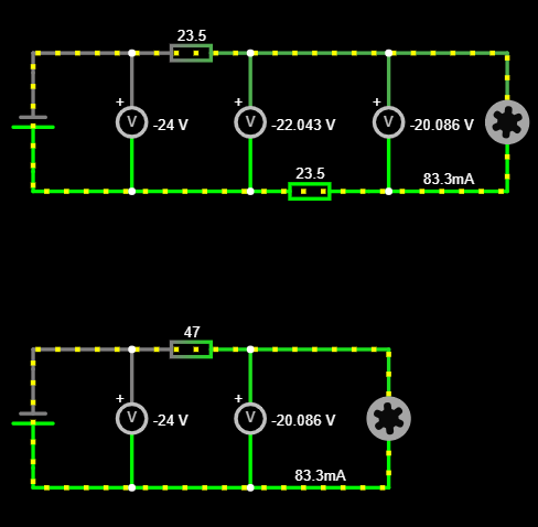
I was curious about the behavior here, hoping you can educate me on it. I’m not an electrical engineer and only have a rudimentary understanding of the electronic parts. I knew if he added two resistor at half the value (in series, one before the motor on positive side and one after the motor on ground side) it would drop the total voltage the same across the circuit when measured at the ends, but what I don’t know is the specifics of how the motor voltage would be in such a scenario.
In the DC circuit in a PC (since he said it is a PC fan), you have positive and ground (so 24v and 0v). So the voltage is all coming from the one side (positive) and the current is moving in only 1 direction (unlike in AC voltage system). So, if he were to add a 23.5ohm resistor before the motor on the positive side and another 23.5 ohm resistor on the ground side after the motor, the whole circuit voltage will drop 3v when measured at the start of the wires in the circuit. Same as if he had a single 47ohm on only one side. I get that part. And of course disregarding adding a resistor to a ground line and the safety issues with a high resistance ground wire, which is not normally good practice anyway for obvious safety reasons.
But, since one resistor is after the motor coil, will the motor receive the same voltage in both resistor scenarios? I would think that the first resistor will drop the voltage, the voltage then goes to the motor coil, runs through it, hits the second dropping resistor and then goes to ground to complete the circuit. So would the motor coil see 21v in both scenarios? Or since the voltage is only coming from one side would the motor coil in the 2 resistor scenario only see a 1.5v drop at that point even though the whole circuit has a 3v total drop by the end?
Now that we got the specs, what material resistor is preferable? Metal, carbon, etc. Brand suggestions would also be helpful since I’m ordering off Amazon.
A possibly more convenient way to do this is with a few diodes. They’ll just each drop the voltage around 0.5V each, no matter what the wattage of the fan you connect.
Perhaps even better (certainly more efficient) would be just using a $1 DC-DC buck converter. They’re pretty cheap at common DC voltages these days:
What voltage a device sees, is always relative to its local ground. It makes no difference if you add resistance to the positive or negative side as far as the fan is concerned. The only difference would be if/when some other device with a different ground potential comes in contact with it.
I already picked up a decent adjustable buck converter, but it would be very inconvenient to try and wire it up. Given the space constraints I would have run wires up and down the loom and mount the converter externally.
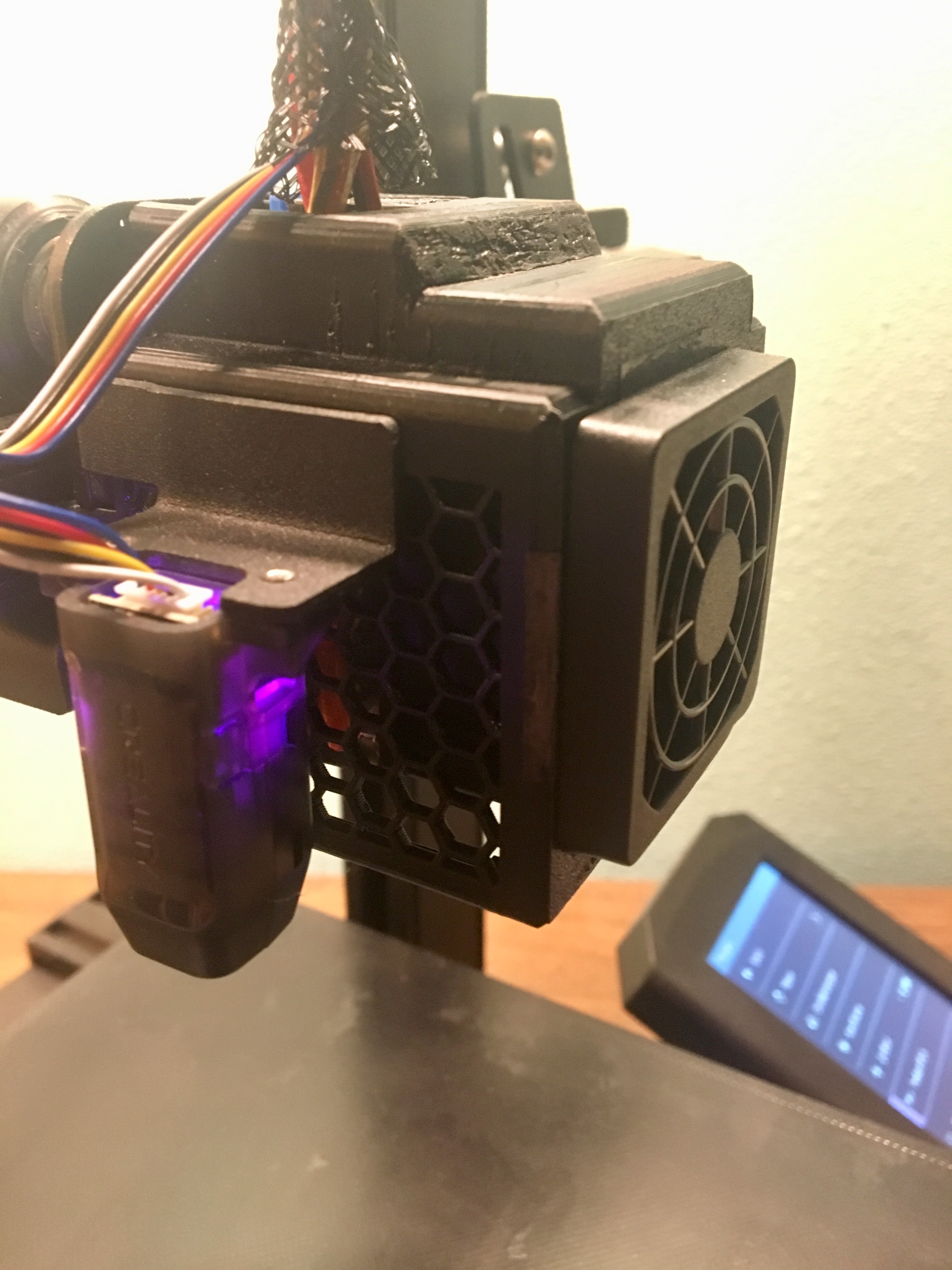
The 47ohm resistor worked exactly as it should, but there is still a really bad whine from the fan. I think I can add a filter and still have enough airflow over the hotend heatsink.
A 40mm filter was $3 off Amazon and I attached it using Tasco double-sided screen tape. It looks surprisingly aesthetic, but the extra tape will collect dust and pet hair eventually.
At least now I can sleep better with my bed-slinger running overnight in my room. Thanks everyone!