The ME is no security concern after you’ve cleaned it and perhaps shrunk the IFD section depending on what you plan to do.
With the HAP or cutting it down to the ME BUP modules it only serves to boot the PC and just hangs up after that.
The ME is no security concern after you’ve cleaned it and perhaps shrunk the IFD section depending on what you plan to do.
With the HAP or cutting it down to the ME BUP modules it only serves to boot the PC and just hangs up after that.
The CH341A can supply 3.3 and 5V with enough juice to flash everything I have come across so far, without needing to desoldering any pins.
Got myself a clip that plugs onto it.
1.8V Eeproms are still a problem though.
OOF. That adds a lot more work. Wouldn’t it be possible that by updating the bios, firmware’s elsewhere on the board were also updated, and I can’t revert those?
So easy to break, from personal experience… They never use fuses anywhere, so it always kills important IC’s 
Why are they a problem?
Time for some daily dose of do what I say not what I do as well:
I’ve flashed 3.3v chips at 5v and they’ve survived. I’ve wired SOICs backwards with my Pi and the motherboard didn’t smoke on Pi clip. I’ve applied board DC to laptops to not only prevent the board sink from eating up the limited current available to me to flash the chip but to also speed the flash/read greatly and to fix a “hole” in a bad stock BIOS SOIC. Still good to this day after a full DC applied flash.
Little things are hardy and most business class hardware can take some errant bullshit on the wires it seems.
If you fuck something up with the clipping/ chipping don’t sweat it. It’s probably okay just take it from the top and try again, slower this time.
My main concern is that with BIOS version 3.88 (~2016), pre Spectre/Meltdown mitigations, HP added a check for “unsupported combinations of processor and Management Engine firmware”, that if failed will halt the boot. I believe what they mean by unsupported is ME firmware v7 (Sandy Bridge) with an Ivy Bridge CPU. ME v8, from what I’ve read, supports both Ivy and Sandy Bridge CPUs.
So depending on if ME v8 is flashed as part of the normal BIOS updates, previously 2011 boot block systems with a BIOS >= 3.88, 2013 boot block flashed, and Ivy Bridge CPU installed might not boot at all. I guess putting the SB CPU back in would fix the boot prevention?  .
.
Should be fairly easy to check in advance what ME version is present, and also avoid the issue entirely by using BIOS 3.85.
I’d love to disable the ME anyway, so it’s nice doing the bootblock also makes it easy to me_cleaner and AltMeDisable it.
Good to know, thank you!
As far as I know all the firmware updates that happened, happened to the BIOS chips, which can be reverted by manually flashing. When you have time and are checking your Z420 BIOS version, can you find your ME firmware version too? I’d like to know if the official BIOS updates still update the ME firmware to v8 if a SB CPU is present. If so you can probably just use whatever BIOS version you’re currently on and avoid any downgrade hassles.
This is reassuring. Especially given the…laissez faire approach to errant bullshit prevention of Chinese tools.
1.8V eeproms are Problem because you need a level shifter to get them working.
At least if you want to do it properly without risk.
They run on 1.8V and logical high is therefore also 1.8V which isn’t necessarily enough to register as a High for the 3.3V reader / programmer.
It could be that it works but i don’t want to find out.
Found a random .ru website with a good summary of the Z820 upgrade thread (also applies to Z420/Z620): http://xdel.ru/downloads/z820/README.txt
  Some old revisions of the Z820 board lacking Ivy Bridge support while
no board-level obstacles are present to block this possibility. The fix is
purely software-based, you need to extract 64kB bootblock starting on
0d16711680 (0xff0000) from BIOS image with exact version to that you are
currently running and update an appropriate location on the NOR chip. Few
things should be considered in advance:
  - in-scheme programming for Z820 Winbond NOR is impossible, at least with
safe current margins on programmer, so make sure that you will be able to
desolder the chip or at least disconnect its Vcc pin in non-destructive
manner before clipping it to the programmer,
  - ME firmware must be updated to 8.x prior to reflash, if you are using
Linux, be sure that mei_me is unloaded and blacklisted during upgrade,
also deconfiguring ME in advance from BIOS menu is probably a safer path,
  - MAC addresses, system UUID, system serial number and SAS controller
identifier are better to be written down if no prior image dump is taken,
this should help to identify image locations where appropriate IDs are
stored or from what they are derived from after unsuccessful flash attempt
- binary difference by itself between downloaded image and image retrieved
from flash is relatively large and trying to figure out where identifiers
should be updated is easier when these identifiers are available beforehand,
  - all flash regions except ME are readable (and possibly writeable) from
OS, but some soldering work is necessary if board is bricked anyway.

It generally would not hurt to make an another software BIOS reflash on
after successfull bootblock update, as some checksums may become invalid
and update BIOS configuration by performing back-and-forth modification of
unimportant value.

bootblock-0394.bin - *new* bootblock, taken from 03.94 image, it is strongly
advised to meet exact firmware version because of SECURE_HP_SIGNATURE sub-block
which is specific for every image version (and probably for every unique system)

bootblock-0114.bin - *old* bootblock, all public firmware images, starting
from 01.20, contain a new version of bootblock

z820-flashrom-layout.txt - layout to dump specific regions using flashrom

This README is based on "z820 e5-2600 v2 ivy bridge upgrade" topic on
HP Support Community Home:

(https://h30434.www3.hp.com/t5/Business-PCs-Workstations-and-Point-of-Sale-Systems/z820-e5-2600-v2-ivy-bridge-upgrade/td-p/5086052)
It seems to conclude the gigantic passive drain of the Zx20 motherboards will draw too much current from basically any programmer. Several posts in this thread mention never having issues with programmer current output, so either the Zx20 boards have colossal passive drains or the accepted wisdom in the HP thread is wrong.
The recommendation is to be at least prepared to lift the Vcc pin or desolder the chip, which is a good possibility to be prepared for anyway.
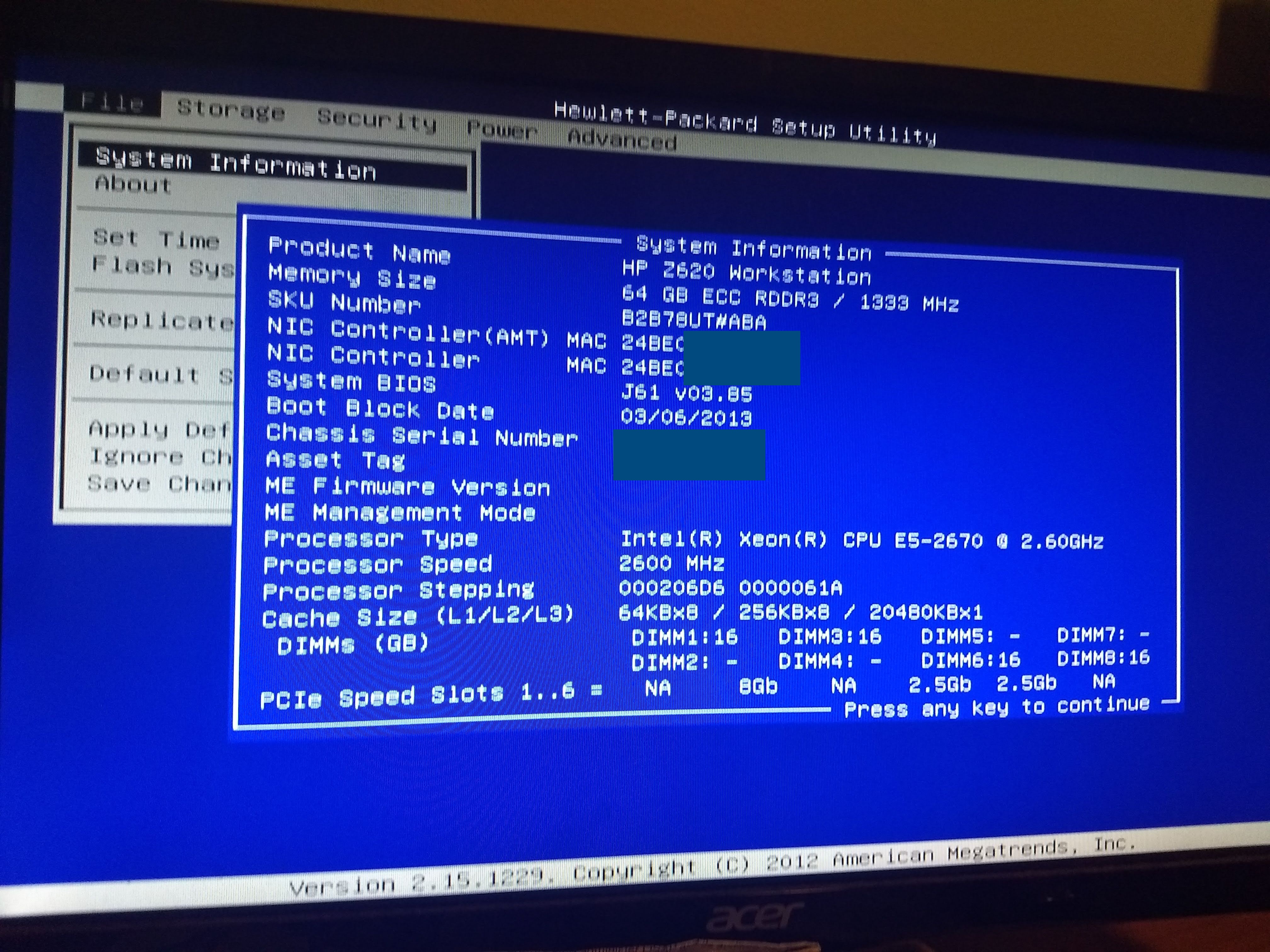
IT IS DONE!
BIOS v2.08 with 2011 boot block updated to v3.85 with 2013 boot block.
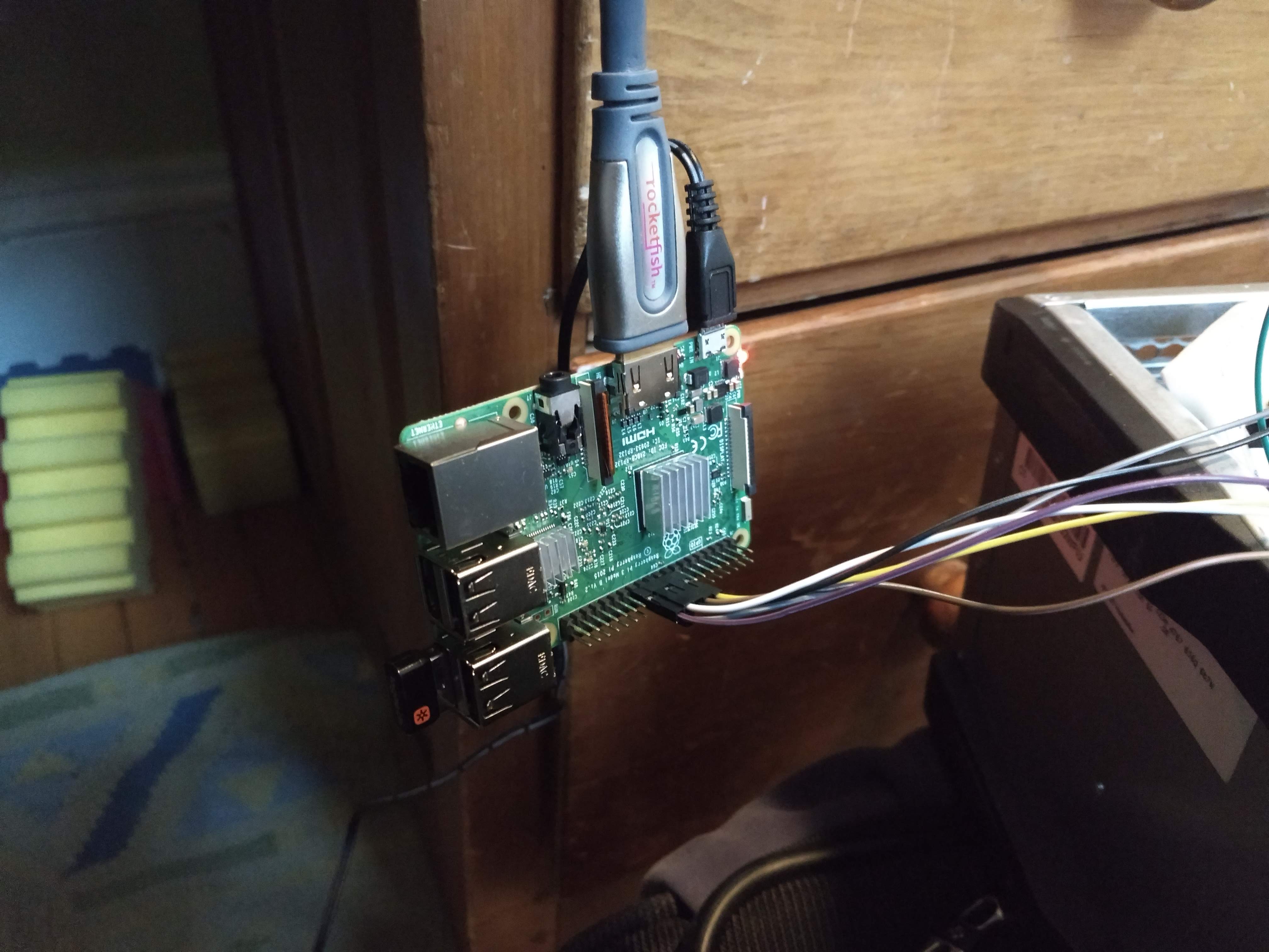
Tried both the CH341a and Raspberry Pi 3 but only had luck with the RPI3 - however this could be due to the SOIC16 clamp cable as I only got a good clamp after several tries on the RPi3.
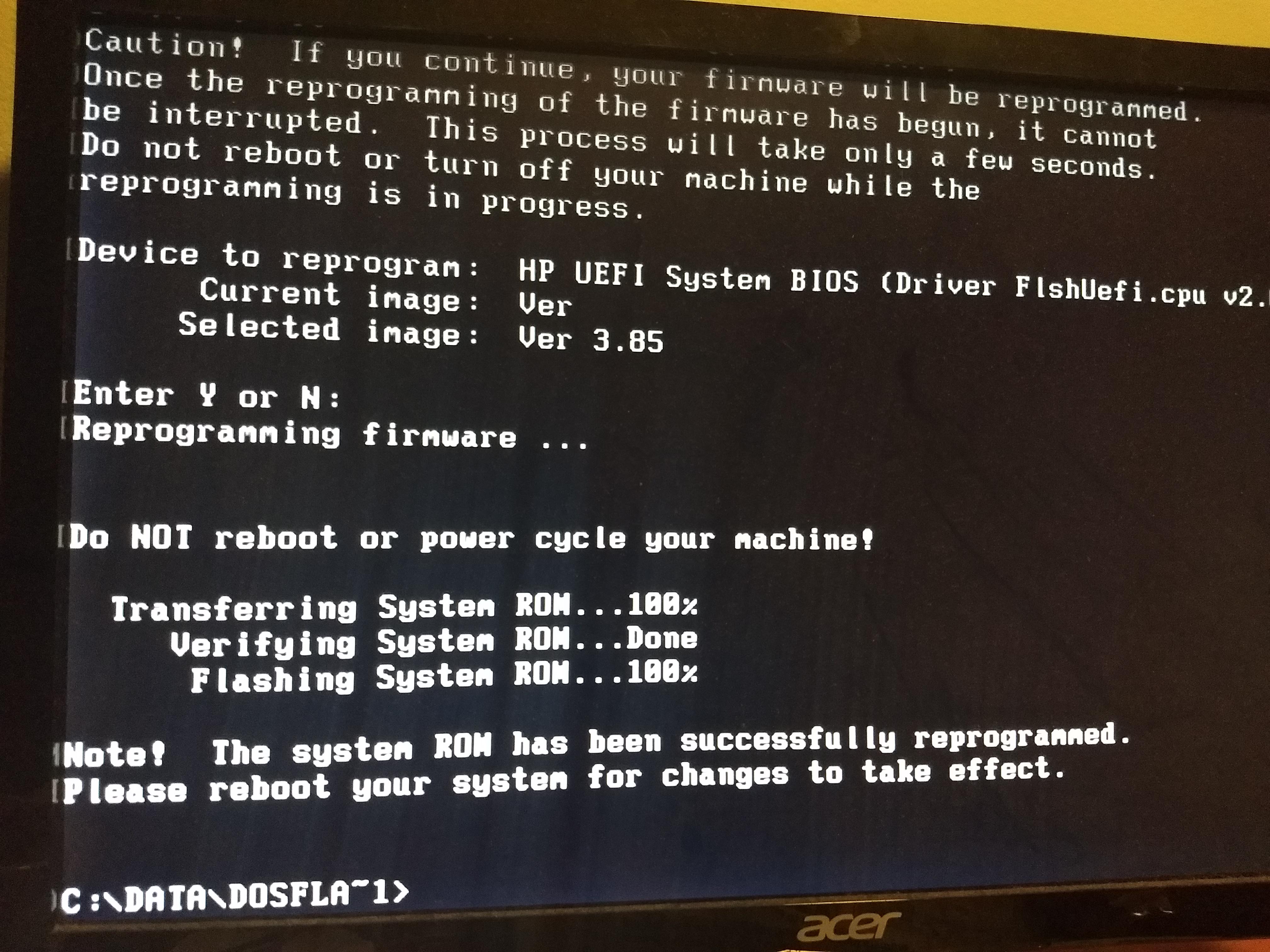
I made one mistake in forgetting to update to v3.85 before flashing the bootblock, resulting in the somewhat cursed result of a 2013 boot block on a v2.08 BIOS (from 2012, so this combination of BIOS and boot block is never meant to happen). But no worries, the Z620 still booted, and I made a FreeDOS liveUSB to use HP’s BIOS update utility and update to v3.85.
I also completely messed up the pinout on my first go with the CH341a and the chip seems fine. My CH341a is also the type (black PCB) to use put out 5V on the logic pins no matter what, so my SPI chip definitely experienced some errant bullshit with seemingly no permanent effects.
I don’t have a Xeon E5 v2 to test with, but at this stage they should all work with no issues. Waiting for the high core count ones to get extremly cheap on ebay 
I’m currently writing up a guide, will post in a few days.
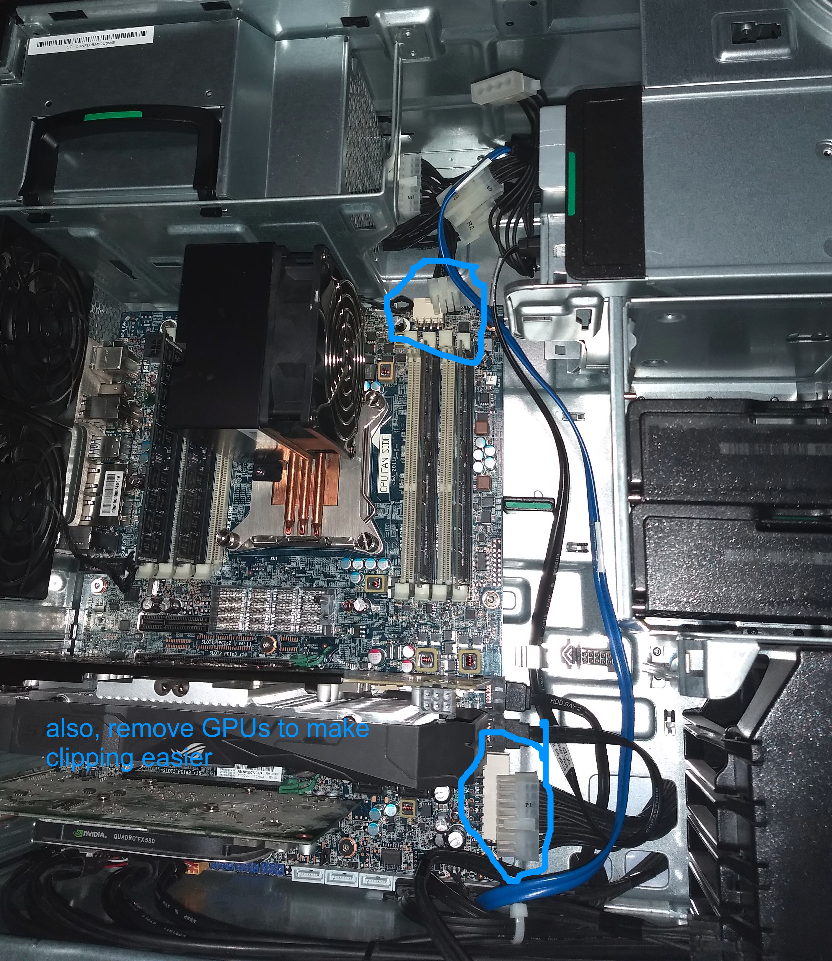
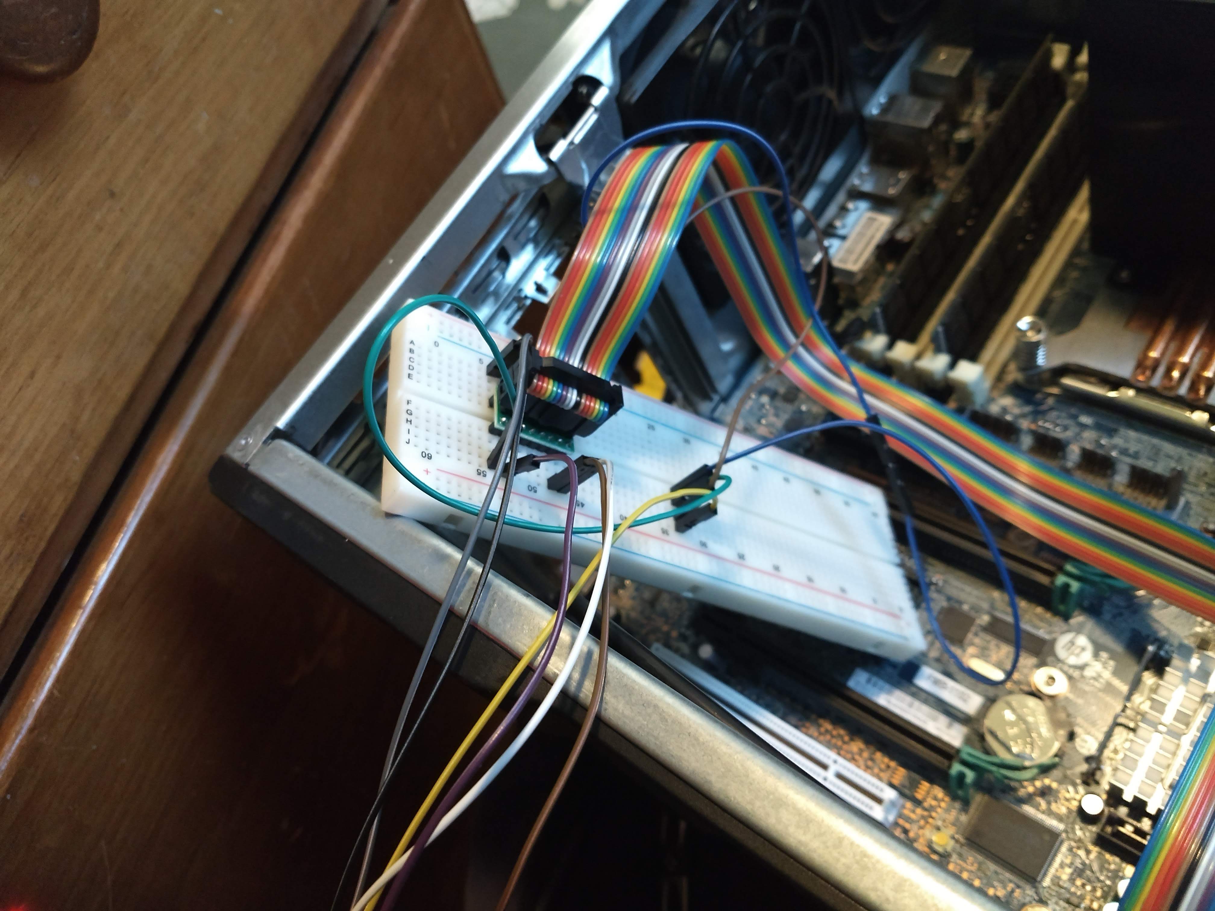
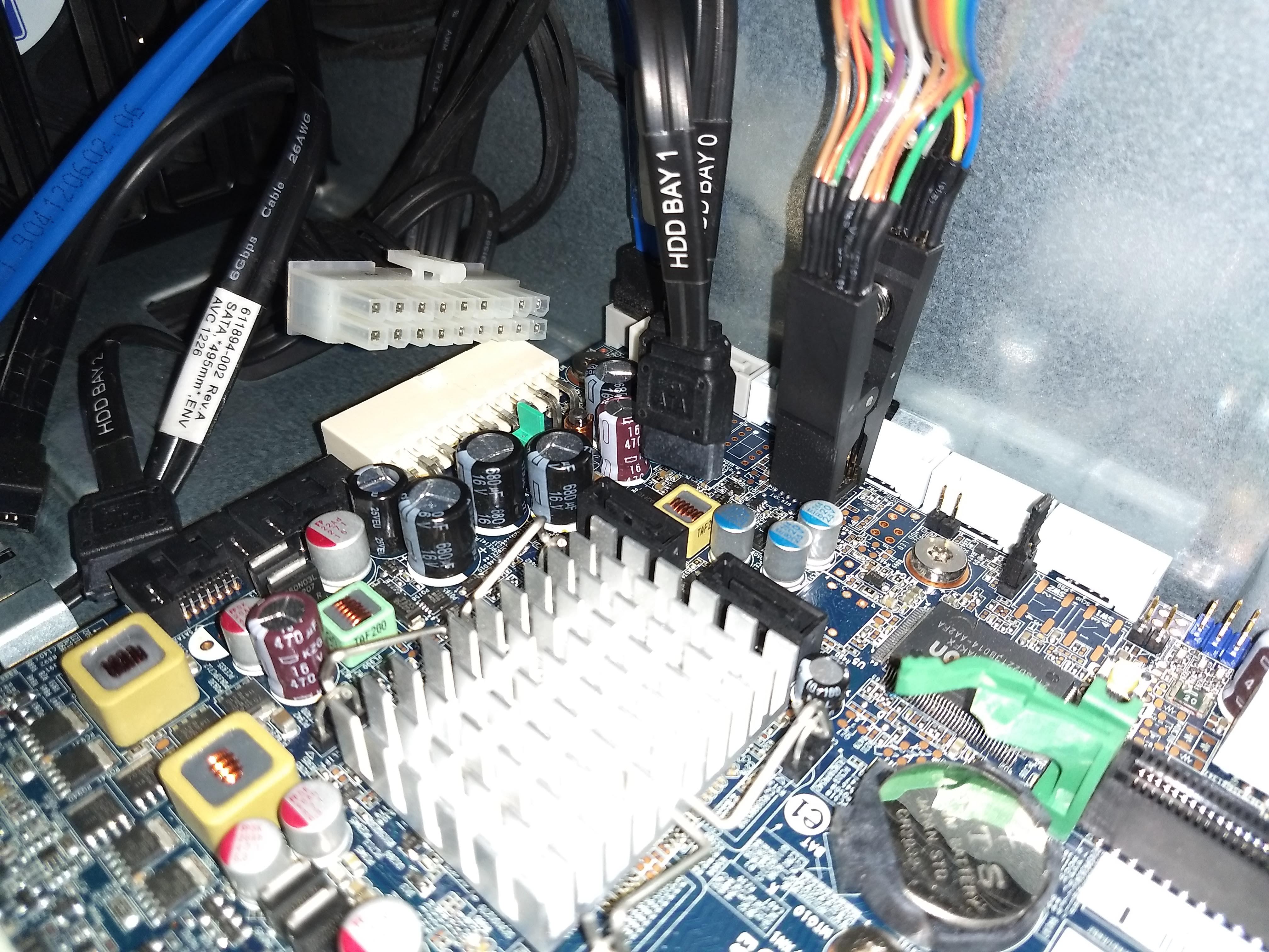
Here’s some pictures of the process for now:
Do the BIOS update to 3.85 first (unlike me)
Unplug the motherboard power connectors to minimize passive load on the SPI programmer and decouple from the PSU.
When I finally got a good clamp it was with dangling RPi3, so I let it dangle for the 2-3 hours it took after that.
I was worried about the length of the jumpers but in the end it didn’t seem to be an issue
On the whole I think this was still worth it over desoldering or lifting pins
Version 1.0 of the guide is done!
See the PDF in https://github.com/SuperThunder/HP_Z420_Z620_Z820_BootBlock_Upgrade
Anyone with basic windows, linux, and breadboarded electronics experience should be able to follow it. Feel free to post comments/questions/suggestions in the github issues tracker for the repo.
I discovered a way to update the boot block by software only, but it is a harsh method - you either succeed completely or your computer won’t boot anymore and you need to follow the hardware programming method. Still, for those who know what they’re doing it should save a lot of time.
i have a z420 v1 and am trying to make it v2 cpu compatibles the sw/easy way but idk where to start if anybody can help me i would appreciated. i purchased a 1603 v1 cpu just for this purpose, thank you.
Hi! I would recommend you look at the hardware method instead, especially if you don’t have a lot of experience. The software method is not as reliable as I initially thought, see https://github.com/SuperThunder/HP_Z420_Z620_Z820_BootBlock_Upgrade/issues/3 .
Essentially it seems that there are additional protections against modifying the boot block, even when using the header meant to disable all protections.
Did you read through the guide PDF?
I’m trying to go through this now myself, but am running into a wall when reading the SPI chip. I have used my multimeter to verify all my breakout board connections. and I’m pretty dang sure my chip clip is on correctly. Following the guide off of Github.
I’m using Manjaro ARM on a Raspberry Pi 3b.
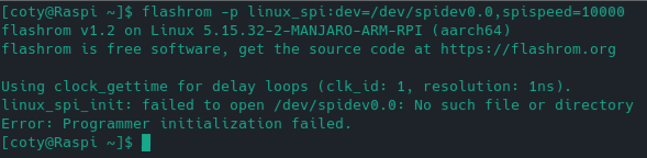
Whoops I’m a Raspberry Pi noob and didn’t realize I needed to enable SPI first.
Did that and now am getting “EEPROM/flash device found” so I probably need to recheck all my connections again. Sorry for pinging everyone on this old thread.
Is this too much of a necro revival, LOL?
A modded BIOS can boot now for Z620, see the discussion of that in that same GitHub page that hosts the pdf.
I created a GitHub repository. I cannot post links yet. The repository name is:
[HP_Z420_Z620_Z820_BOOTBLOCK2013_BIOS_mod]