Previous posts & pictures:
https://forum.level1techs.com/t/what-are-you-working-on-today/167475/81
https://forum.level1techs.com/t/what-are-you-working-on-today/167475/97
https://forum.level1techs.com/t/what-are-you-working-on-today/167475/100
https://forum.level1techs.com/t/what-are-you-working-on-today/167475/136
1 ) Mapping the screw holes:
Most of the bottom lid screws form a nice rectangle, so I started with those.
I’ll refer to them as ‘aligned’.
I used calipers to measure the relative distances between the aligned screw holes.
I rounded all my measurements to the closest 1/4th of a mm.
The trick is to take two measurements (one with the outside jaws and one with the inside jaws), then add them up and divide by two.
This still works if the hole sizes differ.
I then mapped all the points in CAD.
For each unaligned screw hole, I picked two pairs of two aligned ones, forming two triangles.
I then calculated the triangle’s heights and mapped the point.
2 ) Designing the laptop components in cad:
I chose to design two models for each component:
- An accurate copy of the component, to be used for validation.
- A slightly larger copy without the small details, to be used as the negative in boolean cuts.
The trackpad was glued to the chassis and that raised a few concerns:
Would I be able to remove the trackpad?
– Yes, just heat it up with a hairdryer and carefully lift it.
Would the trackpad work with a chassis made of different plastic and a different glue/adhesive tape?
– This guy did something similar with leather and wood: Leather Touchpad
No local retailer had the threaded inserts I needed, so I got an assortment kit from china.
The OEM manufacturer didn’t provide any design instructions, so I used this document I found online:
The most difficult component to design was the keyboard:
It has 84 keys of varying sizes, requiring 83 holes.
The keyboard assembly is secured to the chassis using meltable plastic rivets and 4 screws.
It’s also made of two separate parts, the keys & pcb and a steel support plate.
The keys & pcb layer requires very thin rivets that I can’t print :(.
The support plate requires larger rivets that can be printed reliably.
The left hinge had a steel kensington lock.
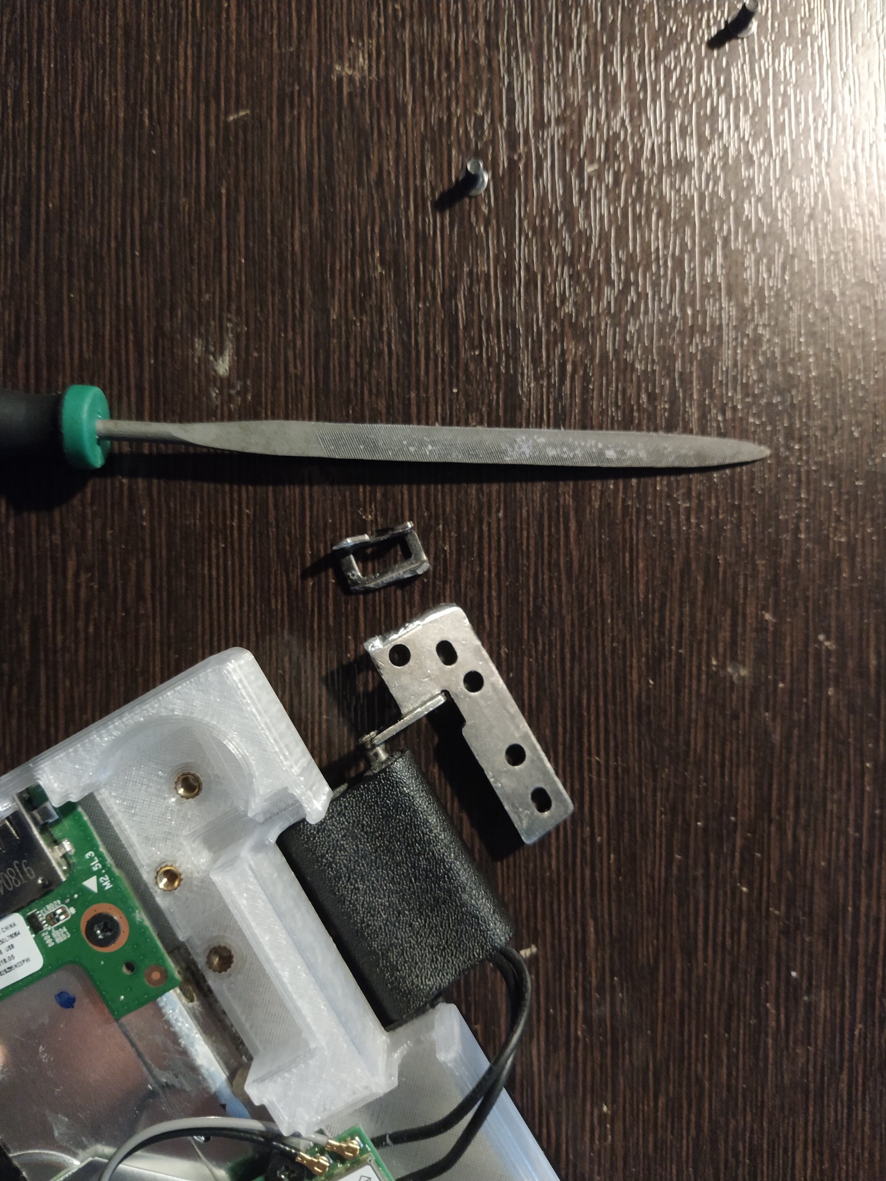
I removed it with a file, because it got in the way.
Pro criminal tip: Angle the file a bit, so that it won’t get wedged in there.
I used the point map of screw holes to position all the components in CAD.
There were some conflicts and I had to redo a lot of measurements.
3a ) Slice it:
It barely fits in the build area of my printer.
I had to add some support blockers & enforcers.
The keyboard can’t be printed with a bridge and needed actual support rafts.
The trackpad wasn’t printable, and I had to make it flush with the wrist rest.
3b ) Print it:
I dehydrated the plastic for 1 hour in the oven.
I applied a thin coat of stick glue to the print bed, to ensure first layer adhesion.
The chassis took ~22 hours.
The bottom lid took ~12 hours.
I used a file and pliers to smoothen rough edges, remove support structures and fix design mistakes.
3c ) Mistakes:
Some dimensions were off because I used worn-out plastic calipers.
The wifi card wouldn’t fit because I was too lazy to design it in cad.
I also forgot to add space for the speaker cable.
i.e. goto step_2
4 ) Assembly:
How to install threaded inserts:

I melted the plastic rivets with a standard soldering tip.
It turned out ugly, but it’s not visible from the outside, and it works.
I was able to reuse the trackpad’s adhesive tape, though I’ll probably replace it later.
5 ) Conclusion:
Holy sh*t, the frame feels sturdy as f*ck.
There is keyboard flex due to 3d printing limitations, but the rest feels surprisingly strong.
In step 2, I didn’t design all the keyboard rivets, and now the keys can shift very slightly.
I think I can bend the support plate to hold them in place.
I want to see how well the hinge threaded inserts will hold up.