After testing MANY USB 3.0 controllers and researching which ones work best with VFIO, I’ve now landed on this solution for the ULTIMATE VFIO USB 3.0 controller card.
I had another thread where I vented out my frustrations with XHCI and Linux, and that has a little bit of info on woes regarding which controllers 100% work for VFIO and GPU passthrough:
Through all that frustration, I came to the solution for a proper USB 3.0 controller for QEMU/KVM passthrough… The Startech PEXUSB3S24.
This supports Message Signaled Interrupts which is required for consistent data streaming. (USB Video and Audio data for instance) Interestingly, the same concept as that applies for the HD Audio controllers on GPUs which also need Message Signaled Interrupts to prevent audio streams from becoming garbled/warped.
This card is also one of the rare USB 3.0 controller cards that support proper resetting, which means reboots of the VM won’t cause any system lockups or other issues like the 127 issue. I tell you, coming from a Fresco Logic controller that didn’t support proper resetting… (even though it may indicate it can support resetting when listing it’s PCIE functionality) having to cold boot the machine everytime to boot the VM was a nightmare.
The reason this works so well is because the controller comes pre-loaded with the latest firmware (even newer than the 2.0.2.0 firmware on Startech’s site) and is based off of the uPD720202 from Renesas. This controller also requires no manual installation of drivers for Windows 8.1 and Windows 10 VMs. I believe Message Signaled Interrupts are also automatically switched on when you reveal the card to Windows.

Problem 1 solved. We now have a proper USB 3.0 controller that with the SATA power connected, gets around USB power management issues…
But we have more than one problem on our hands… Our 2nd problem is fitting this card underneath a MASSIVE GPU like my STRIX GTX 1080 11Gbps…
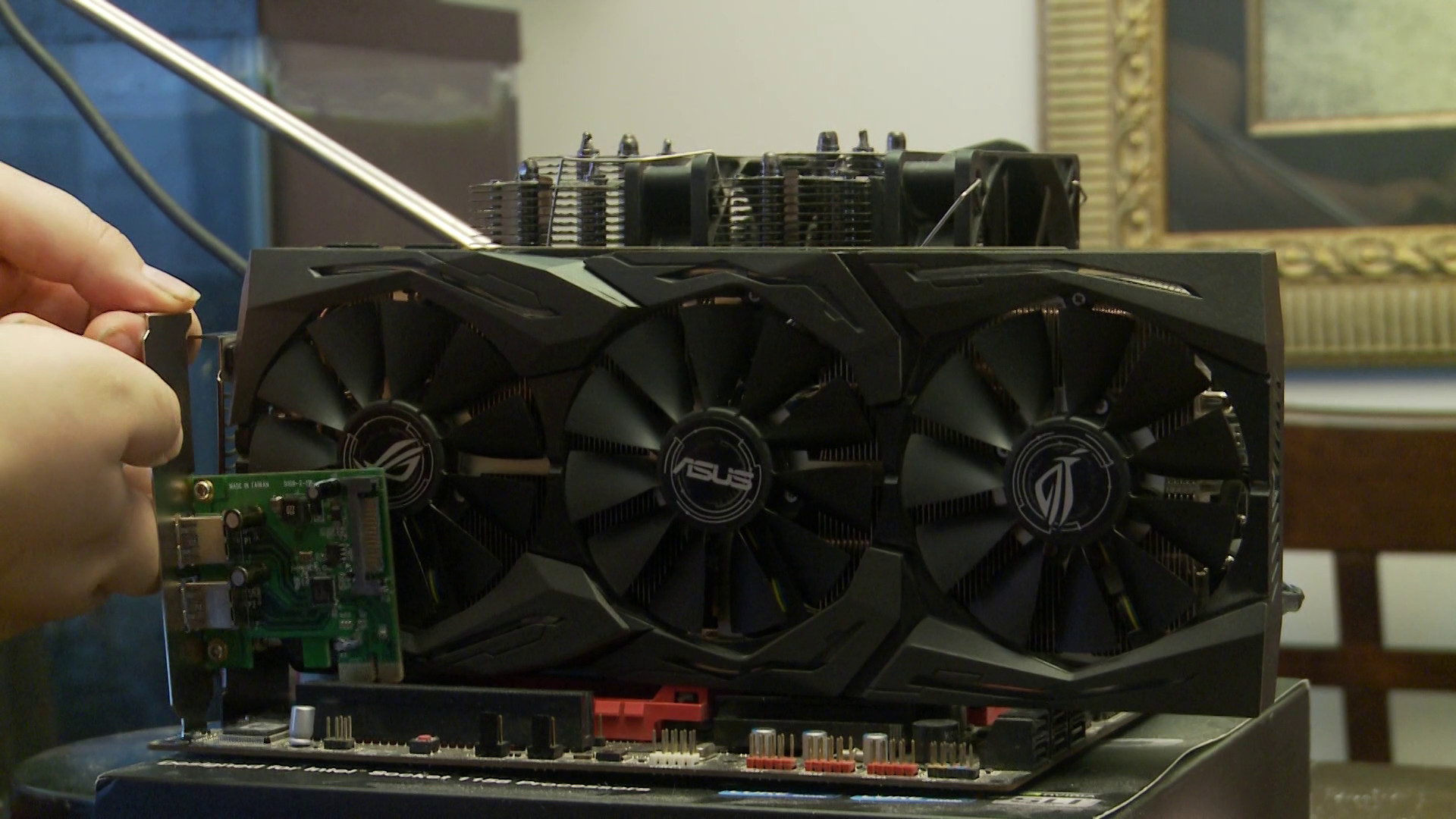
Because I have to use the x4 slot on my Gigabyte GA-X79S-UP5-WIFI with my Decklink Mini Recorder 4K and the 2nd x16 is taken up by my GTX 1060 6GB for the host OS…

3rd slot is the x4 (Overclock3d)
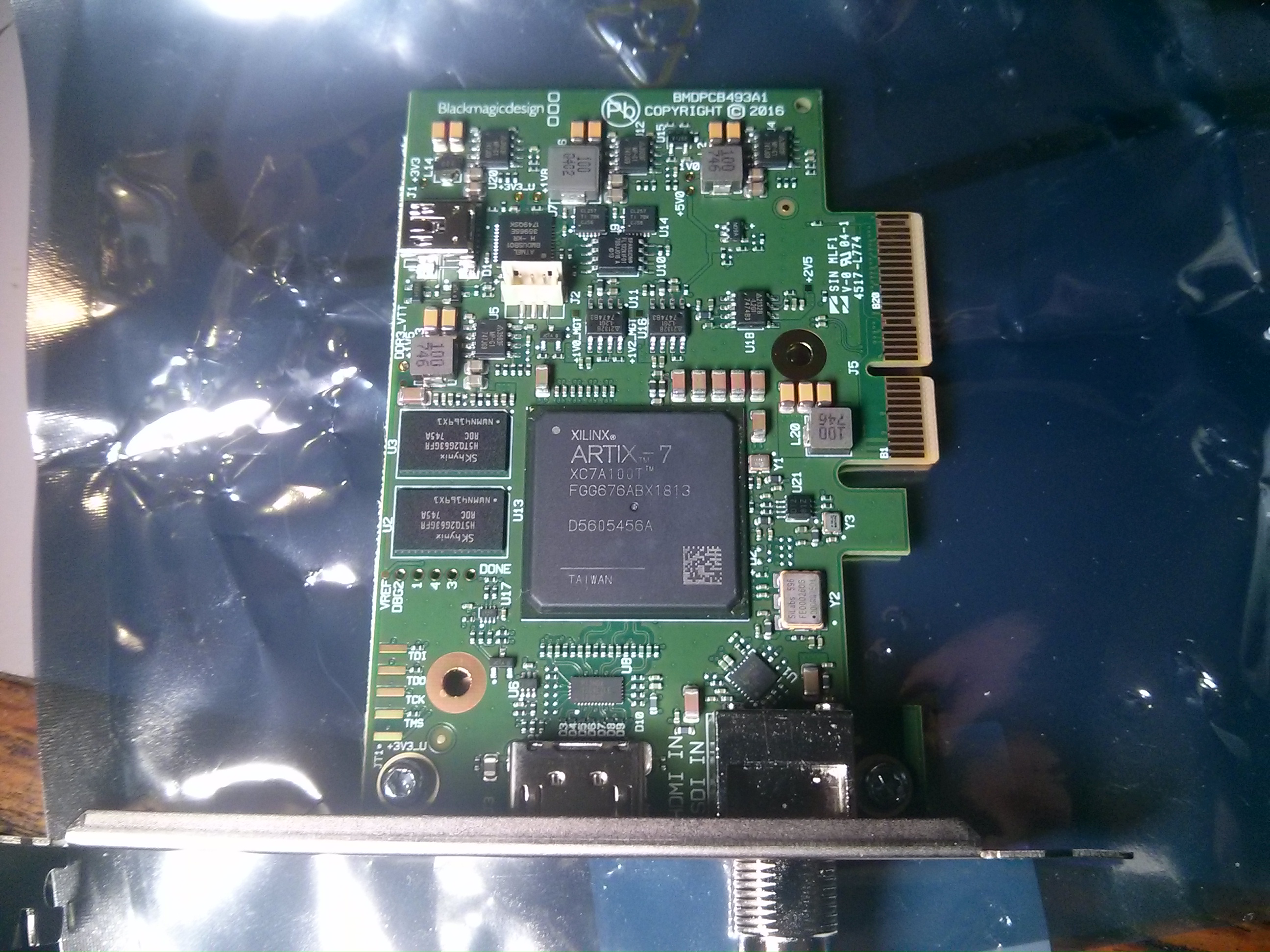
Decklink Mini Recorder 4K, no heatsink. (I applied thermal paste to it and removed the original thermal pad/thermal glue)
Solution 2? Use a x1 PCI-E Riser with an ultra low profile slot!
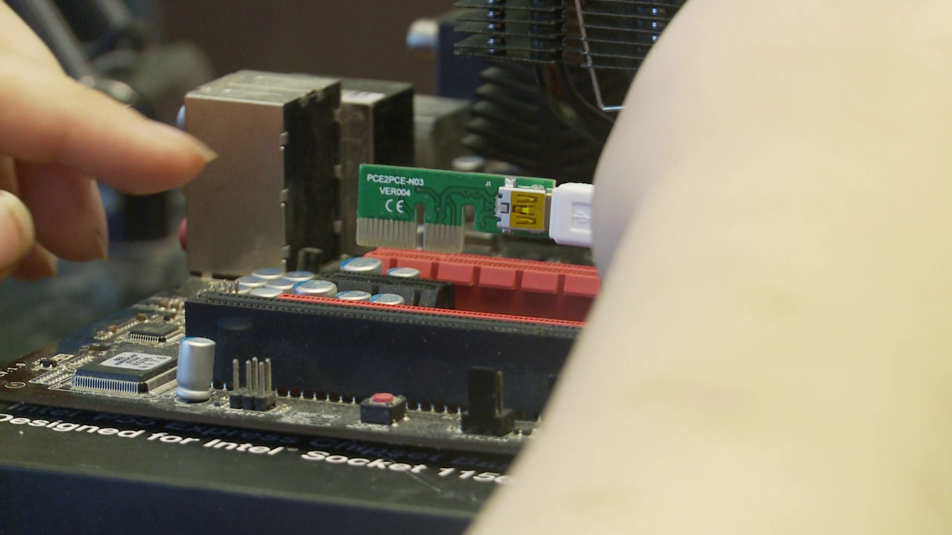
This is the XCSOURCE AC1291 PCI-E Riser. It also goes under the name Etmakit on AliExpress and ENLabs on Newegg.
(UPDATED LINK)
So this thing allows you to use the x1 underneath your GPU, while reconditioning the power for the slot at the relocated slot, rather than trying to send both data and power down a ribbon cable, and a ribbon cable sure as heck won’t be flexible enough to reach the secondary chamber of a case with the PSU in a separate chamber.
Make sure to replace the bundled SATA power to Floppy power connector with a Molex Power to Floppy power connector… because MOLEX TO SATA, LOSE YOUR DATA. You can find good Molex to Floppy connectors with most PSU cables, and some PSUs even have Molex PSU cables with a Floppy connector at the very end of the cable. There’s no excuse for not using a Molex to Floppy to power the riser.
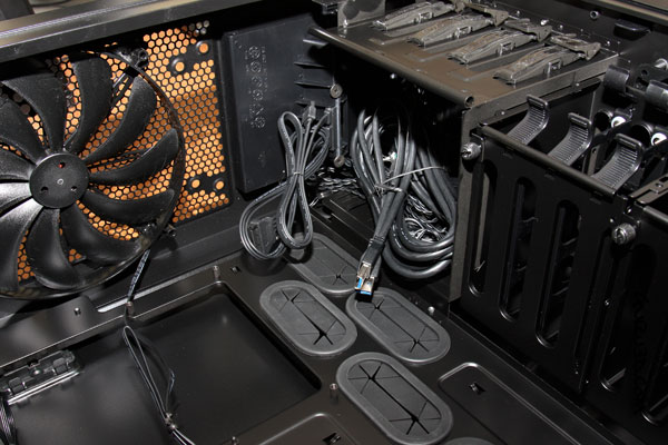
Also make sure to unscrew the supplied PCI bracket on the Startech card so that it can fit in the secondary compartment of your case without colliding into anything.
If you’re trying to remain aesthetically pleasing, a USB controller in a vertical GPU mount using a ribbon cable would block a full view of the GPU, and might even cause airflow issues.
A Superplus ribbon cable riser, with the USB 3.0 controller in the primary chamber. IMO, an eyesore for aesthetic focused builds.
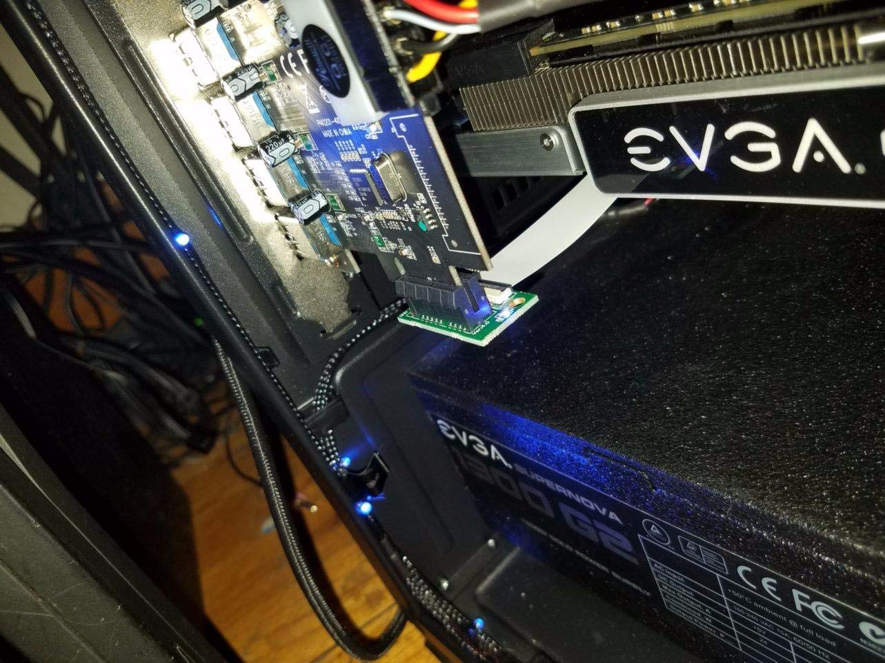
With this low profile (not ribbon cable) riser configuration though, problem 2 is solved while still looking nice. Because the Startech card is only half-height for a half-height PCI bracket form factor, (even though we’re not using the PCI brackets supplied) the standardized height of ATX power supplies (which also has some breathing room for the PSU fans) in cases like the Air 540 and Lian Li O11 Air and O11 Dynamic, helps half height PCBs fit in the secondary compartment without having issues of being unable to fit. This is a critical reason why a 2 port controller works for this and a taller 4 port controller wouldn’t work for this.
There’s another problem though… Relocating the controller to the secondary chamber means you can’t access the USB ports on the controller without taking a dremel to the side panel. I don’t own a dremel and I live in an apartment. Neighbors would be VERY unhappy with dremel case mods on my balcony and I could even violate strata codes with the shrapnel flying around…
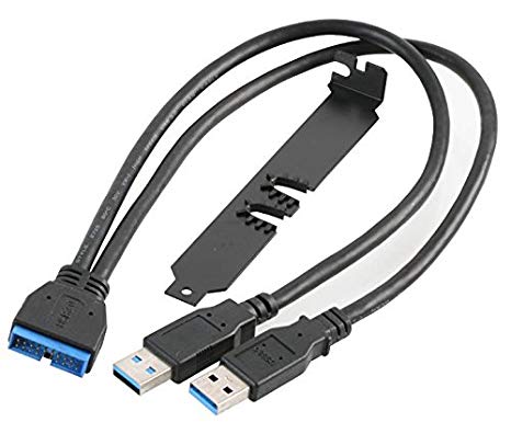
Solution 3… (without resorting to case mods) Turn your case’s USB 3.0 ports from an internal header back into USB Male A connectors with this thing:

This is a Akasa AK-CBUB12-30BK. A 2x USB Male A to USB 3.0 internal header cable.
(UPDATED LINK)
This cable was originally meant for trying to solve a problem X58 and P55 motherboard and case manufacturers made for themselves when USB 3.0 was only available through USB A ports on the back I/O, but then most cases at that time were following that trend… They just extended the front USB 3.0 ports with USB 3.0 Male A extension cables rather than using an internal header…
Inside the Corsair 650D, with USB 3.0 Male A connectors for the front panel I/O (Guru3D)
But times then changed, a header standard was adopted, and motherboards were slow to catch up… So if you wanted a new case like a Corsair 400R without upgrading your core components, but your old X58 or P55 mobo had no internal header? You get this cable.

In fact, it even comes with a PCI bracket with holes for the cable for this specific purpose.
Our purpose though is to use our case’s USB 3.0 header with the Renesas uPD720202 using this Akasa cable, and it totally works.
The video outlines the installation steps I took for the entire process in more detail, but in brief terms about the riser, it’s meant to only connect to x1 slots at the male end. While the riser fits without a cable connected in any length of slot, the cable connector thickness prevents it from connecting firmly to longer x4, x8 or x16 slots.
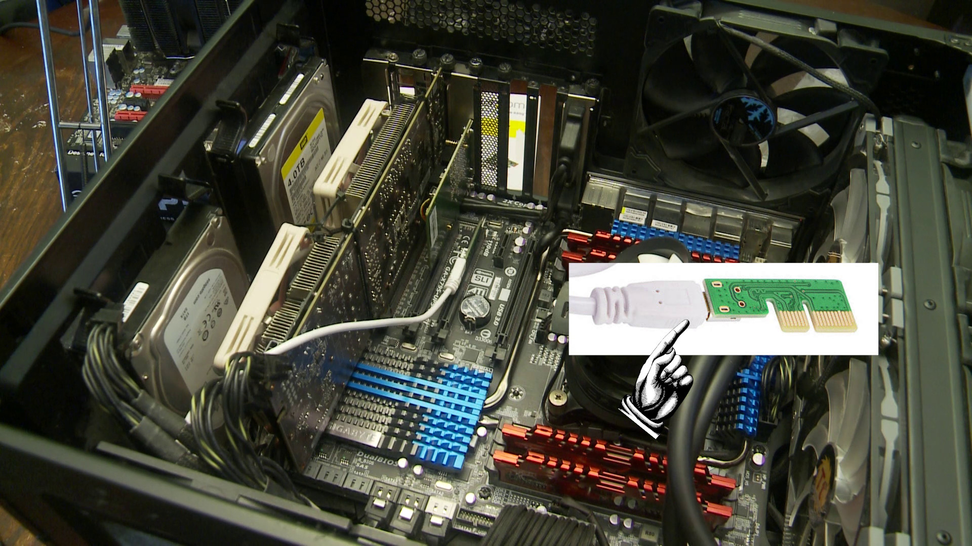
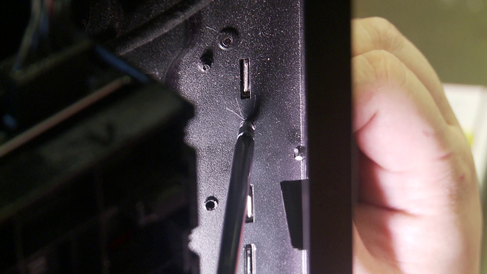
Cable routing the cable can be tricky because of connector tension. Too much tension can break the connector either on the cable side or the PCB side. Be gentle with it and there shouldn’t be any problems.
UPDATE May 2021: It appears a PCB that has a Mini USB 3.0 adapting to M.2 does exist with the PCB model number NGFFPCE-N02.

I have tested if this PCB and it is 100% cross compatible with the PCE2PCE-N02, so long as you use the bundled USB cable that comes with the riser. (The pinout of the special made cable is different from a standard USB 3.0 A to USB 3.0 Mini-B) Sometimes large GPU fan shrouds will bump into the PCE2PCE-N03 if you’re putting it directly 2 slots down, so if your board has M.2, that’s a better way to fit under particularly large GPU fan shrouds.
UPDATE October 2021: If you need the M.2 PCB, eGPU[dot]io has a link to it in their thread:
In fact, cable management of the Akasa cable in my Air 540 using the 5.25’’ bays allowed me to not use any electrical tape to protect components, as the tension of the cable was enough to guide the PCB away from the metal parts of the case. There’s foam/felt padding at the bottom of the end of the riser where the controller card slots in, so that PCB has a low risk of an electrical short, with the risk made even lower by the rubber grommets that PCB is resting on when I move the riser to it’s final position in the secondary compartment.
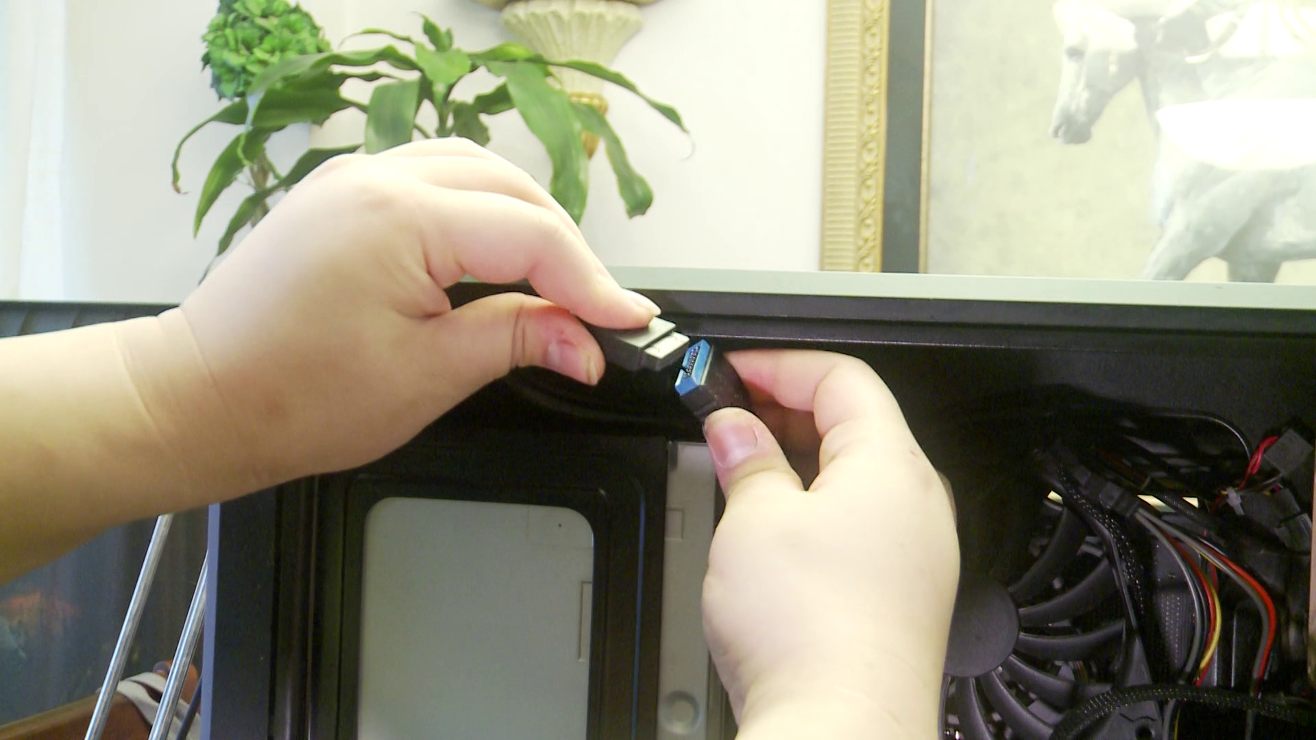
The TOP cable, with the “USB 3.0” written side of the internal header end on the Akasa cable facing you, is the first port. The USB Male A ports go in with the blank side facing the PCB side on the Startech with the Renesas controller visible.
A few notes though: Using a USB 3.0 hub with this config will degrade the data links enough that packets will drop, since the length is the length of the internal USB header cable, PLUS the length of the header cable to A cable combined. You may want some EMI shielding to prevent signal loss. USB 2.0 devices, and 3.0 devices connected directly with no hub, work fine though.
Also, don’t put the x1 in the x8 that has lane switchers between the x16 and the x8 slot on certain motherboards. It will limit your GPU in the primary slot to x8 even though you’re only passing through a x1 on that port. Threadripper shouldn’t have these issues, but Threadripper still has issues with using x1 slots going to the chipset. Fortunately, my setup is X79 which has proper hardware ACS for stuff going through the chipset.
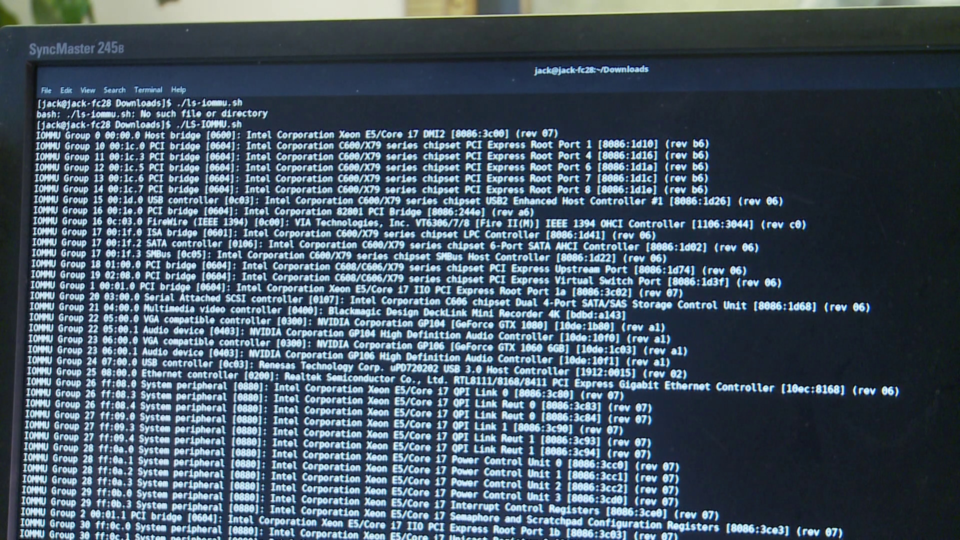
My IOMMU groupings
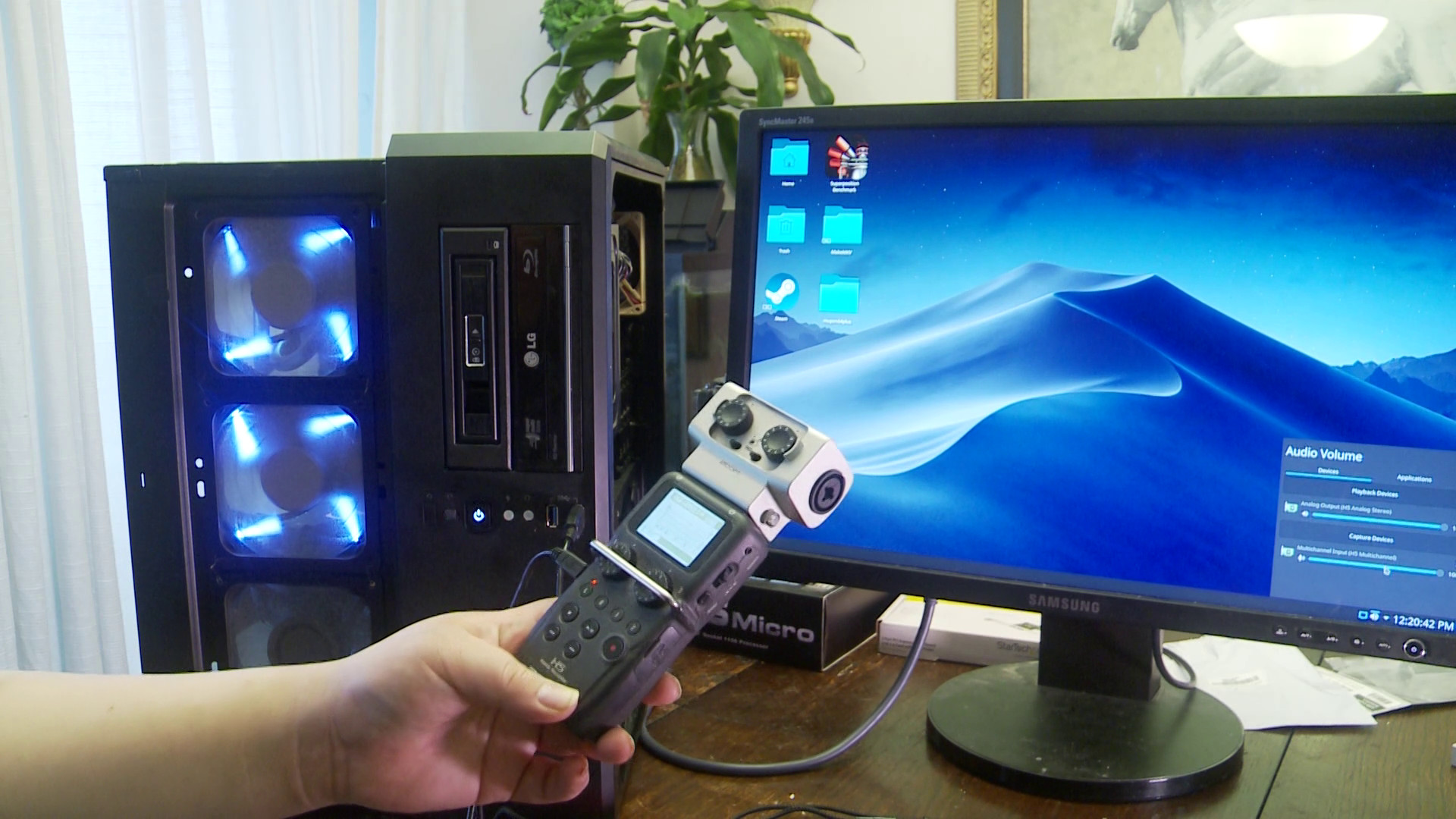
In my video, I show the controller working with a Kubuntu VM with my Zoom H5 in ASIO mode (24bit 4 channel 48Khz) able to produce sound when changing the volume, so I encourage you to watch the video if you’re only reading the article. The Zoom U-22 however will not work under the controller. You will need native chipset controller USB 2.0 passthrough for that.
I also go into tips for doing the Jayztwocents GPU sag trick if you’re planning to do it multiple times. (You may want to replace screws often)
This is the Jayztwocents trick for those unaware:

So, I’ve provided the links so that you can do this yourself… I’ve demonstrated assembly in the video just to show you how easy this is to assemble… I want to see VFIO builds with everything I’ve taught here put into action. I won’t be mad if you modded your case instead of using the Akasa cable. In fact, if it’s a creative use, I’ll applaud it! (As I said earlier, using the Vertical GPU mount DOESN’T COUNT. Leaving the controller in the primary compartment would wreck aesthetics, as BitWit Kyle might point out.)
If you’ve made a VFIO system with these components to make the “ULTIMATE” VFIO USB 3.0 controller, feel free to make a post below with that rig and how you managed to set it up!
Final note: Yes, you have to do kvm=off even for a Kubuntu VM. That’s how I got an Nvidia card to work in that VM. (Linux Code 43 still exists, despite the loosening of rules on Windows drivers)
UPDATED LINKS Dec 2020
CONFIRMED M.2 PCB works May 2021
ADDED link to egpu[dot]io discussion which has the purchase link to the riser kit with the M.2 PCB October 2021

