Your switch idea may be the right idea. Put a fast MOSFET in place of the switch and create some way to produce as sharp of a pulse as you can to drive the MOSFET.
Alternate route: Horse-shoe electro magnet, function generator and power amp.
Updated the first post. Will add how BIOS options impact things next.
Not really, the third iteration with a switch is already “ok” in all 3 aspects. It’s sub 10$, I can get 1-bit error every time and to use I just put the DIMM into a riser and that riser into the mobo slot - that’s it - push the button for errors.
But are other bad aspects of this approach:
Robustness - hot glue, protruding wires and weak solder joints make this fragile
It requires some dedication and soldering.
Low but non-zero chances of damaging components. (Power pins are fortunately not that common and generally grouped together)
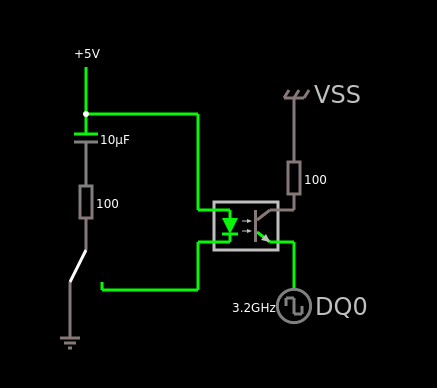
Fingers are fat and slow - As you said MOSFET would be much better and would probably allow for 2 bit errors that don’t cause instant resets. I was also thinking about using and optocoupler instead to not rely on common ground but that’s for something further down the line. (Not entirely sure if using dimm power pins or external power is better yet)
Yes, it will work, but this does not answer every question.
If mobo is secretly enabling PFEH then yes, ECC can be functional, being visible in dmidecode but even if errors occur they won’t be reported to the OS.
And if there is no BIOS option to disable PFEH it then you can only guess if you are experiencing “stability” or “instability hidden by the PFEH”.
Also a pedantic side-note about the “dmidecode -t memory | grep ECC” command (sorry): This will show multiple entries - for both physical memory and cpu cache. You want to check if ECC is declared in Physical memory section.
For example:
Handle 0x0013, DMI type 16, 23 bytes
Physical Memory Array
	Location: System Board Or Motherboard
	Use: System Memory
	Error Correction Type: None
	Maximum Capacity: 128 GB
	Error Information Handle: 0x0012
	Number Of Devices: 4

...

Handle 0x0015, DMI type 7, 27 bytes
Cache Information
	Socket Designation: L1 - Cache
	Configuration: Enabled, Not Socketed, Level 1
	Operational Mode: Write Back
	Location: Internal
	Installed Size: 576 kB
	Maximum Size: 576 kB
	Supported SRAM Types:
		Pipeline Burst
	Installed SRAM Type: Pipeline Burst
	Speed: 1 ns
	Error Correction Type: Multi-bit ECC
	System Type: Unified
	Associativity: 8-way Set-associative
Edit: @FooLKiller One more reason to do this: On server platforms with IPMI you would expect ECC errors to appear in the IPMI log. This is not something that can be taken for granted - my X470D4U IPMI does not log them.
Not really a super important aspect but it can save a lot of head-ache when for example a 2 bit error causes a reset/panic. Without IPMI log or an external serial console log prepared beforehand you could only guess what happened. (or worse - believe that empty IPMI log means there is some other non-existent issue)
Updated the first post with BIOS option results and resistor testing.
Also kinda annoying thing described there: with ECC disabled the riser with a button causes instant reboots/freezes. I can only get real uncorrected data corruption with static discharge. It is fairly easy but I guess this is the thing that needs a fast mosfet/transistor instead of a finger.
I am curious however if the weird resistor layout on Passmark prototype is something that would help with this…
Maybe you could use a capacitor for the glitching.
Instead of shorting pins, connect an uncharged or even negatively charged* cap to the data line.
The resulting load of charging the cap should affect the signal.
Kinda like reverse bypass caps in the “voltage glitching” area of expertise.
Negative Charges on the caps might damage the components?
First find out what voltage the data signal transmit at. After that, use a mosfet + mosfet driver to quickly introduce some random 1’s and 0’s, either using a arduino/RPi, or just directly connect a arduino/RPi to the data lines.
Not sure if you have already attempted this, but ensure that you’re using very short traces/wires to eliminate possible external interference.
Since I am not confident in my ability to design circuits safe for the components I would try to avoid putting any caps/voltage charge directly into data pins if I can.
connecting an uncharged cap with something is totally safe.
The Charging will ideally “drain” the data line and introduce a glitch that way.
The size of the cap controls the glitch length.
So yuo would have a cap connected to GND.
And you would then switch the other end between GND and the dataline.
Yeah, but this switching between ground and data line would have to be fast, can’t do it with my fingers if it is to be a better solution than a resistor.
Edit:
Basically I think that hand shorting with a resistor or hand shorting with a cap doesn’t really make a difference. (Or am I missing something?)
well, my initial thought was that the cap only charges once, so basically minimizing the effect from your switch action through its behavior.
So even though you keep the switch pressed for 10 seconds, if the charge time is 10ms, it would be charged after that and “not interfere” anymore.
BUT that thought is wrong.
Technically.
Because the cap will also discharge back onto the dataline when the signal goes LOW and charge again when it goes high.
Though i can imagine the initial charge to have a greater effect then the ones following it from staying connected.
It would depend on the size of the cap.
The larger the longer the charge and interference takes.
EDIT etech basics just in case.
In the exact moment you connect a cap to something, it behaves as a direct short. Infinite Current in that exact moment.
And from that it drops rapidly until the cap is charged.
The Voltage oposite, rapid increase to then slow down the smaller the differences in charge to voltage.
Have a look at voltage / current curves.
I think I get the idea but wouldn’t it only work if data pins stayed constant? Once they start going 0>1>0>1 the cap will be repeatedly charged/discharged causing multiple glitches
I can try though. Just don’t have a set of caps on hand ATM.
Didn’t really have time to order new parts yet but I wanted to report that on my other asrock board: b450m Steel Legend + 3700x ; Ecc is functioning and the reports are not masked by PFEH - so it’s disabled. (There is no PFEH setting in the bios).
So I want a new system with ECC and VFIO. So far it’s looking like I’ll be going for an enthusiast X570 motherboard. It’s been about a decade since I’ve done overclocking or dug around in those kinds of BIOS screens so maybe I’m missing something here but…
…what about undervolting the ram or overclocking it out of spec to generate bit errors?
Personally I’d feel a lot more comfortable doing that to validate the motherboard over shorting RAM pins.
Edit: this might work as a test on a server motherboard without as many BIOS options? Just get the slowest ECC compatible memory you can and try to run it at a higher available frequency? ehhh unless you have the memory sitting around already this is probably going to be a nightmare of compatibility. BuildZoid’s youtube “Rambling about DDR4 chips and PCBs” talked some about his problems of just popping in unvalidated memory that had a different DDR3 layout the manufacturer hadn’t tuned for.
@CyberTrog I agree, the easiest way is to lower voltage until ram is unstable enough. Lowering some timings like CL or RFC to the limit might also do it !
I recently pushed some CL22 3200 micron E-Die ECC UDIMMs to 3666 CL16 @ 1.40V and ecc errors proved very helpful to fine tune them (by not having to spend countless hours doing memtests !).
Reporting is working correctly on my board (asus proart x570, with default bios options) and, when unstable, WHEA 47 single-bit memory errors are reported in windows system logs. Some tools like OCCT memory stress tester are also able to pick them up which is great !
@CyberTrog@Ivanovitch_k
If OC/undervolt works then yes, it’s an easier way to setup.
But that will work only in some hardware/bios combinations.
Some boards’ memory training will be aggressive enough that the edge between stable and not-posting can be very thin.
And OC may prove only that the board is reporting errors if they happen.
But not if the board won’t rapport them.
To elaborate:
If the board you are testing on is not showing errors no matter how long you tweak the OC settings then you really didn’t prove anything. It may be that the OC is stable and errors aren’t happening but the board would report them if they did.
Alternatively the errors are happening and are being corrected silently without any reports (PFEH)
You just can’t be sure which one is true.
Besides it takes time to balance the OC (assuming you have OC options in the BIOS).
Shorting pins is fast and takes out the guesswork.