Awhile back I came to possess a pair of Cheetah 15k.4 drives. I thought it might be fun to use these in a dumpster dive/eBay parts system so I’ve been slowly obtaining server/workstation parts. They are listed as Ultra U320 scsi drives. So I bought an LSI ultra u320 raid card and a Amphenol ultra u320 cable. When I got them I attempted to connect the cables to the drives and they’re the wrong connectors.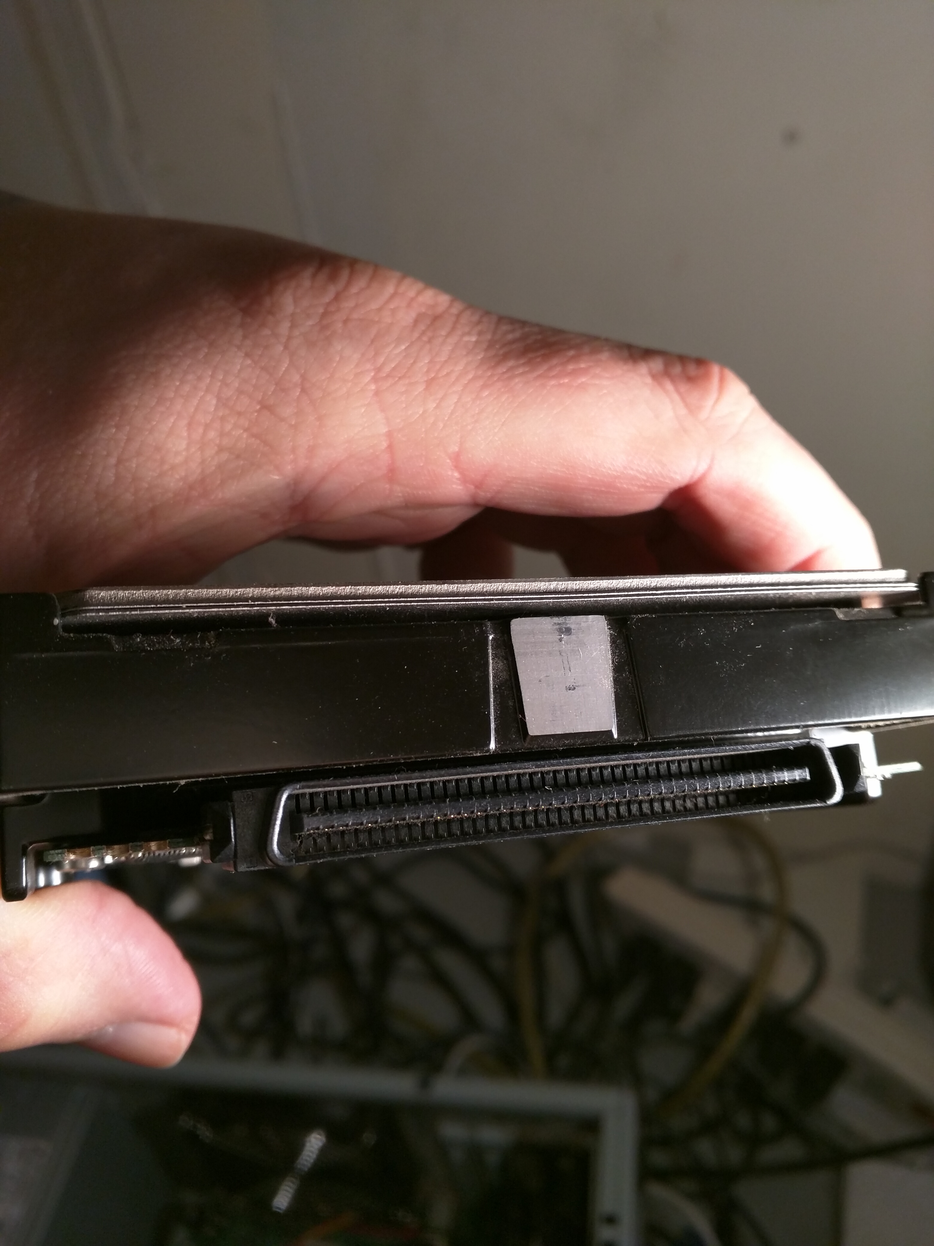 this is the drive and this;
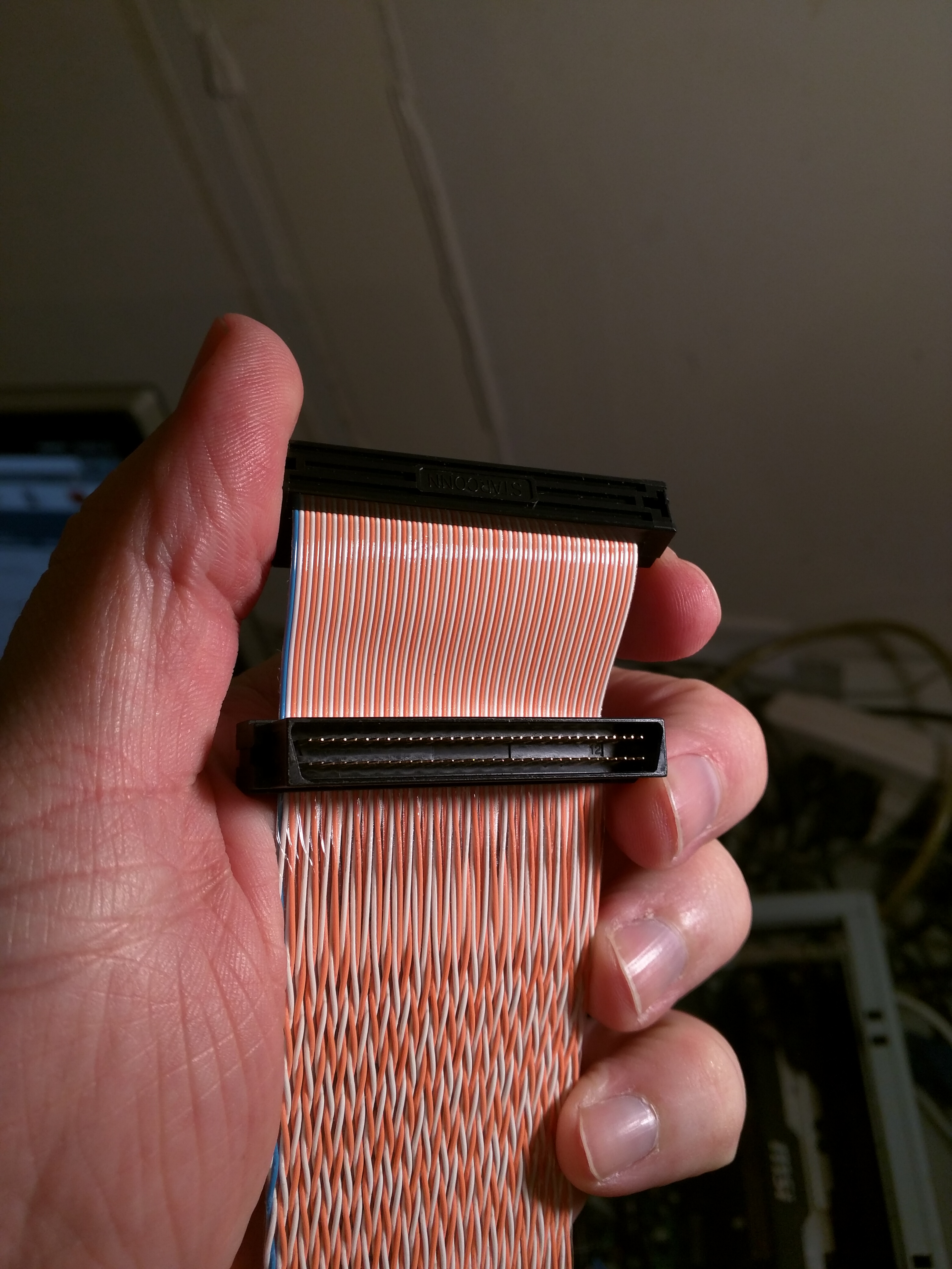
Is it an SCA 80-Pin HDD?
The cable looks to be a VHDCI 68-pin cable.
Correct on the drive, but I believe that is a 68-pin high density cable. Not a very high density.
2 Likes
Also note, if you are trying to use one of the SCSI drives as a bootable drive, you will have take the dip switches off of the drive in order to change that drive to a SCSI ID of 0. Boot drives should always have a SCSI ID of zero. (Note: Your host controller should be automatically assigned an ID of 7 in the SCSI chain.)
So glad I can finally use what I’m learning from my CompTIA A+ certification.
4 Likes
Yeah, it looks like the drive is a 80 pin and the cable + raid card is 68 pin. So it looks like I’ll need to buy adapters unless there is a cable that terminates in 80 pin but originates in 68 pin. Jeez, why? Ultra u320 should only mean one thing, just like sata 3 or ide.
Now you know why SCSI was never a product meant the average consumer, lol.
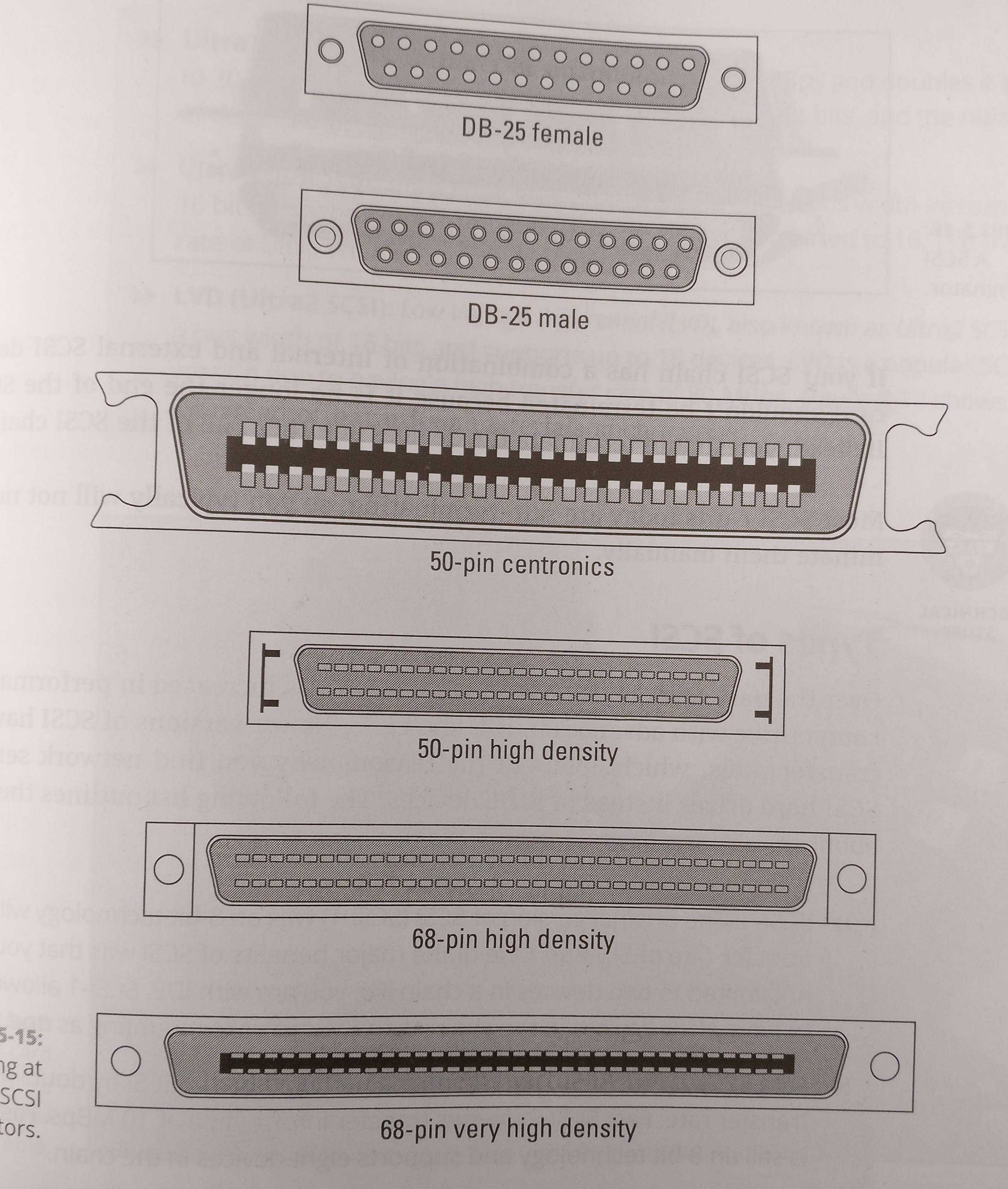
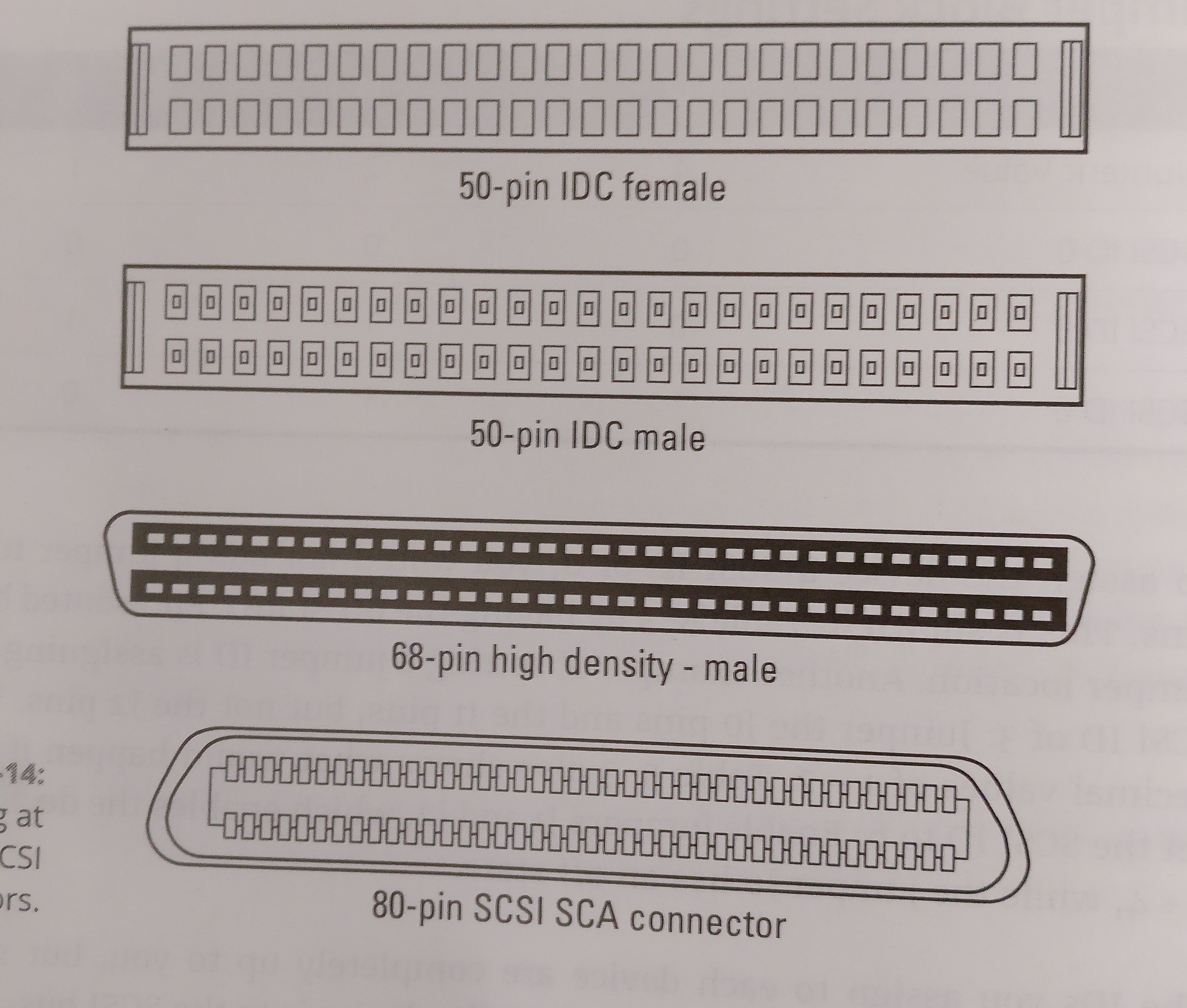
There were like 7 different standards for SCSI introduced over the years, in order to keep up with other storage technologies. Each revision usually used a different connector.
Paying attention to what SCSI revision the host controller and drives have is important.
2 Likes
I’m having trouble understanding if a 68-80 pin adapter will work with a boot drive in raid connected to a LSI Logic L3-00147-02C card on the pcie bus.
It’ll most likely work, SCSi 80pin was mostly used for hot-swapping drives (Data and power was in one connector).
I used it for a long time and worked without any trouble.
1 Like
I just realized that by the time I buy two 68-80 pin scsi adapters I’ll have hit about $40 in parts which I know is really nothing but funny b/c HP had $40 128gb SSD right now so I’m like… Well at least it’s fun to play PC Frankenstein in my basement on the weekends; can’t really put a price on that.
Yeah, that looks like the one I have.
I have a supermicro MB (X7SBL-LN2) that I plan to use with my drives and Xeon x3350 CPU. I noticed that the sim1u ipmi slot looks alot like a backwards pcie slot. Is there any interoperability there? Can that slot be repurposed for say a graphics card (i/o facing the wrong way not withstanding) ?
That is a PCI slot, not a PCI-E slot. There are no similarities or compatibility between the two. Do NOT try to fit a PCI-E card into a PCI slot. It will not work, and you run the possibility of damaging the card, the motherboard, or both.
The 2 PCI-E slots that you do have are ×8 and ×4. You will have to buy a ×8 to ×16 adapter in order to fit a standard graphics card.
Here’s the specs for the board.
http://www.supermicro.com/products/motherboard/Xeon3000/3200/X7SBL-LN2.cfm
Also, here’s how to tell what expansion slots you have, just by first glance.
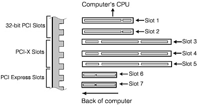
Wow, thanks. I thought I was pretty well versed on PCI vs PCIe. Just so I know we’re talking about the same thing here…My board 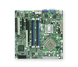
has 5 expansion slots, from left to right; A PCI slot (this is what I’ve always known as a standard PCI slot) next a x4 PCIe, then another 4x PCIe with a PCI slot directly behind it/within the same plane. Lastly, we have what the board manual labels a Sim1u ipmi slot, which looks suspiciously like a backwards PCIe. I see it’s orientation is like a PCI not PCIe, however it’s longer than a PCI slot by about a third. Approx the same size and dimensions as a x16 PCIe slot. Your diagram is a bit confusing. because it looks both the PCIe and PCI slots are identical save for length and orientation when there are also differences in connector width and height (me thinks) .
The PCI-E slots you have are ×8 sized. However, only one of them supports ×8 speeds, the other is limited to ×4 speeds.
That IPMI slot is a whole other can of worms.
This is the best explanation I found for it.
https://www.boston.co.uk/technical/2012/03/supermicro-ipmi-what-can-it-do-for-you.aspx
The TLDR is that it is Supermicro’s flavor of a Intel server management component, that allows for certain IPMI boards to be added. These boards add certain functions that can be found here
https://www.supermicro.com/solutions/IPMI.cfm
You will probably never use this feature, as most of it’s functionality is for large companies, data centers, etc. And in case you were wondering, it does not support graphics cards of any kind. Any graphics that come through that slot is from the on board graphics of the motherboard. That’s why you see supported resolutions in the specs from link above.
2 Likes