I've been working on photos for a basic guide on how to modify SFF 755 Dell Optiplex computers. I've got it down to well though out science. If i'm so lucky i'd like to post a video of my modded Dell Optiplex SFF 755 windows 7 steam box with all the cooling mods and what not. It's been running for a year and parts are cheap for these things and they can be found for cheap or free!
8 Likes
That would be cool to see
1 Like
Especially with those cooling mods
1 Like
I have NO business making videos. Sorry about that but, being pressed for time I made some videos.
Specs
Q8200S (Yorkfield) (65watt)
8GB 4x 2GB DDR2 800
128GB SSD
5TB HDD
ODD (DVD)
MSI GTX750 Ti Low Profile
Q35 Chipset
*** From what I remember when doing research at the time I remember the GTX 750 Ti Low Profile pulling 50 watts or less.
*** While the Q35 is Not compatible, Some 775 chipsets are compatible with the “771 Mod” especially if you can get modded bios.
EDIT: Looks like there may be a GTX 1050 Ti low profile!!!
https://www.overclock3d.net/news/gpu_displays/msi_reveals_a_low-profile_gtx_1050ti_gpu/1
ALSO: here is a little article about the Core2Quad S series & a list.
EDIT: The Q9505S can be had for about $20
- current video card. MSI GTX 750 Ti w/ duct tape.

EDITING***
Some insight on how it’s achieved.
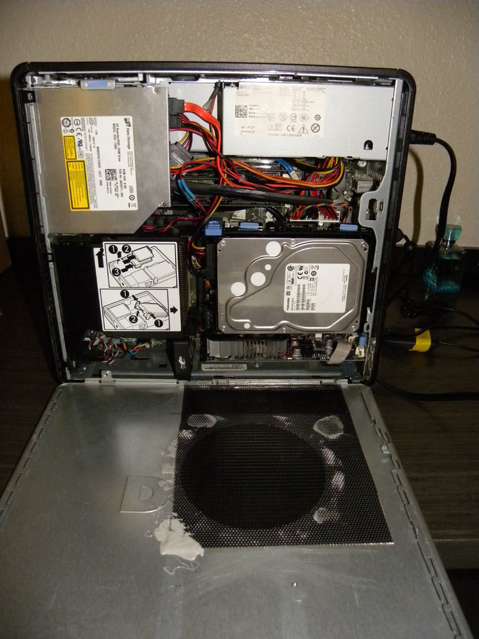
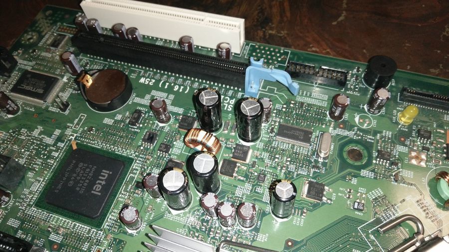
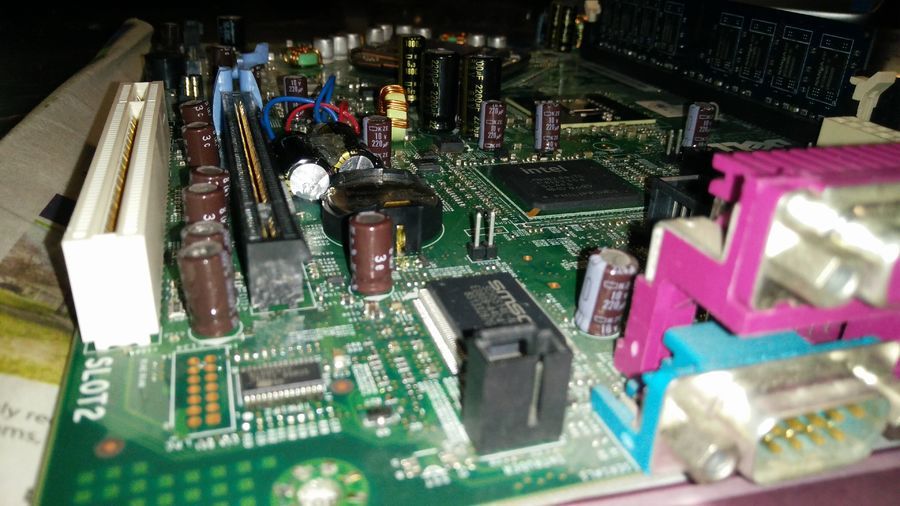
Here you can see the stock motherboard and you can see 2 distinct capacitors.
What are gonna do isn’t to hard it requires using a hot glue gun and BASIC soldering skills. I’m not saying it’s super easy if it’s your first time soldering but, it’s through soldering so it isn’t really hard if you basic soldering skills.
*** Do make sure the board is clean for the soldering and hot gluing. A cotton ball with some alcohol works great for where you are going to glue them.
First step is to remove the capacitor with out pulling ripping it off the board or pulling the leads out.
Second step is getting some small wire and soldering it to the cap. the trick here is a third hand to the the wire while solder it and hold it fora few seconds while the wire cools.
Dab a small bit of glue between the leads to help stiffen the wires after they are soldered on. keeps the wires from breaking back off when soldering the other end or when placing them on them on the motherboard.
The wire could be from a used IDE cord or some electronic device you took apart, or even the cables off an old dead fan.
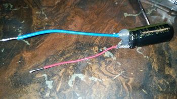
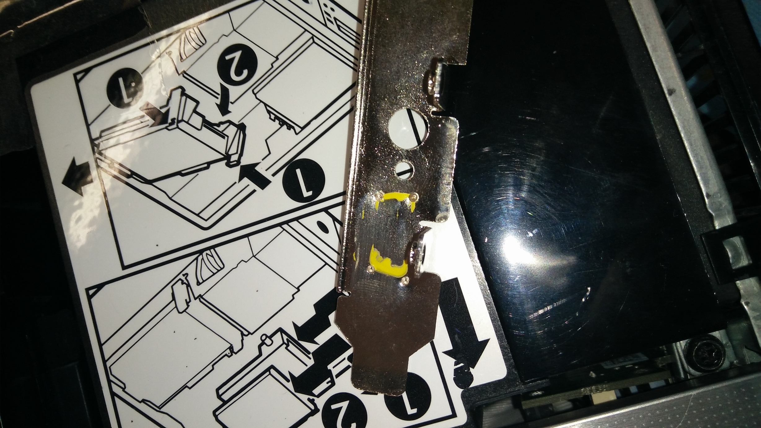
*** L@@K see the gold stripe! That is the negative side. The motherboard should have a thick white area underneath the negative side of the capacitor OR Vise-versa. If you look above at the first motherboard pic you can see the white arrow shapes under the NON negative side.
Simply use 2 colors wire or keep a close eye on which wire is what if you using same color and now you know what way they go back in.

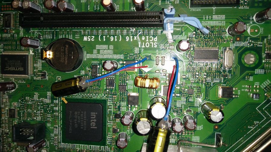
Third step is to solder the wires in to the motherboard where the capacitors were and the glue the capacitors with hot glue. Preferably higher temp hot glue but, it doesn’t matter. It also doesn’t matter what order you do that in, just remember to not solder the capacitors in backwards.
Positive to the white arrow and all the need now is a place to sit and another dab of hot glue.
A third dab of hot glue on the motherboard solder joints/connection. You don’t want them to break off when installing a card or other parts.
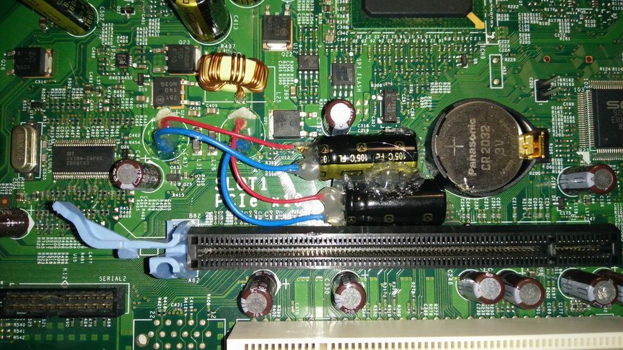
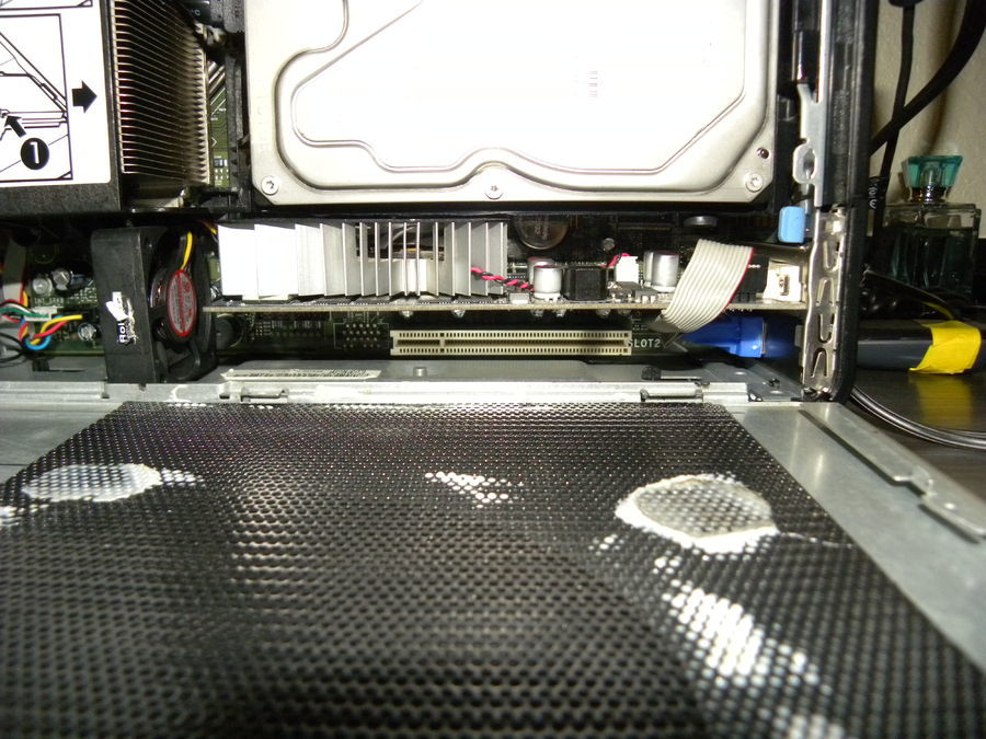
Well would ya look at that, it’s no taller than the PCIe slot and they aren’t going anywhere anytime soon.
*** If you plan on trying to overclock… Now is a good time to find out what a PLL is locate it on the board and get the number off the top of it. SetFSB requires you to know what model number your PLL is.
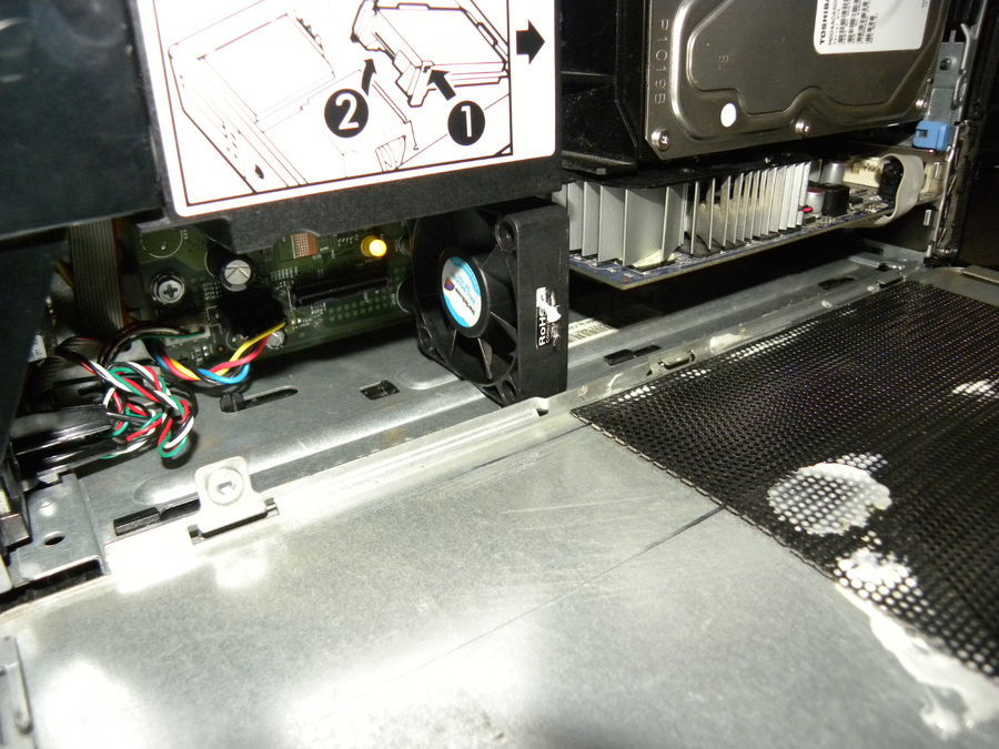
Now all you have to do is use a cutting or Grinding implement to shave down the side of the HDD caddy if you wish to keep it. If you don’t wish to keep it you have more room, maybe you could even install a 120mm fan as an exhaust or something?
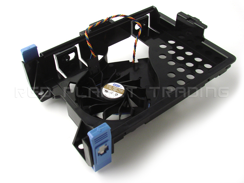
*** Keep in the mind the caddy has a fan in it for the chipset heat sink. I’ve grabbed some eBay photos to show you. The first pics has the latch with it but, i want to see the plastic ridge on the side that has to be removed. Also see how the fan is removable.

HA! Suck it bass ackwards form factor!
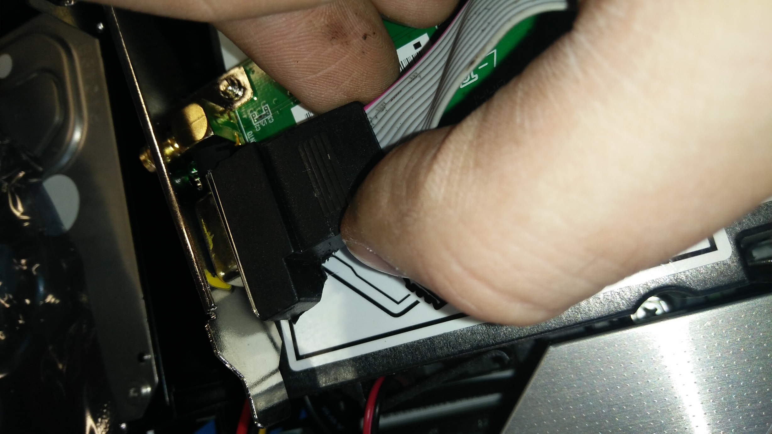
So the fan is just a cpu/blower fan out of random used laptop. In this case an old 2005-ish Toshiba.
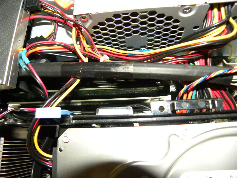
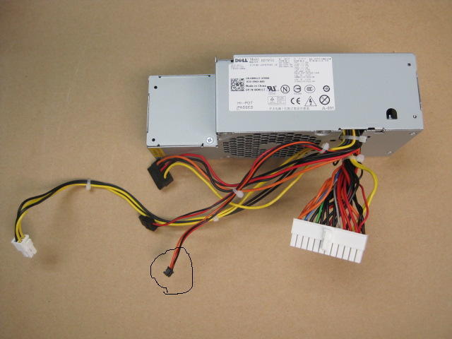
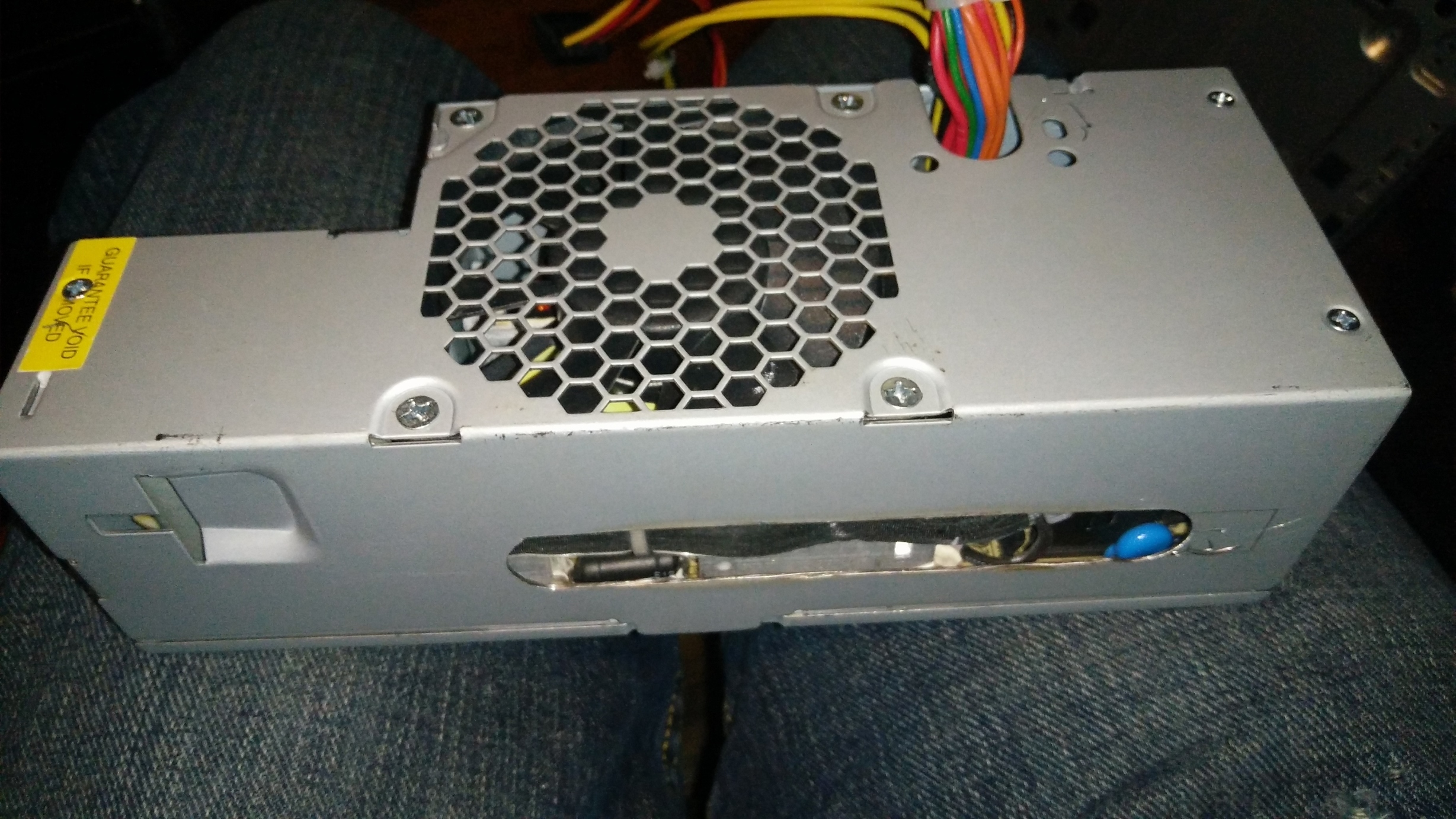
There a few things going on here. The main thing is power for the fan. my 755 SFF came this circled connector on the psu. The is connector is 2 sets of a positive and negative. Each of the 2 sets are different voltages. I used the lower voltage set and splice it in to the fan and hoped the fan wouldn’t fry.
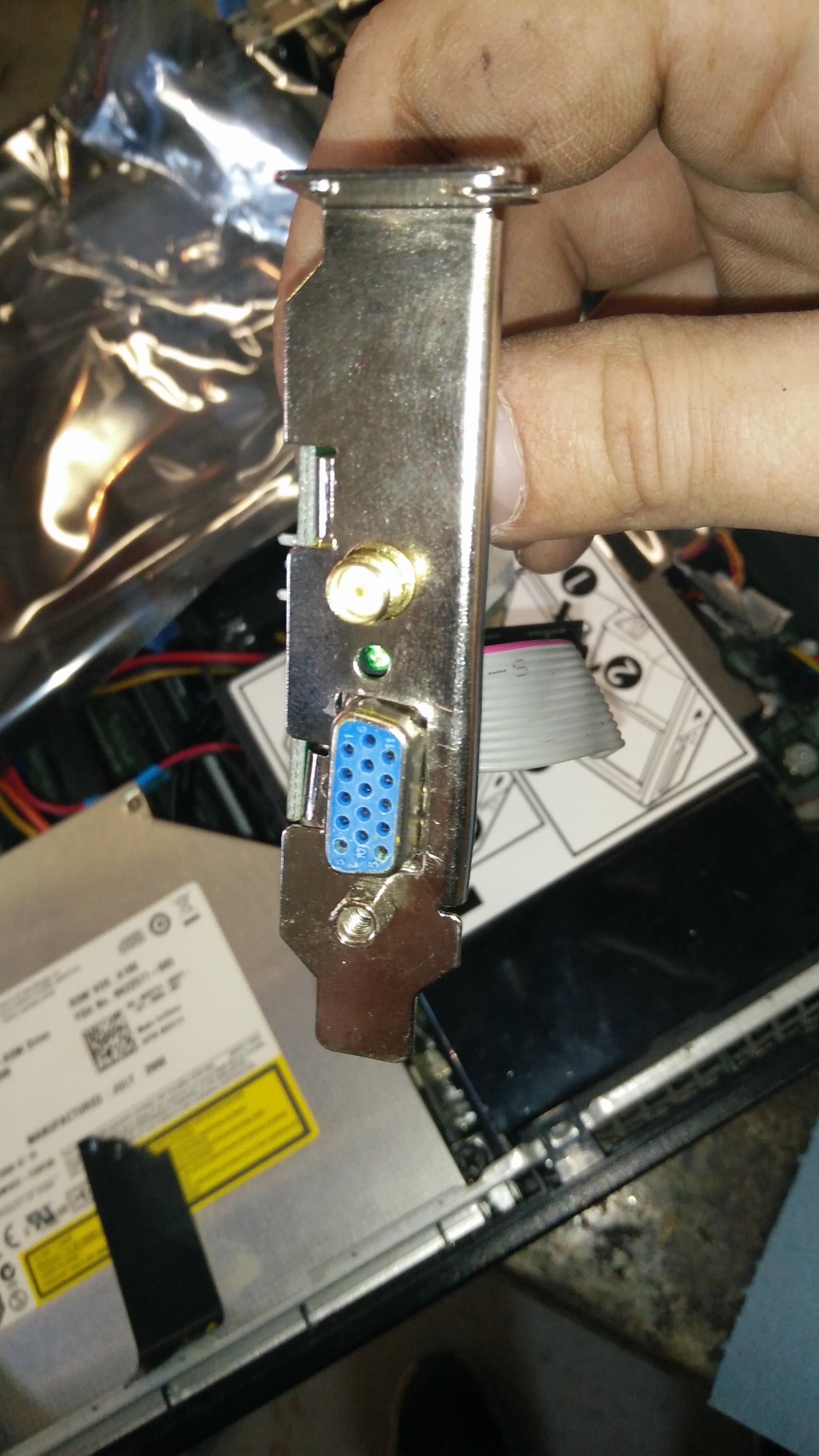
The video card is a dual slot MSI GTX 750 Ti low profile.
I took the shroud and fans off and the heat sink fins run in the right direction for a blower fan.
*** Blower fan voltage might be something to watch for.
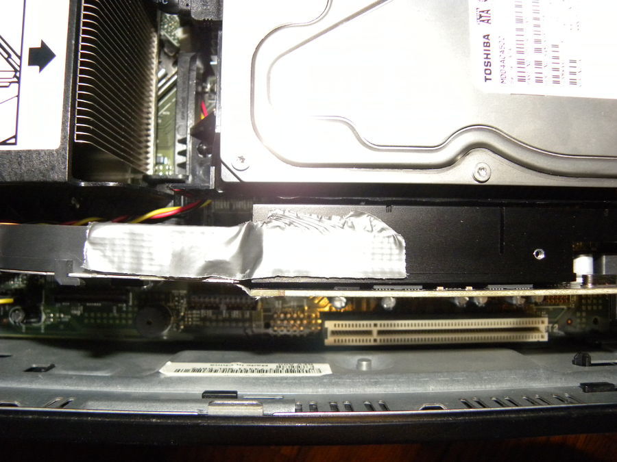
*** You can run tape over the fins to help direct the air form the blower and further insulate that air from the HDD.
If you’re PSU doesn’t have this connector that are other rails you can splice into. Alternatively if not using the HDD caddy nor it’s fan you could use that fan header to power a blower fan for the video card.
This also leads in to the PSU modding segment. They run hot and both of the ones i’ve modded so far have had the same 2 caps blown/leaking due to all the heat.
If you can do the above capacitor mod you can more than likely replace to the 2 bad caps should you have any. In my case I was in hurry so i only replaced 1 of 2 blown caps in both cases and they still work. If you replace ALL the bad caps and do the cooling mod it should be reliable enough.
*** I have not done any volt modding or any over clocking yet. Volt modding communities or forums with volt modding section like overlock.net or mod friendly forums like notebookreivew forums might be able to tell you where or how to do a volt mod. In most cases volt mods are basically the same as the capacitor mod except you attach a teeny tiny potentiometer instead. You could also do a research and see if the board is a candidate for a Poly mod, which is replacing stock capacitors with poly capacitors.
I usually ask for help with volt mods on forums but, here is another resource link.
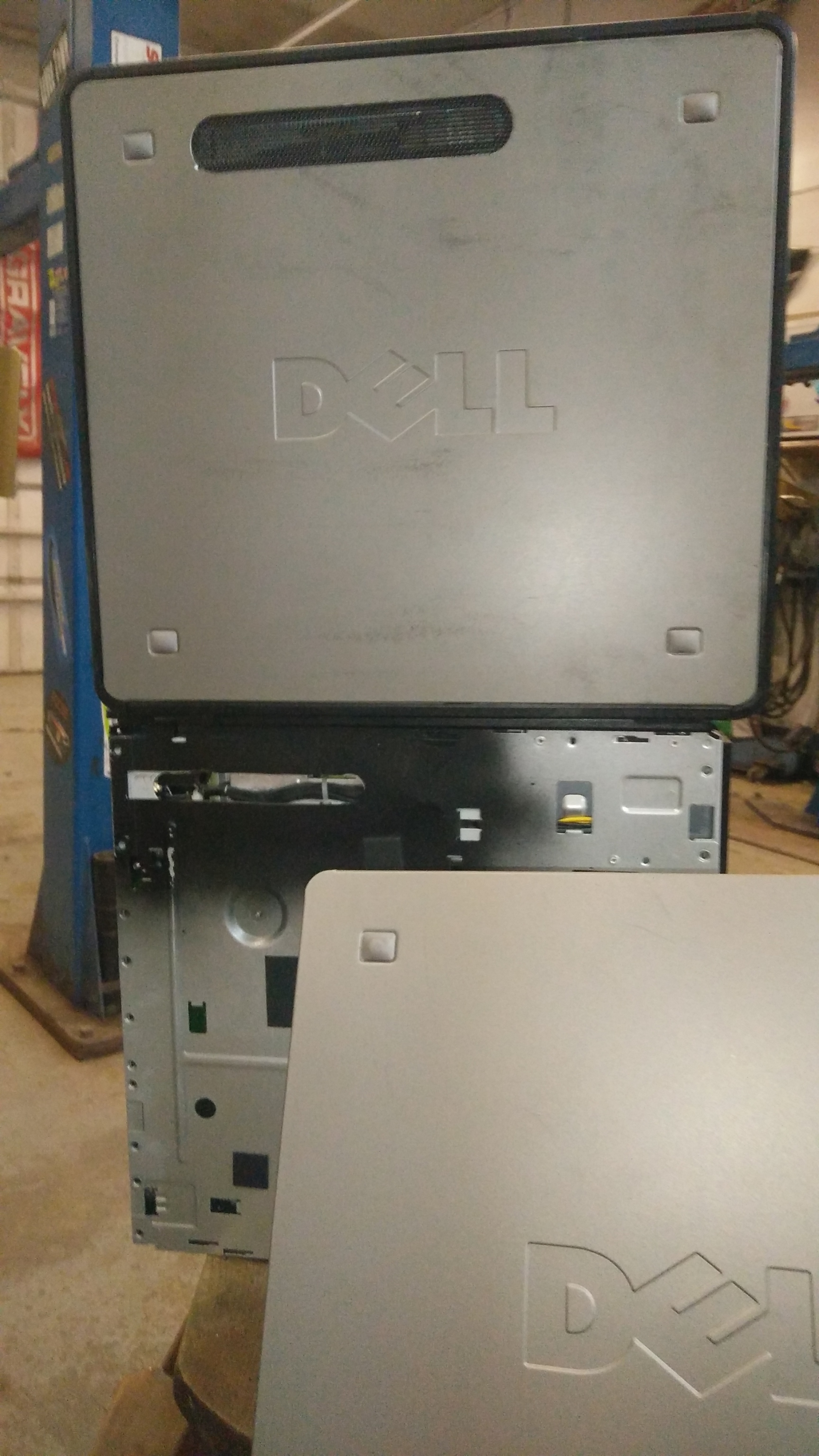
BACK ON TOPIC.
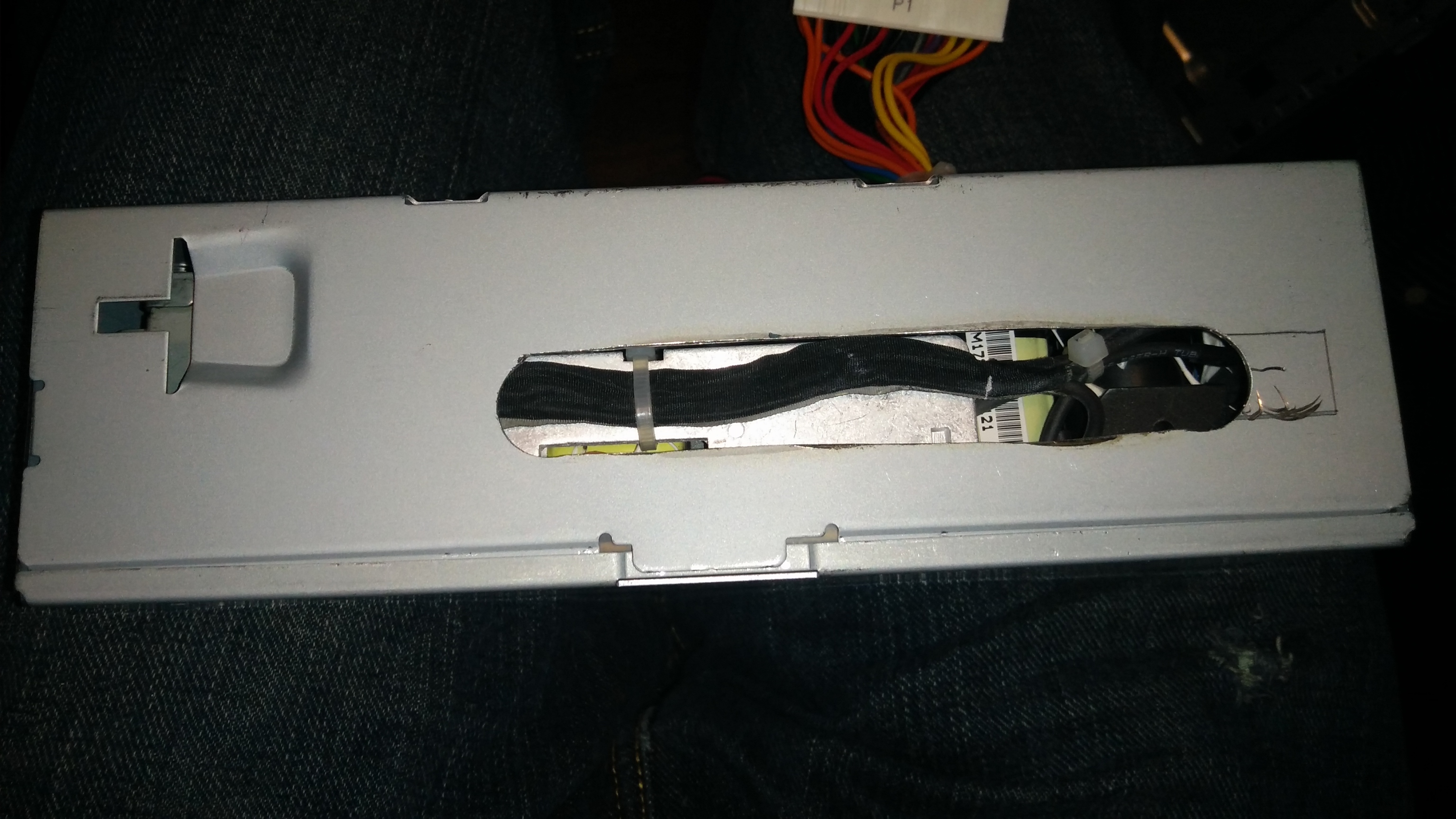
Disassembling the PSU is pretty much as easy as finding the screws and seeing how the case pulls apart. Another 4 or 5 screws and the circuit board comes out.
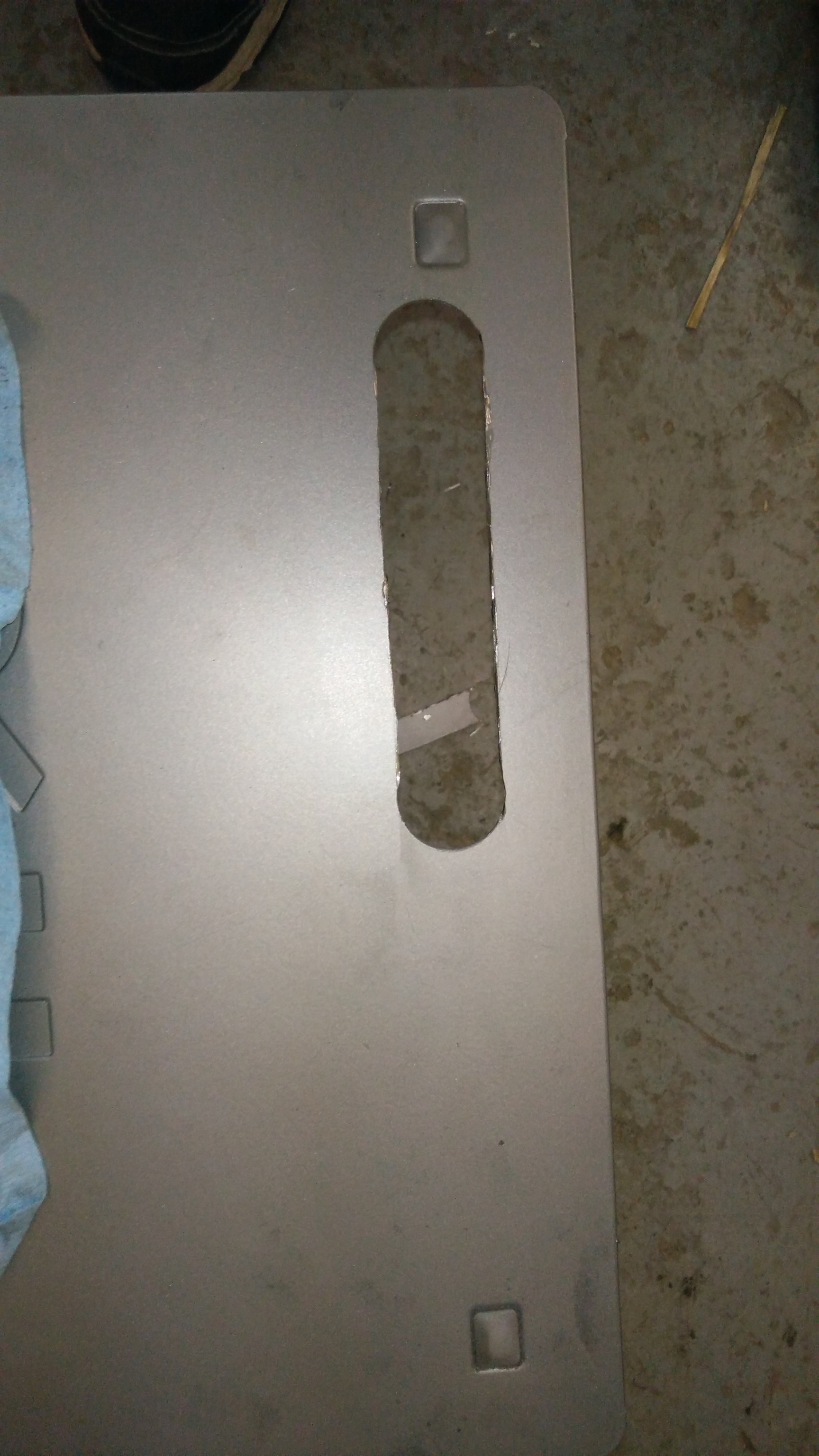
*** LISTEN UP! Here is where you can do a better job than i did. Instead of cutting a slit in the PSU case right away like i did. You can jump straight to cutting the outer case panel and then tracing the line on to the inner case and once it’s cut trace that line on to the PSU! Much easier, Measure once cut thrice!  Just Be sure to watch the size of the your PSU hole you don’t want it to be to big as you still want some of the air coming out the back of it!
 o
o
Here is probalby the hardest part, if you don’t have many tools you may want to go for a set of whole saws.
I borrowed this, I found it to be easy to use makes damn good cuts. Before Now I didn’t know these little buggers were a thing.
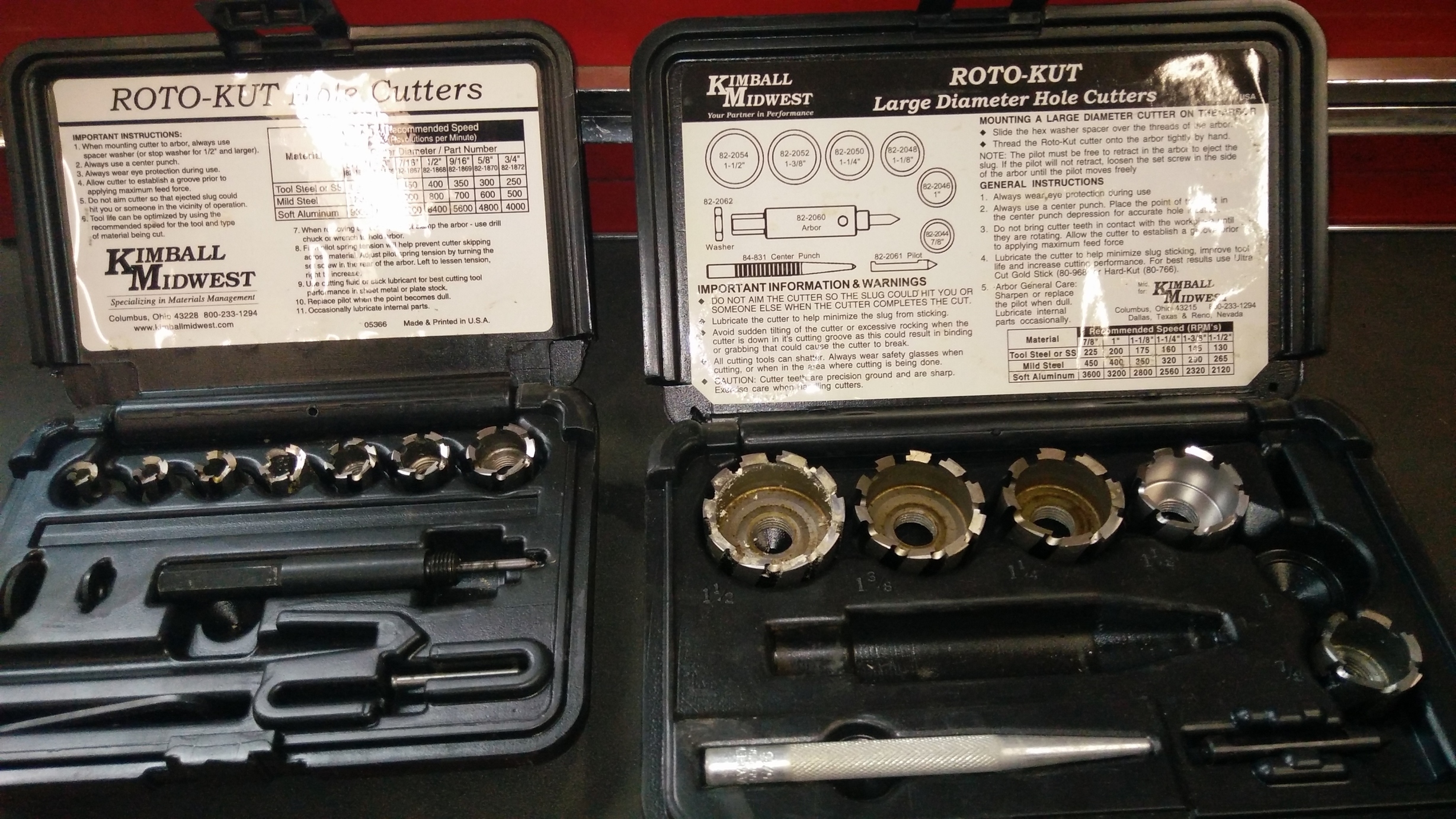
Drilling several hole and or using a Dremel would work too.
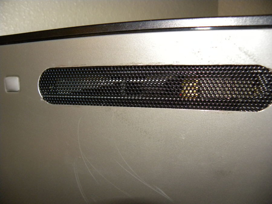
The top edge of the hole is about 1 inch from the top edge of the case. You can use that rubber foot as a reference point. I also suggest leaving to metal on the side of the foot so you have room to glue/epoxy the mesh and for rigidity when laying the case down and or transporting.
Tape Helps mark your line and also helps see better when cutting or grinding.
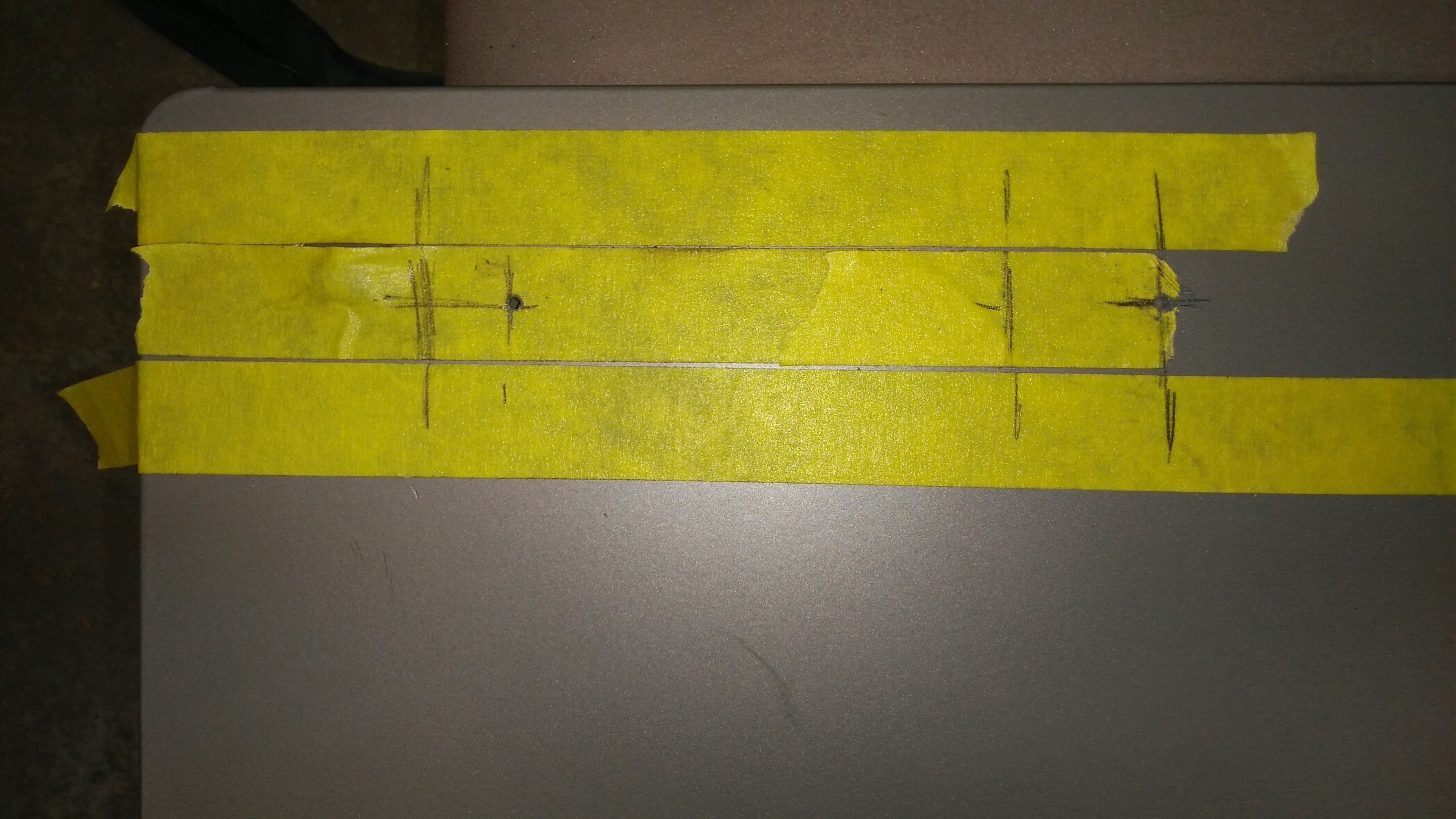
Once I had it measured and marked up, I drilled/cut my holes
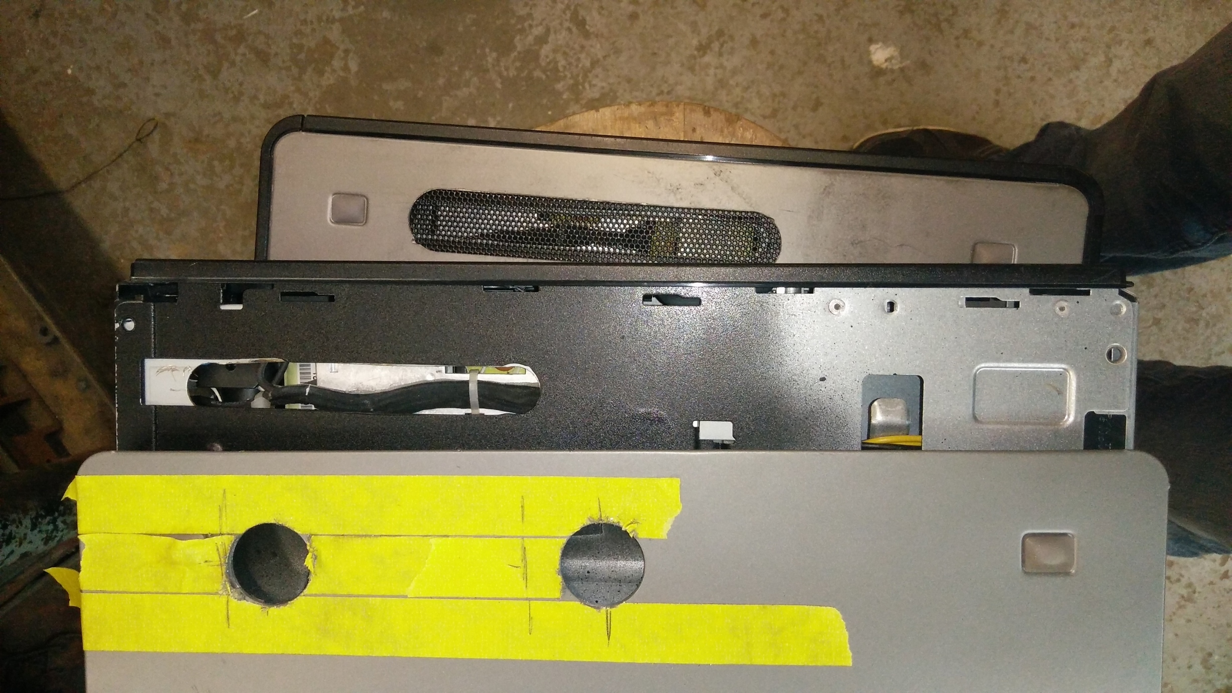
With the holes cut, I used tape to marl my line and a die grinder to cut out the rest.
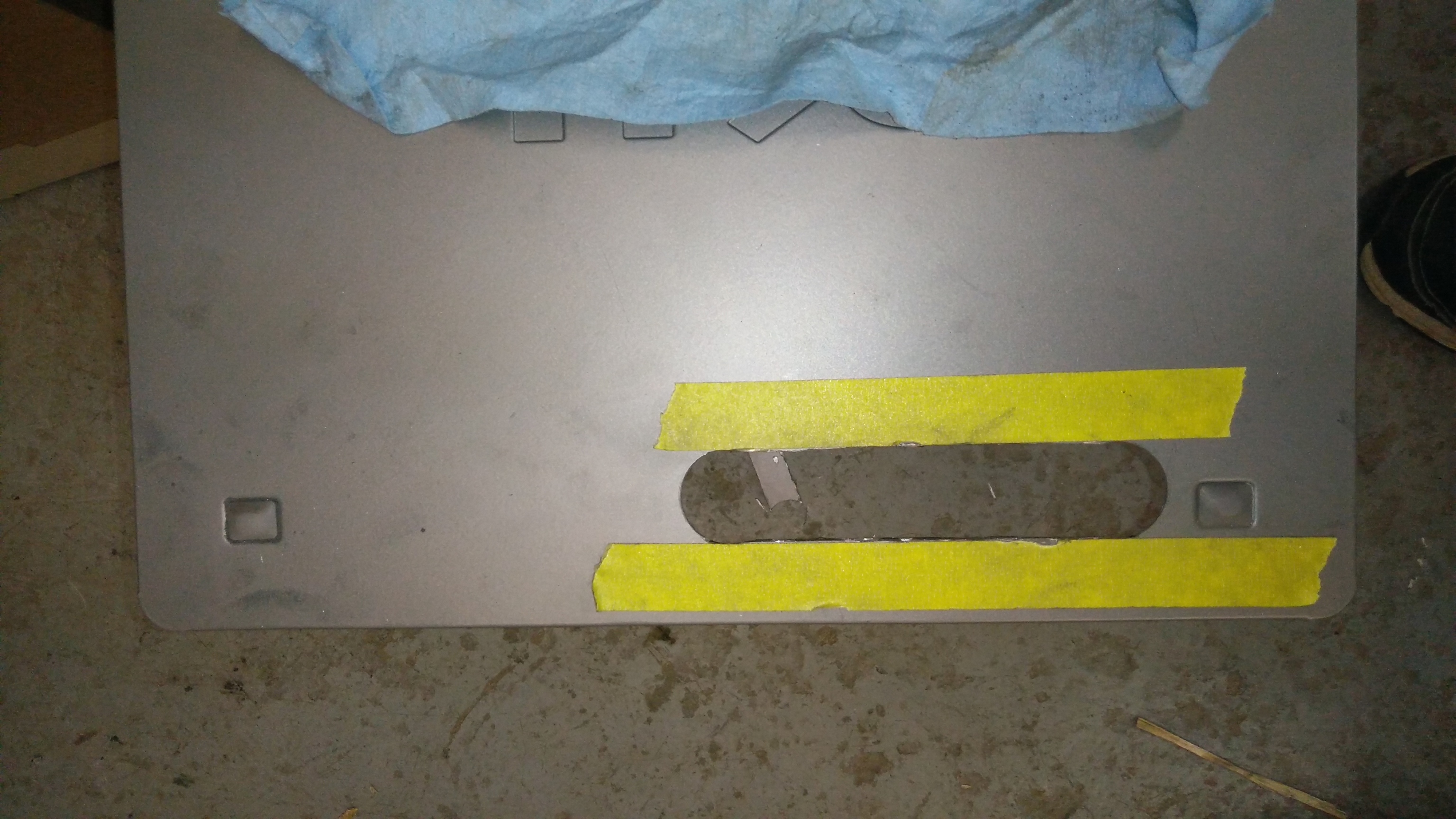
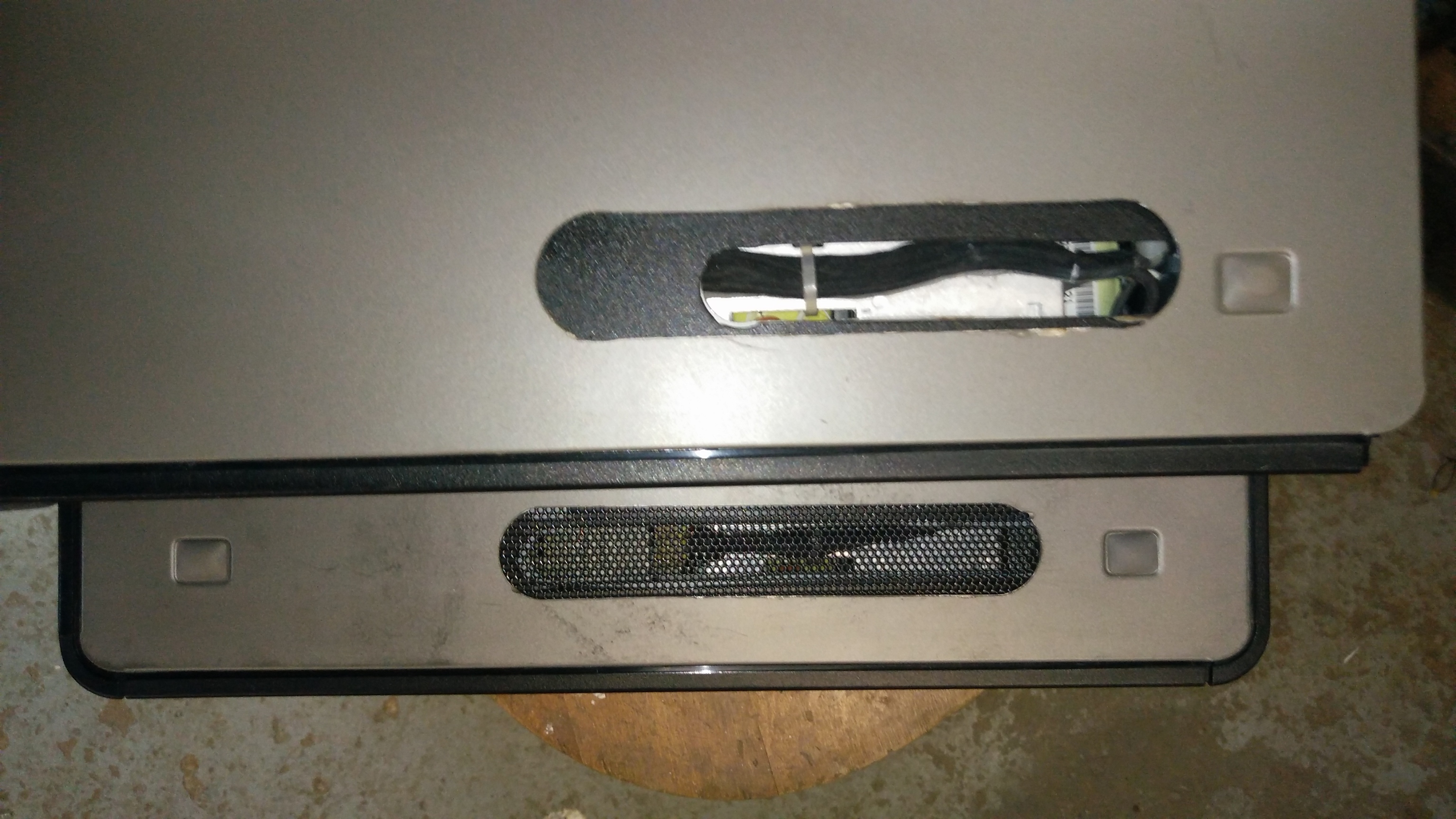
You ca trace the hole of the outside panel on to the inner case and cut it. You can re assemble the empty PSU case and install it to trace the line of the of the inner case’s hole and then cut the PSU case.
If you work from the outer case inwards to the PSU it can look a lot nicer than this.
*** Painting the inner case can help hide the “layers”. May not be necessary since I technically cut my layers backwards.

The removable panel cooling mod is pretty much the same stuff and you can mod that how you like. I might suggest a hole near the blower fan for it to pull colder air. Also slight near the video card to exhaust radiant heat.
For the mesh I put epoxy down around the the holes and then lay the mesh down. Clamps help but, OIL THEM DOWN FIRST! Other wise you’r case sides will also have a cool new clamp mod too.
Also one other word the Dell Optiplex 755 SFF can be overclocked with setFSB is you take the time photo graph your PLL or write down the PLL chip/model number. I have yet to try that though. Overclocking could be icing on the cake if you have a top model S series Core2Quad like the Q9550S. Volt modding and a poly mod could also help get a better bump on the FSB if either is possible.
I imagine any info on overclocking a non SFF 755 or 745 might pertinent to the 755 SFF.
FYI, NEVER EVER accidentally hit some random button on your keyboard your browser will wipe out all the info you have typed up for your guide. The resulting rage can cause harm the surrounding environment and it’s inhabitants.
9 Likes
This is the kind of getto hacks I like. Thanks for sharing
Would like a better videos, not that the videos are awful, but would be cool
Thanks for sharing. Using a blower fan for the graphics card is a clever idea.
That's a neat hack!
I would actually pay to see the facial expression of a PC technician who were to receive this as "broken" and asked to repair it.
Those capacitors man, hat's off...
1 Like
that is badass!!! NICE!
GTA V seems to run pretty smooth. i need to get some real numbers for benches/games.. I know builds like these work especially well with 4:3 CRTs and LCDs as well as odd resolution monitors like 1600x900 etc etc.
1 Like
Updated the main post with more information.
2 Likes
Looks like there may be a new low profile GTX 1050 Ti Low profile.
https://www.overclock3d.net/news/gpu_displays/msi_reveals_a_low-profile_gtx_1050ti_gpu/1
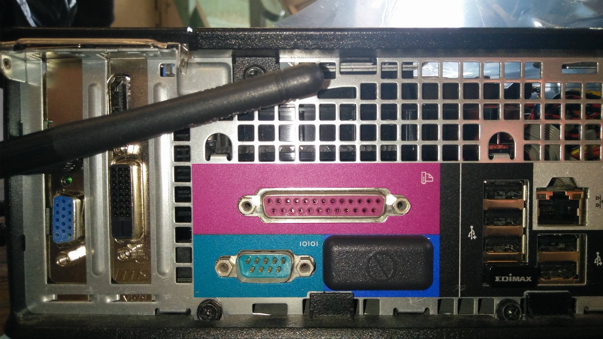
Got tired of USB wifi and not being able to download steam updates and watch youtube at the same time.

3 Likes
got an old crappy Optiplex 3010 for free and cleaned it up and jammed in a GTX 1050 and 6Gb of ram and a 480Gb SSD. $54 for the SSD and about $115 for a used GTX 1050Ti LP. Only modification needed was a piece of tape to keep the USB header cable out of the fans and a peice of double sided tape to stick the SSD where the disc drive went. also i have a a little ventilation where the disc drive face plate was (aka a speed hole)


What is gaming on 4 cores and a 750ti like nowadays? I have one of these laying around and a 960ti i could squeeze in.
1 Like
If you’re gaming 4 (core2 series) cores and a 750ti you’re probably gaming @ 720p (at least HTPC anyways) and to keep it short under 1080p seems ot work fine, never tried 1080 with the old setup.
a top end ddr3 core2quad with a big oc can pull 5k+ passamarks. the optiplex 310 has an i5-3470 which is 6715 passmarks stock! i need to play some games on this but, it should be decent! (haven’t played any games yet)
My living room htpc is a ryzen 5 1500 6 core with a 1050 ti LP and it plays doom 2016 at 4k!
EDIT: …and with the kick ass indie games on steam now… forgetta-bout-it even a core 2 duo is plenty for that!