Since I just finished successfully modded my own WYSE terminal keyboard, I'll show how to adapt one.
Bit of background: WYSE was/is a PC maker from the early 80's until the late 90's, at which point it was bought by Dell. For the most part, the PC's the made were so-so, and way less expensive than the competition. Most famously WYSE is known for Terminals. The keyboards that went with them all have Cherry MX Black switches (or are IBM Model M's).
Reason why you need to mod the keyboards to get them to work:
They use a propriety WYSE connector that is a 4P4C connection. Diagram is below:
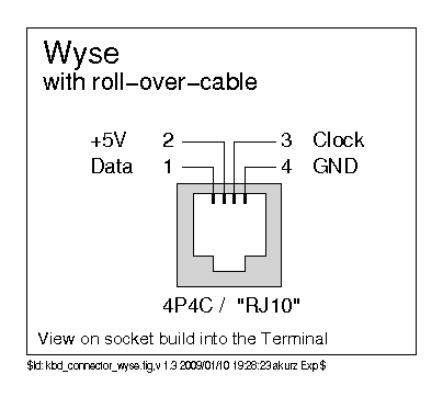
On WYSE keyboards, the colors are as follows:
Yellow is Data,
Green is VCC
Red/Pink is Clock
Black is ground.
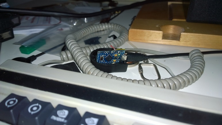
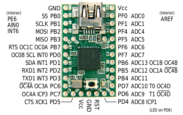
You will need an ATmega32U4 board, preferably the Teensy 2.0 (for ease of use). I used a Pro Micro, but the premise is the same. You'll need to connect the correct wires to these pins on the Teensy 2.0:
Data -> PD0
Clock -> PD1
+5V -> VCC
GND -> GND
After you have wired that up, you will need to set up your Teensy and load Soarer's Keyboard Firmware onto it. (link here: https://deskthority.net/workshop-f7/wyse-converter-t7424.html )
Credit to Soarer from Deskthority for some of the info, the pinouts and firmware are from his thread linked above.
After the firmware is loaded onto the Teensy, you'll be set to go!
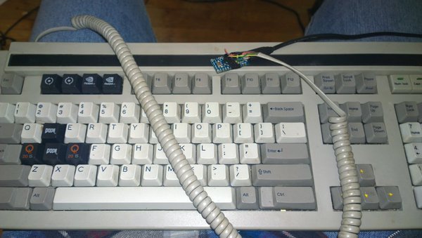
(heres a few pics of a finished one!)
2 Likes
Well, got done wiring the keyboard all up and also loaded the firmware but no input from the keys.
As you can see soarers shows up in my devices

Here is my wiring:
I tried the GND and VCC in both available spots
hmmm
also i found this:
TOPIC: KEYBOARD PINOUTS
DATE: 03/07/89
PRODUCT: WY60 WY99GT WY120 WY150 WY160 WY185 WY370
THE ISSUE:
Keyboard pinouts.
RESOLUTION:
WYSE 4 WIRE INTERFACE at the KEYBOARD CONNECTOR
                   1.   Data          YELLOW
                   2.   +5v           GREEN
                   3.   Clock         RED
                   4.   Grd           BLACK

    The keyboard wire is built with a half-twist.  Pin 1
    on the TERMINAL end of the cable is pin 4 on the
    keyboard end of the cable.
aka it might be switched for you, because the cable is twisted so that they are reversed on the ends of the cables. (i.e. the cable inside the keyboard will have a different layout than the one on the connector. Just need to flip what each cord does in that case.)
1 Like
also are the lights turning on or not?
Yeah, that pin-out diagram came with the teensy.
Will try the swap when I get back from work, and no, no lights on the keyboard. There is two from what I can tell the D6 and D7 but those might just be fuses.
There is no spot for lights to show up on the exterior of the keyboard unfortunately.
oh i forget that those dont have them... but yeah looks like is just reversed from what you have now.
so in your case
yellow is ground
black is data
green is clock
red is vcc
that should work, it is switching the 1 pin & 4 pin and the 2 pin & 3 pin around.
1 Like
Okay, after a good amount of time examining the pin out from the 4P4C connector confirmed that
Black -> Data -> PD0
Red -> +5V -> VCC
Green -> Clock -> PD1
Yellow -> GND -> GND
The reason why it is like this, is not because the cable is set to a half turn, its because the keyboard wires are wired directly to the Teensy, especially since I wanted the Teensy inside the keyboard enclosure and have the connector flush with the USB.
Aahhh, so excited that it is finally working.
Kind of want to redo the solder just in case and especially before hot gluing into place, well at least its not too hard to remove.
Doesn't look as pretty as some of the higher end factory soldering.
1 Like
le bump for those interested who may have missed it as it was unlisted for a long time lol