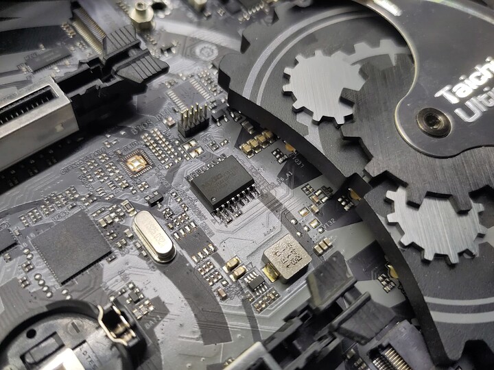
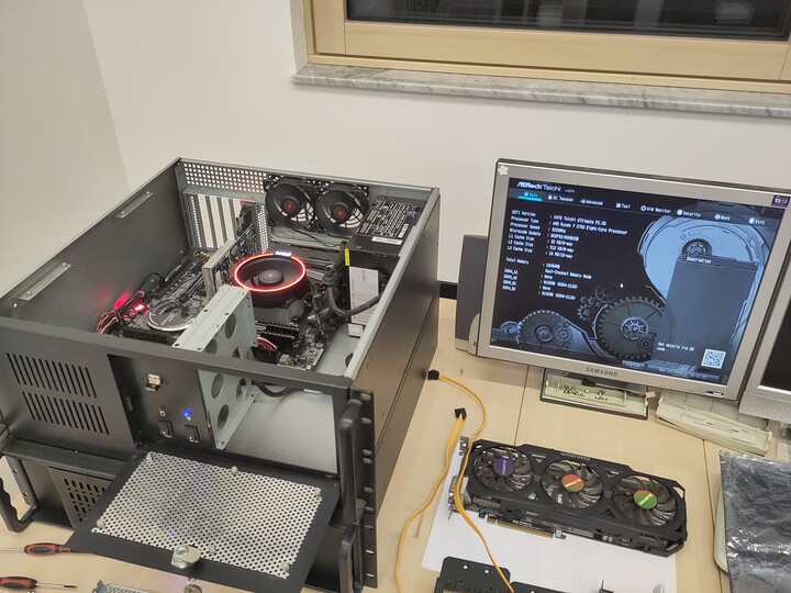
So, long story short, I bricked my motherboard (Asrock X470 Taichi Ultimate) trying to downgrade the BIOS to an older version (from 4.70 to 2.00).
Now I’m looking for some tips on recovering the bios.
I was following the steps described in this youtube video: https://www.youtube.com/watch?v=ZzqwjVDKAnU
I have successfully followed above steps once before, the difference being that previously I was downgrading form BIOS version 3.20 and this time I was downgrading from version 4.70, in both cases to version 2.00.
Things went wrong at the last step when flashing the BIOS, ending with the following lines:
...
Verifying NVRAM Block ....... done
Erasing NCB Block ........... 0x00000000 (0%)
43 - Error: Problem erasing flash.
I tried reverting to the previously installed version with no luck, so then i tried to flash the older BIOS again, resulting in the same error. A this point is said “Fuck it, lets see what happens” and proceeded to reset the board (probably should have left it running).
Now the board is stuck in a boot loop. The board powers up cycles trough some post codes, gets stuck at post code “79”, waits a bit then power cycles it self. For post code 79 the manual says “Chipset initialization error. Please press reset or clear CMOS.” and doing that has no effect.
At this point I’m pretty sure that I’ll need to manually flash the bios if I want to save the board, but I’m assuming that there is more to it than just grabbing the rom file from asrock web site and writing it to the chip bit by bit.
Thanks, Any advice will be appreciated.
UPDATE: I got it working again
Ok, so I managed to software brick my motherboard by way of a failed bios downgrade using AFUEFIX64 tool (Trying to get back to a version with working PCIe passtrough). This is how I was able to recover from this situation:
Since my motherboard (ASRock X470 Taichi Ultimate) doesn’t have any standalone BIOS recovery functionality (which should be a standard feauture on any reasonably speced motherboard) the recovery had to be done the hard way using an external programming tool.
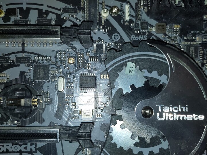
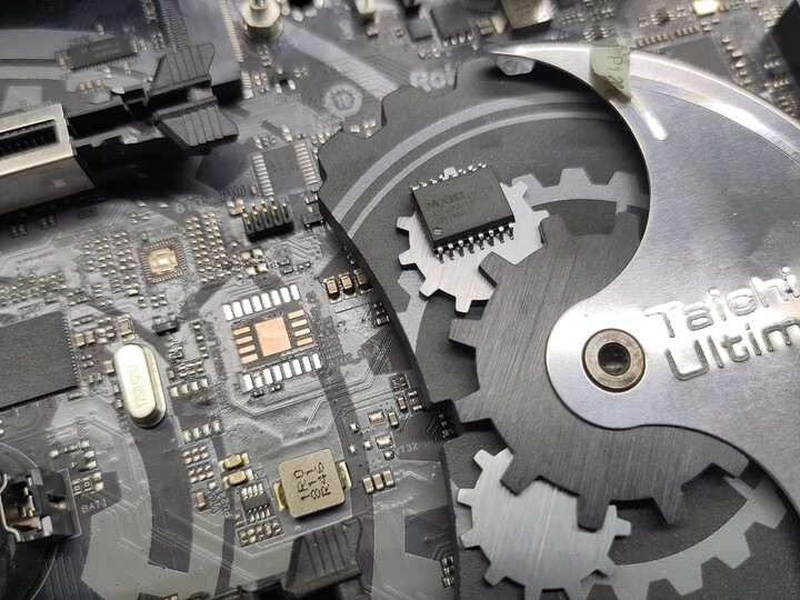
I started by locating and identifying the flash chip that stores the BIOS/UEFI firmware. In my case the flash chip is a MX25U25645GI00 which is a 32MiB, 1,8V part with SPI interface, in a reasonably DIY friendly SOP-16 package. Factory soldered to the board of course (If board vendors don’t want to include stand alone FW recovery functionality, at least they should put the flash chip in a socket).
Now I needed a way to talk to the chip. One very popular option is to use a CH341a USB porgramer and since the my flash chip is a 1,8V part, I would also need a voltage converter adapter to go along with the programmer. These programmers aren’t expensive at all, but I’d have to order it and wait for it to arrive.
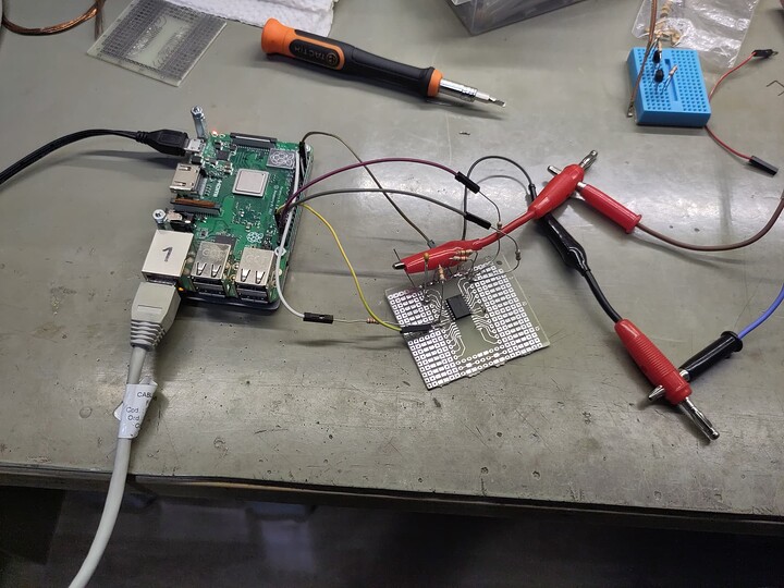
Instead I opted to use a RaspberryPi 3 running flashrom utility, which I already had on hand.
Now I could try to solder some fine wires to the chip while still mounted to the board. I found conflicting information weather the board should be on standby power or completely powered off and since I don’t know what other circuitry is present on those lines and how it would interact with my “programming tool”, I decided to just de solder the chip. This also made my future hack job flashing setup simpler to assemble and handle.
De soldering was done by first adding some good old leaded solder to the pins and then applying hot air while carefully trying to lift the chip with some tweezers without knocking over any other near by components. I had my hot air station set to 400°c and moderate air flow (so smaller components wouldn’t get blown away). After pulling the chip off, I cleaned the old solder from pads using some soldering flux and solder wick.
First I prepared the Pi by installing flashrom and enabling the SPI1 port by adding the following line in to /boot/config.txt:
dtoverlay=spi1-3cs
Then I powered off the RPi and proceeded to wire the flash chip to the Pis SPI1 port. Since RPi3 GPIO pins operate at 3,3V and the flash chip is a 1,8V part all signals that go from RPi to flash chip (CS, SCLK and MOSI) got connected trough simple resistor dividers (see below schematic) to bring the voltage levels down to something that won’t damage the 1,8V flash chip. The signal from flash chip to RPi (MISO) was wired directly (RPi3 specifications show the input logic high voltage threshold at 1,6V which is just low enough to accommodate the 1,8V output signals from flash chip).
Now that I had everything connected, I powered up everything and logged in to the Pi then ran the following command to see if flashrom can recognize the flash chip:
user@rpi3:~ $ sudo flashrom -p linux_spi:dev=/dev/spidev1.0,spispeed=1000
flashrom unknown on Linux 6.1.0-rpi6-rpi-v8 (aarch64)
flashrom is free software, get the source code at https://flashrom.org

Using clock_gettime for delay loops (clk_id: 1, resolution: 1ns).
Found Macronix flash chip "MX25U25635F" (32768 kB, SPI) on linux_spi.
Success, now to dump the existing corrupted flash image:
user@rpi3:~ $ sudo flashrom -p linux_spi:dev=/dev/spidev1.0,spispeed=1000 -r X470TU_fail_dump.rom
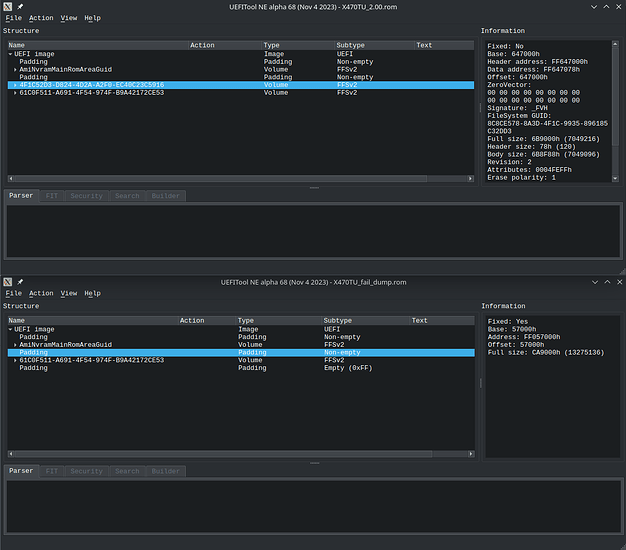
Now I was able to compare the corrupted flash image with a fresh image from ASRock using UEFITool, and one of the partitions (yes, apparently UEFI firmware has filesystems and partitions) was outright missing, its address space occupied by appropriately larger “Non-empty Padding”
There is also exactly 16MiB of “Empty (0xFF) Padding” at the end of the dumped corrupted flash image, so I also added the empty padding to the fresh image so that the flashrom wouldn’t complain about image and chip sizes not matching.
user@rpi3:~ $ sudo flashrom -p linux_spi:dev=/dev/spidev1.0,spispeed=1000 -w X470TU_2.00
...
Error: Image size (16777216 B) doesn't match the expected size (33554432 B)!
With the padded image ready, I could now write it to the flash:
user@rpi3:~ $ sudo flashrom -p linux_spi:dev=/dev/spidev1.0,spispeed=1000 -w X470TU_2.00_padded.rom
flashrom unknown on Linux 6.1.0-rpi6-rpi-v8 (aarch64)
flashrom is free software, get the source code at https://flashrom.org

Using clock_gettime for delay loops (clk_id: 1, resolution: 1ns).
Found Macronix flash chip "MX25U25635F" (32768 kB, SPI) on linux_spi.
===
This flash part has status UNTESTED for operations: WP
The test status of this chip may have been updated in the latest development
version of flashrom. If you are running the latest development version,
please email a report to [email protected] if any of the above operations
work correctly for you with this flash chip. Please include the flashrom log
file for all operations you tested (see the man page for details), and mention
which mainboard or programmer you tested in the subject line.
Thanks for your help!
Reading old flash chip contents... done.
Erasing and writing flash chip... Erase/write done.
Verifying flash... VERIFIED.
and just to be sure, I read back the freshly written flash and compared the resulting dumped image:
user@rpi3:~ $ sudo flashrom -p linux_spi:dev=/dev/spidev1.0,spispeed=1000 -r X470TU_2.00_afterflash.rom
flashrom unknown on Linux 6.1.0-rpi6-rpi-v8 (aarch64)
flashrom is free software, get the source code at https://flashrom.org

Using clock_gettime for delay loops (clk_id: 1, resolution: 1ns).
Found Macronix flash chip "MX25U25635F" (32768 kB, SPI) on linux_spi.
===
This flash part has status UNTESTED for operations: WP
The test status of this chip may have been updated in the latest development
version of flashrom. If you are running the latest development version,
please email a report to [email protected] if any of the above operations
work correctly for you with this flash chip. Please include the flashrom log
file for all operations you tested (see the man page for details), and mention
which mainboard or programmer you tested in the subject line.
Thanks for your help!
Reading flash... done.

user@rpi3:~ $ sha256sum X470TU_2.00_padded.rom X470TU_2.00_afterflash.rom
938f4ca31686422521efc81f9fe25bcccc3bea0afc8d874cec76f949974629ab  X470TU_2.00_padded.rom
938f4ca31686422521efc81f9fe25bcccc3bea0afc8d874cec76f949974629ab  X470TU_2.00_afterflash.rom
Next I powered off my RPi and bench power supply, retrieved the flash chip from my hack job flashing setup and proceeded to solder it back on the motherboard. Soldering was done using a small tipped soldering iron and flux core leaded solder. No additional flux was needed and what was left got cleaned using some isopropanol.
The moment of truth has come, time to power up the board and se if it posts.
Hell yes, ti does!
