Introduction
Finally, on the Level1Techs Store, is the Mstar Unicomp 2021 Mini M Controller Kit! This comes as the Controller Kit Only or we can pre-solder it for you. The Bluepill comes flashed with QMK- so don’t worry!
Please consider this a “Beta test” level of hardware shipping.
More info is in the installation guide written by Eric Raymond at
This is a how-to guide for anyone DIY-ing this!
What is it?
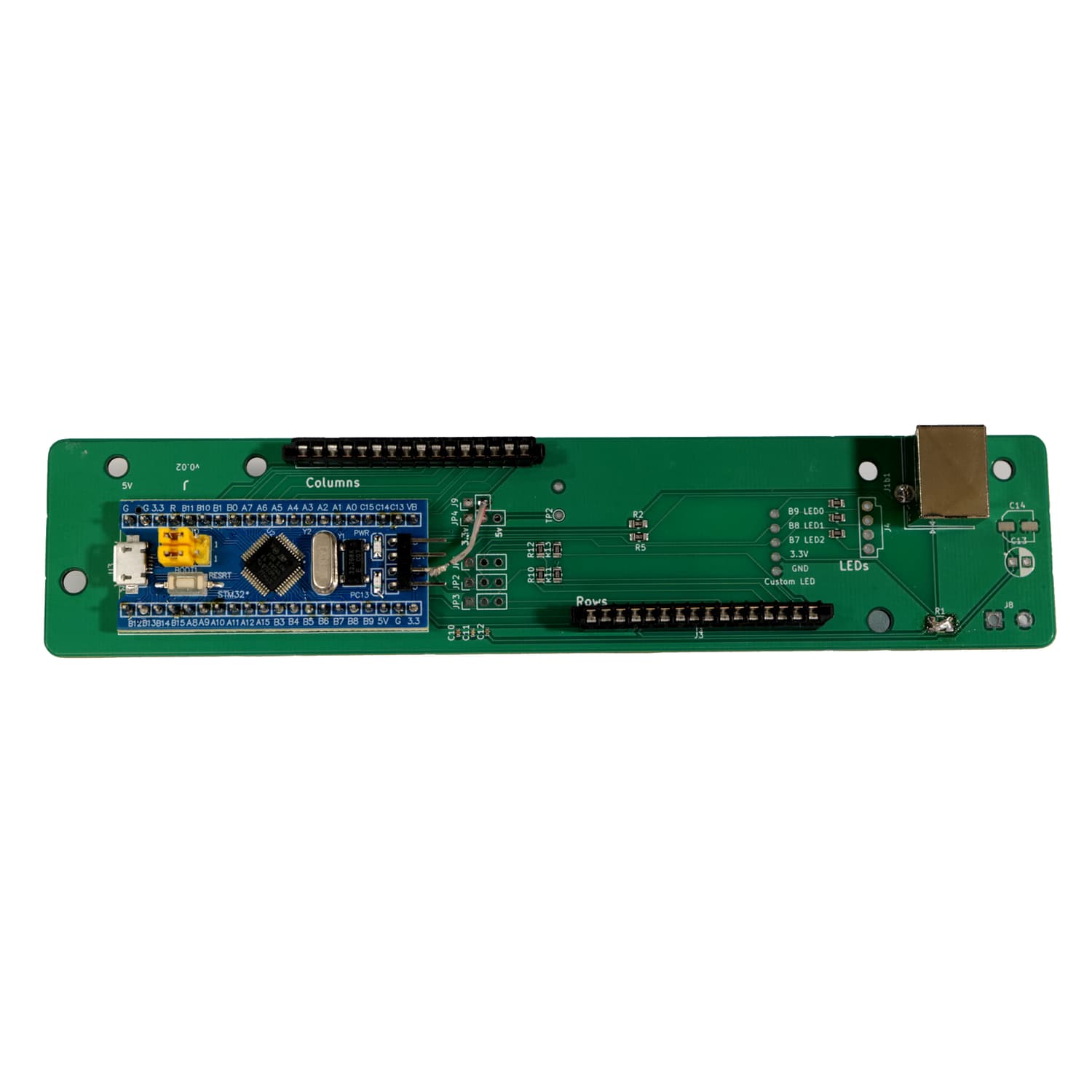
This product is a drop-in replacement controller PCB that’ll make your keyboard based on QMK and the STM32 micro.
If you purchase a “Controller Kit Only” kit you will have to solder the board yourself with the given components.

Resources
For more information, we have several supplemental sources. If you’re confused or want some general information about what you’ve just bought, here’s what we have!
Original Idea Video:

Keyboard Article:
GitLab project:
Before You Begin
For this DIY, you will need:
- Mini M Controller Kit
- Soldering iron + flux
- USB A to USB B cable
- Bendable metal (e.g. a paperclip, bread tie, repurposed wire)
Generally I would recommend that this is not your first electronics project, and that you have some experience soldering if you order the soldering kit.
If you order the pre-soldered kit, it is a drop-in replacement for the controller.
Step 0 - Prep your Unicomp Mini M
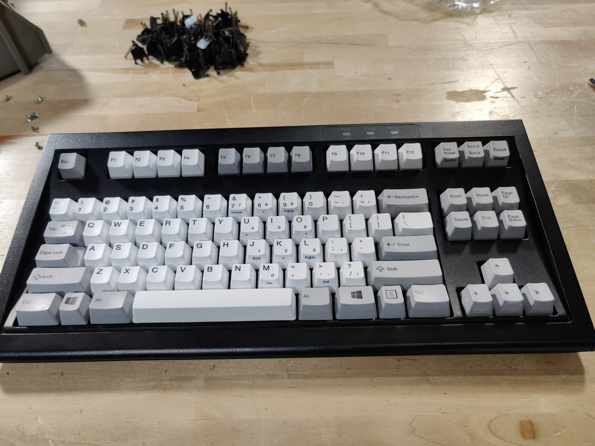
You should only need a Pozidrive screwdriver to take apart the mini-m. The built-in controller is held in place with some friction washers on plastic pegs.
Once the screws are out be very careful. If the keyboard falls apart it is likely to be very hard on the flexible plastic membrane connectors that connect the actual board of keys to the Unicomp Mini-m controller board.
Carefully flip the keyboard right side up, lift the back of the top plastic case up and it should unsnap at the front.
Pay attention to the feel of this disassembly move as you will repeat it in reverse to reassemble.
Carefully lift the keyboard at the back a few mm to lift it off the pegs at the rear and then slide the keyboard so the catches at the front of the bottom of the keyboard case no longer catch the board that actually has all the keys on it.
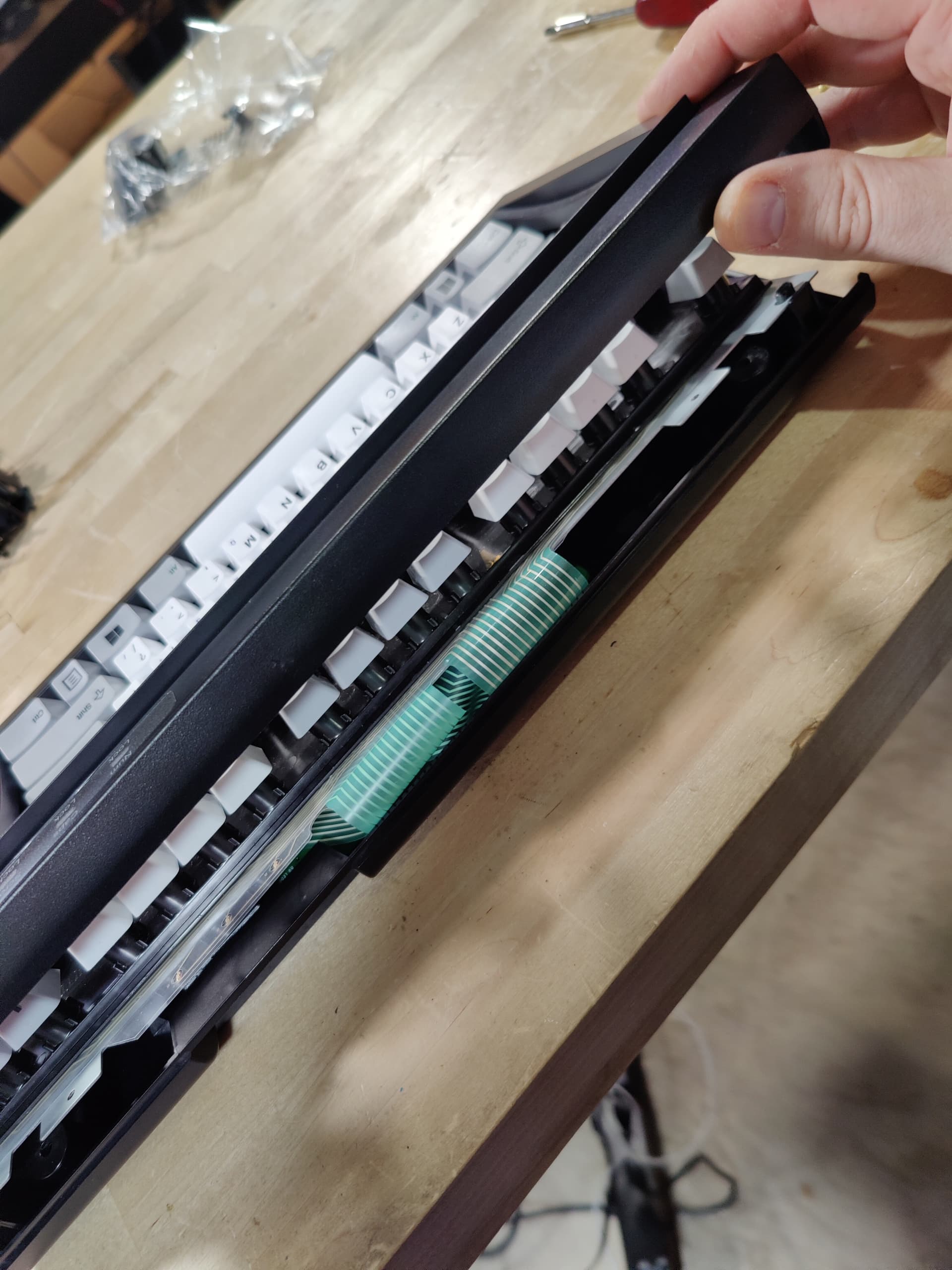
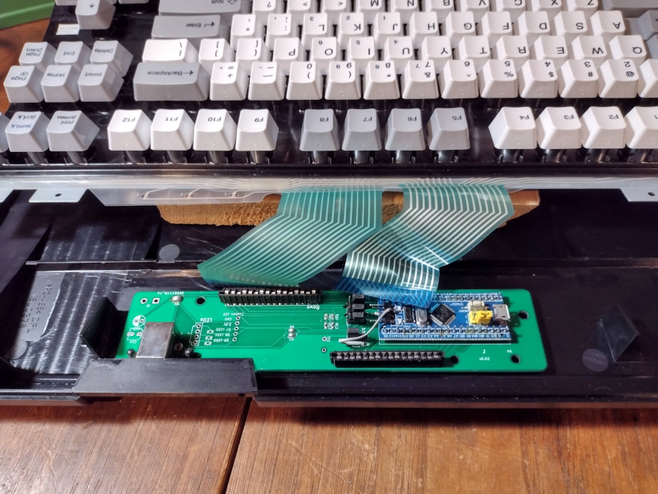
Carefully move the keyboard toward you without putting strain on the flexible ribbon cables.
Removing these ribbon cables without damaging them is tricky. They’re rated for something like 10-25 insertions +/- so keep that in mind for this next part.
Punch the ribbon carefully and pull the ribbon straight up. Again, pay attention to the feel as you will repeat this motion in reverse when installing the new controller.
With the board of keys disconnected from the controller, it is time to remove the controller.
It is held in with two friction washers.
Removing those is a bit fiddly, but doable with common hand tools such as a small flathead screwdriver, pliers, etc. If you prefer it is possible to use side cutters to quickly remove them.
There is also an optional 3d-printable plastic shroud that will help hold the PCB down if you’re worried about it.
Removing the ribbon cables requires care
Begin heating your soldering iron and gathering your pieces. We recommend a temperature of around 670 degrees Fahrenheit. To solder them onto the board you will need to place the parts in their respective through-pins, and solder the backside.
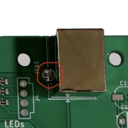
Step 1 - USB type B Connector
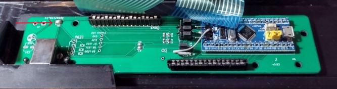
The power connector has little prongs to help hold it in place once for your first solder. It is also going to require the most solder. The important part is to make sure you put enough solder on the back to make a small bubble on the top side (circled in red).
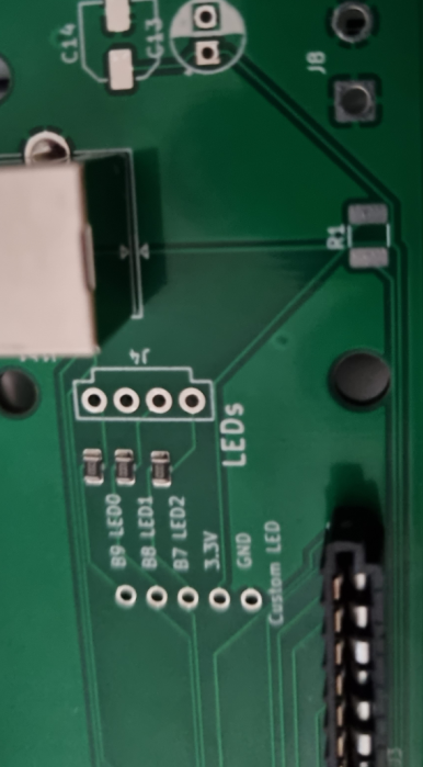
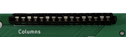
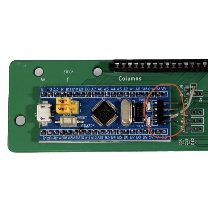
Step 2 - 16-pin Connectors
To solder the 16-pin connectors, it’s pretty straight forward, however you will need to make sure the connectors are correct-side-up on the PCB. The silk screen matches the connectors shape.
The connectors have a long top and the bottom is shorter. The long tops would be facing each other on the board.
In the picture below, the long top is facing inward to the word “Columns”
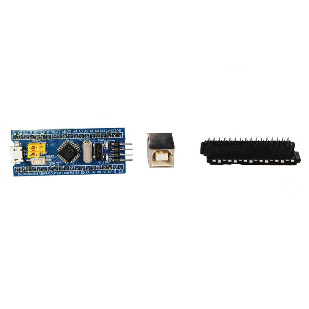
Step 3 - Bluepill
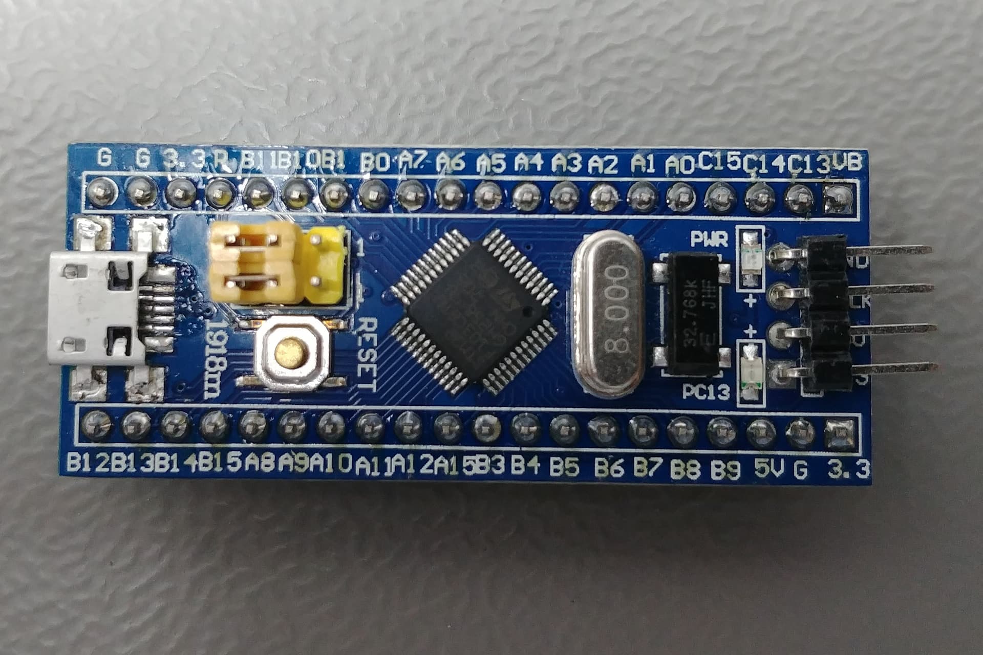
More information about the Bluepill here:
Important: When you solder this item to the board, make sure the 4 pronged end is pointing inward on the board.
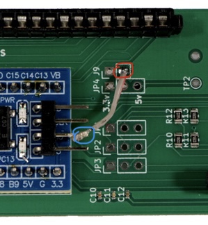
Step 4 - Metal Connector
NOTE: The soldering iron will make the metal connector very hot! Place the metal, then solder it in place, rather than holding it while soldering.
For this final solder, you’re going to want to use the piece of bendable metal mentioned in the “before you begin” section. A paper clip will do just fine.
When looking at the Bluepill soldered on the board, the Bluepill has 4 right angle pins. You’re going to want to solder:
(From top-down) Solder the metal to the 3rd of the 4 right angle pins (marked in blue).
TO
the 2nd through-pin in the J9 jumper (marked in red)
Done soldering!
The controller comes preflashed ready for you to load the QMK on it.

See here for more info about customizing QMK.
As this is a beta test run please comment here with anything you run into so we can incorporate that into the full release, soon, hopefully