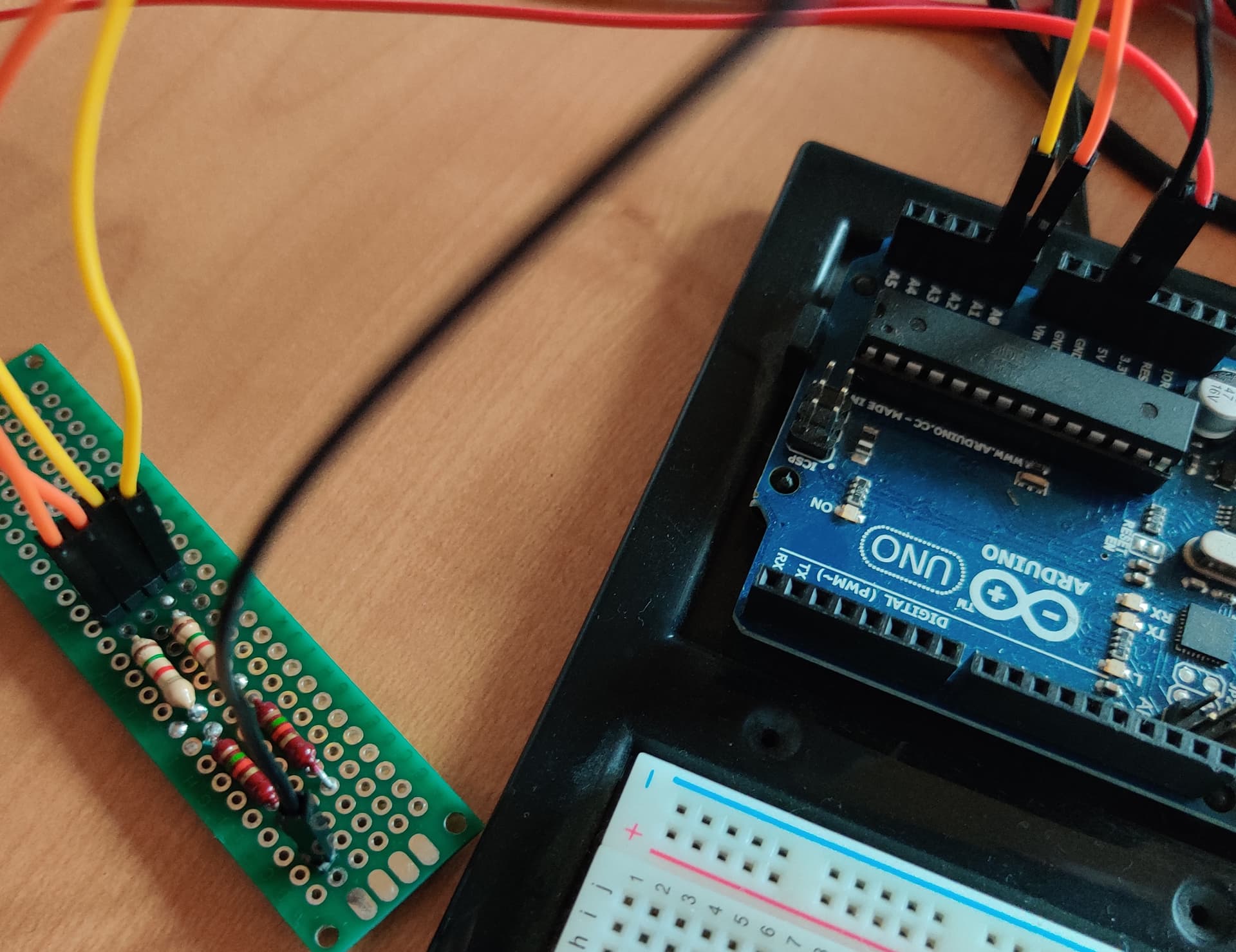
I’m currently trying to realize a button (normal home light switch with long wires) using the analog inputs of an Arduino (need an analog input because of noise, I’m trying to filter it, but the PI digital in seems to be too sensitive). I’ve got it up-and-running to do the actual detection, but I’m now at a point where I’d need a constant stream of information from the Arduino to the daemon. The daemon is running on a Linux platform an using the USB serial connection.
The problem is that with a serial connection the daemon might jump on the connection at any time because there’s no frames and the daemon can connect at any time. This basically invalidates most of the recommendations about using length-delimited framing. So what I’d need is some kind framing using delimiters and escaping. What came to my mind was Modbus over serial, but the problem is that I’m in an no-std environment, so there isn’t really any implementation and I don’t feel comfortable enough implementing that myself.
Yes, I probably could use C but I’m trying to avoid it. Also I could probably use some kind of shield on a PI, but I kinda didn’t find anything good, especially something that has more than one analog input and has solid support in rust (or is simple enough to port over).
Does anyone have any suggestions on protocols/libraries/techniques I could use to solve that problem? I figured if I want to find someone, who knows stuff like this, then it’s here.
So, you’re trying to sense the state of a light switch using an arduino, and then read that state from a pi connected to the arduino via a usb serial interface. Is that correct?
And you’d like to have a daemon (preferably written in Rust) running on a linux host that (reliably) gets notified of light switch state changes. Is that correct?
One way to achieve this would be to load a special Arduino sketch called Firmata that implements a standard interface over the serial host connection to the various Arduino pins. You can then hook a Rust Firmata client (your daemon) to the serial interface. This saves you having to write any serial communication code yourself.
Yes that is basically what I’m trying to do. The linux host with the daemon will be a PI in the end, but I’ll try to keep it generalized as I’ll pack it into an OpenHAB bridge.
Firmata does actually look quite good, I’ll check that out. It does mean that I’ll have to use C on the Arduino (although there seems to be some standard firmware that might work fine), but I was kinda prepared for that, given that rust on Arduino ecosystem support isn’t really mature.
Is it a home project intended for your personal development, or is it intended to be running in a ‘production’ environment (e.g. other people other than you depending on the thing to work)?
If you need ‘production’ ready reliability you may well be off with something that already provides the framework for coordinating communication and I/O between the arduino and external entities (openhab, mqtt, homeassistant) like Souliss : (http://souliss.net/)
If your aim is to get comfortable writing software to interface with Arduino and Homeassistant, then I have a question:
why would you want to send a ‘stream’ of data to handle a button press ? Do you mean to implement the ‘button is pressed’ logic in the daemon? If so, I don’t think it’s a good idea, as the serial link will be way too slow to implement a sensible poll rate, and to be able to do debouncing …
It’s basically a home project. If I’d use it in a more “production” environment, I’d probably fetch a microcontroller or arm barebones and add the sensors directly to it, but I try to do it with more or less of the shelf hardware that’s not too expensive, communication that doesn’t leave my home, is encypted (and authenticated), and is wired and I don’t want to spend a few years developing it. But I do of course take any “free” (/ cheap) reliability improvements. I try to avoid wireless though and I don’t really have a port left on my switch without getting a new one.
I’ve checked the serial speed, by just printing the value and I wasn’t fast enough to not have multiple values written while the circuit is closed, so it should be fine. If you know some 3.3V I²C (or SPI) board with analog inputs or digital inputs with a voltage threshold (because of the noise generated by ~8m of wires that aren’t as separated from the 230V lines as they should be and a motor on the grid in that room that seems to cause voltage drops) I’d be glad to consider it because the Arduino is just acting as a glorified analog sensor in this case.
Hmm, I would go with a RS485/Modbus solution then, with a small local module like this:
and only the rs485/Modbus communication going over the 8m of distance, possibly using twisted pair cable to reduce noise …
The good thing about Modbus is that you could change the logic of your daemon to control the flow of data from the sensor … i.e the sensor would always be ready with the current state, and then the daemon could poll the state whenever needed …
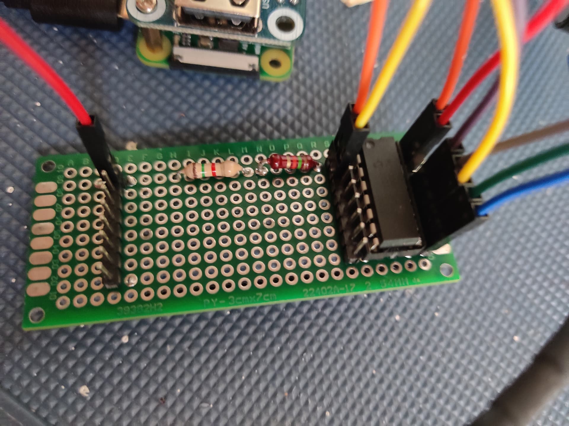
Can’t change anything with the cables sadly, they are laying inside concrete without a cable channel most of their way and I don’t really have space in the end for a sensor. I built a circuit to reduce the noise though and it works quite well with the analog input on the Arduino I don’t see it flipping to even 1. I can see a digital input work, it’s probably just the PI being way too sensitive and only reporting voltage rise and fall and not low and high.
The particular model you linked also takes min. 6V in, but the pi operates it’s serial at 3.3V. I’ll check though if there’s maybe something similar with 3.3V I ²C on AliExpress.
I’m a software engineer though and not an electrical engineer so I’m not 100% sure if that would be the correct components.
Could maybe also use the same processor as in my uno, but use it with a lower input voltage, so I can use the I²C capability instead of serial: www(dot)sparkfun(dot)com/products/8636
Also, it sounds like you’re maybe building something like this, but without the wifi or the giant framework.
The particular microcontroller+fingernail sized PCB with flash and pins is about 50 cents and has 3v3 serial and 2gpio that can be used for various things.
You can still run setup+loop code, or can do FreeRTOS tasklets straight in the SDK.
It seems to be more or less just the way the pi works that seems to be problematic. I’ve got it working with an analog input and it’s working fine, even with the unclean power input, so it think I’ll stick with analog.
Interesting project, but I think the chip they’re using isn’t really the right one for my use-case.
Did some more research and came up with the MCP3008-I/P, which seems to be ideal for my use with the PI (2.7-5V SPI) and which allows the use a different reference voltage, so I can use 5V as reference voltage. I’m not 100% sure it’ll work (fast enough) but it’s the best I came up with yet.
It’s a shame we can’t get a regular Raspberry Pi GPIO input to work. Have you tried using pullup resistors instead of pulldown? This tool is where I would start for prototyping and testing. If you get pigpio to work, you could run pigpiod on the pi and connect to it from your Rust program.
Yes I’m pretty sure I’ve tried pull-up resistors and yes I was using pigpiod, but as soon as a larger load hit the grid (e.g. starting a roller shutter motor or starting a vacuum) it would do a phantom trigger, probably because the reference voltage form the powersupply dipped and because the lines for the roller shutter run parallel to the trigger lines for a short run, so it might also be a bit of EMI, I think it’s pretty much just down to the more than less ideal conditions.
Also it’s a PI Zero, shouldn’t make a difference I think, but maybe worth noting.
Have you looked into debouncing techniques or other smoothing approaches? The idea is that you keep the last n readings and only signal a state change when the average passes a threshold.
Yes, I have, but it makes me loose short presses, which would be annoying and 100ms still wasn’t catching everything, it was catching a lot, but not everything.
SPI communication is working like a charm… Only thing a bit weird is that the reference voltage cannot be 5V because it increases the 3.3V lane (Vdd) to 3.9V either that’s nothing the IC was designed for or there’s a soldering error, but it’s still working fine at 3.3V.
Thank you for all your suggestions, that ultimately lead me to get this far.
Maybe one day I’ll do a write-up of this basically 100% opensource (secure) LED control (it might not be the best, but it’s software defined and modifiable all the way).