in my parents’ house there is an electric gate opener. In its control panel there are two power sources, one is the default local AC power from the grid, the other one is a 12 V backup battery pack.
That backup battery pack is small (similar to those in electric RC model cars), it doesn’t power any strong electric motors; its purpose is to provide power to the simple control electronics so you’re still able to buzz open a locked gate in case of a general power outage. The battery connection is just the two wires (red & black with red being positive, tested with a multimeter just to be sure).
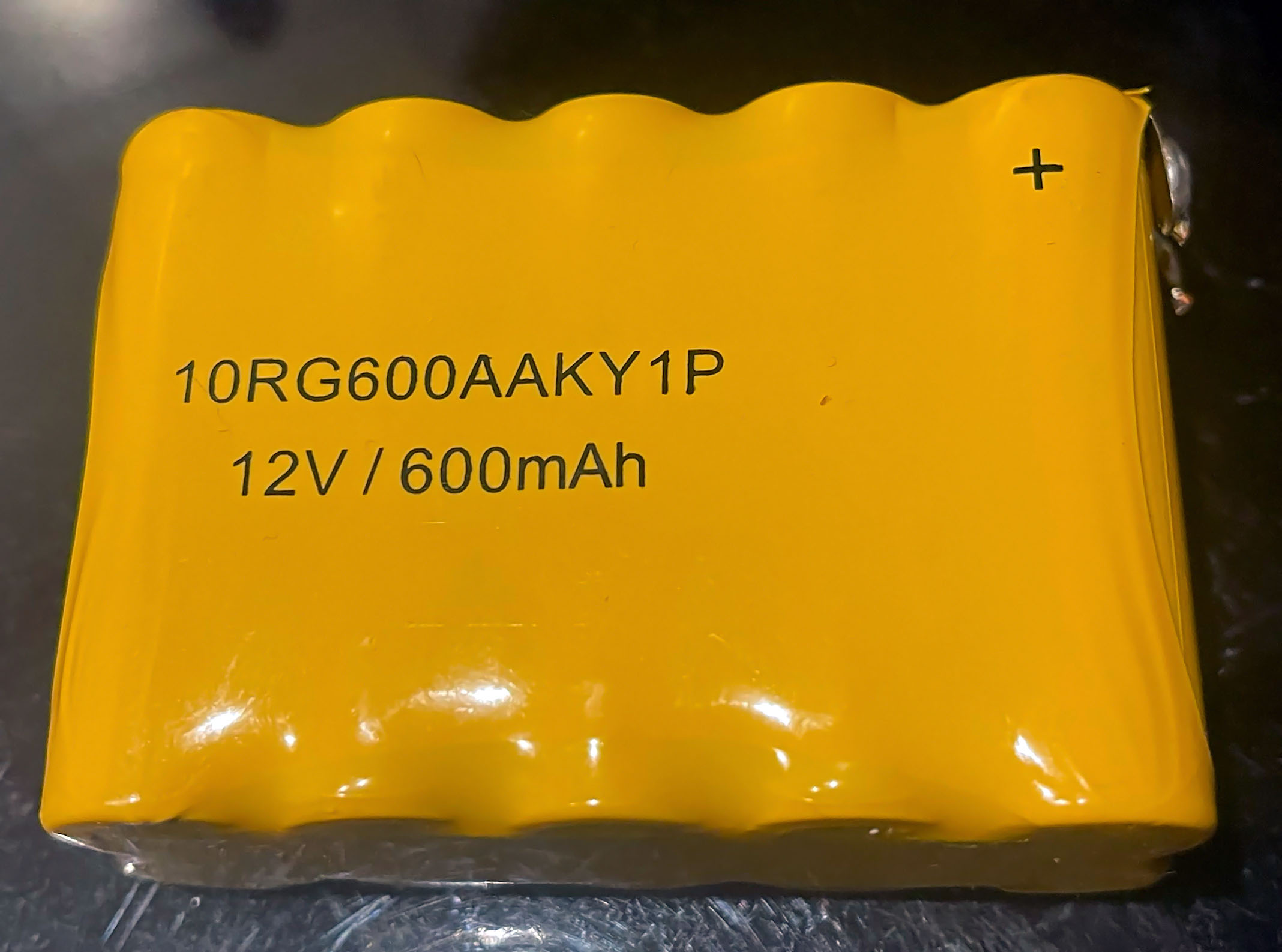
After 20 years that battery pack died (I think NiCd, looks like 10 AA batteries in a plastic wrapper, original pack rating 12 V/600 mAh). It had contineously been charged by the electronic control panel.
Annoying: Now that that backup battery is dead the complete operation is blocked.
The company that installed everything does no longer exist.
Is the following idea stupid?
These parts are already laying around, nothing would have to be bought:
An AC powerbank that supports “charge-through” (it itself gets charged and can supply an output like a proper UPS without any interruption in case of a grid outage) with 100 W max AC output
A 12 V/3 A AC-DC power brick
Is it safe to connect the 12 V DC power brick to the control electronics so that it itself thinks it always has a fully charged battery?
I’m not talking about it maybe not being able to deliver the required amps but the control electronics that expect a chargable battery to be there and not a DC power brick.
Thank you very much for the help!
(Unfortunately only had physics through middle school)
Use a diode to prevent the electronics back-feeding the PSU.
I once had to fool some device into thinking it had a battery by using a zener-diode and resistor so it could detect charge current into the fake-battery.
Should each wire get a dedicated diode (installed in opposite polarity)?
DC wires and clamps/connectors are not an issue from my little PC fan or periphals powering projects, but am unsure about any electronic stuff on that basic level.
If current can’t conduct through one diode, the circuit won’t complete and therefore no current will conduct through the other side of the PSU. Only 1 should be fine.
getting into the weeds a bit here, but if the electronics requires strictly 12V and the power brick provides a regulated 12V then there is going to be a 0.6V drop across the diode when you connect it to the DC wire, so the control elecronics will see 11.4V and not 12V
it should be okay since this thing is designed to be battery tolerant, but something to be aware of
I’d like to learn a bit, for example for battery-powered LED lights where the battery is dying and are to be supplied with DC power adapters with more exact target voltages:
Does this 0.6 V drop always have to happen? Or is it dependent on the diode model?
Why is this happening? Does a diode act like a resistor? If so, can you use multiple diodes in parallel to reduce the voltage drop?
If that’s not possible is then the proper way of planning to first boost the voltage to then result in the desired voltage after the drop?
If 3) is the way, what are the most efficient components for achieving this?
a diode is a semiconductor, and there is a voltage cost in operating it, called a “forward bias” because it takes some electrons to ‘dope’ the surface into being conductive, it is not a resistance in the sense that you are thinking because when it’s reverse biased, the resistance is essentially infinite and when it’s forward biased then it’s almost no resistance.
an LED needs a current-limiting resistor is because of this fact, you need to limit the current through them or else it will burn out
an LED is also a diode and has a drop across it, called a forward voltage
my first instinct is that it’s probably not necessary, if it is a battery circuit then the state of charge of the battery is directly correlated with voltage so it should operate fine on a reasonably wide range
i don’t think it is, but if you get an adjustable power adaptor you can adjust it to account for the drop across the diode if necessary
The control has a battery charge circuit, which could work by time , battery voltage, or both. 10 NiCad cells have about 12V when fully charged. The thing you want to avoid is putting a steady 12V at a certain current that won’t change. Battery chargers hate having voltage put into them. They avoid that by keeping the output higher than the battery voltage. Voltage goes from high to low.
There are also linear power supplies and switching power supplies. A linear wall wart is many times made to output a certain voltage at a certain current, because it was made as an AC adapter for a CERTAIN device.
If the current draw is too high, the voltage output drops. If it’s too low, voltage output goes up. So, if this system plugs in, or has some way to wire it with 120VAC, I would just get a UPS and plug it into that.
The the device will never know about power outages, charging batteries, and it should work.
AA rechargeable NiMH batteries are readily available. Why not just replace them?
Get 5 Pcs 2AA battery holders from Amazon. Use electrical tape to bundle them together.
If the original power supply (battery pack) provided a current of 3 Amps you will still need 3 Amps in order for it to work correctly. I get that you already know this. I’m stating it because there may also be the off chance that this device uses a logic circuit that reads the amperage. If not then I’m over complicating it and I’ll point you to MazeFrame’s advice regarding the use of a diode to prevent back-feeding to your power block. Let us know how it works out!
Thanks for all you guys’ feedback I get the diode basics now.
I visited today and did a little experiment:
Removed AC power from the control panel - everything dark
Removed the original backup battery pack
Since general AC power from the control electronics had been disconnected (so no chance of a charging circuit back-feeding) I then attached an old ISP router 12 V/3 A power adapter (wouldn’t matter if it died) to the now bare backup battery’s wires and “everything” in the control electronics panel lit up and some background light at the electric gate also turned on and the electric gate opening buzzer worked again.
Reminded me a bit of the original Jurassic Park movie
While this 12 V power adapter supplied the electronics I had it plugged into an AC power meter that showed a power draw of 8 W from the AC side which includes all the efficiency losses from the AC-DC power conversion.
Under load that AC-DC power adapter supplied 12.20 V according to a Fluke 117.
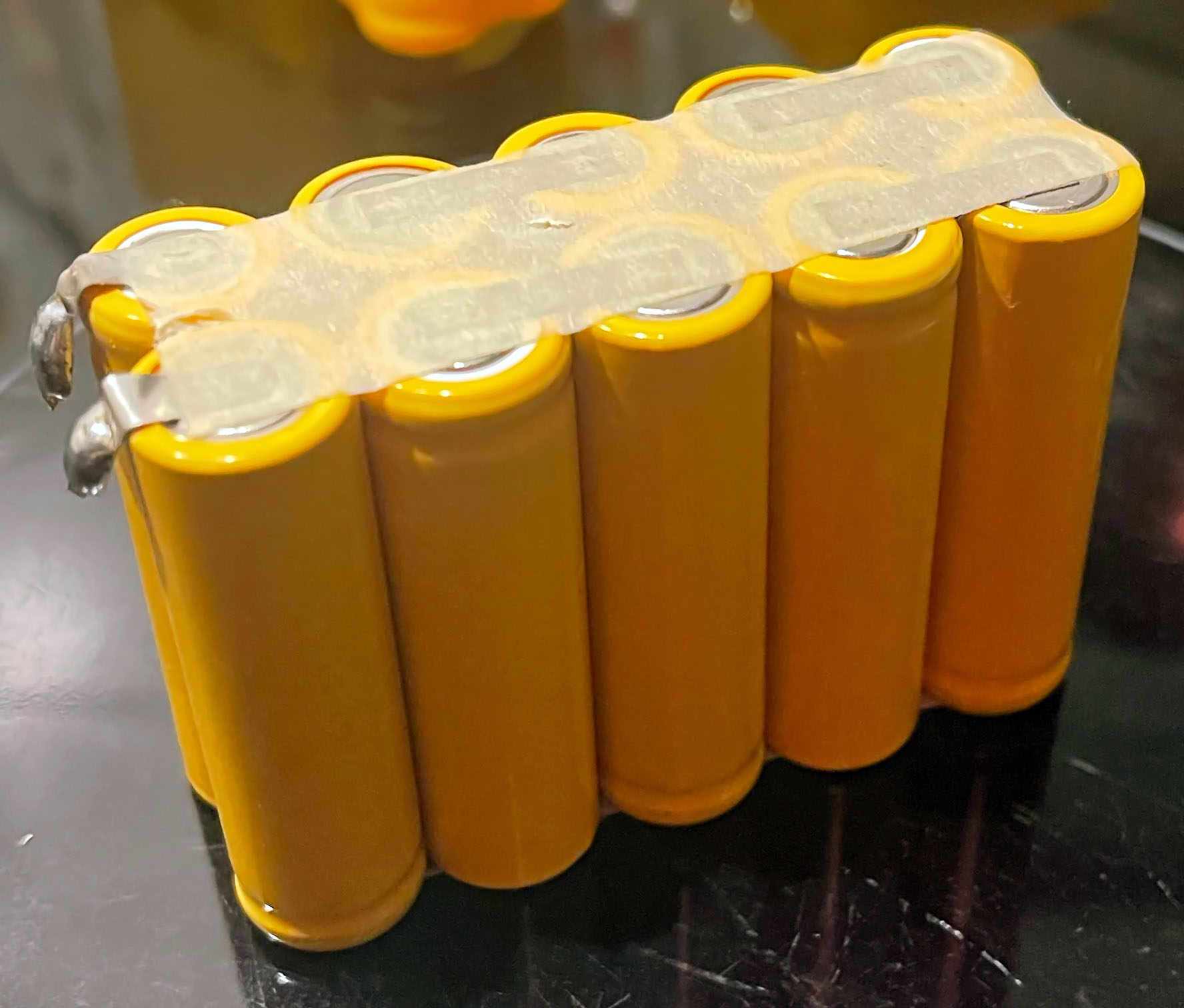
I made a photo of the original backup battery pack, the only writing and specs on it are:
There are absolutely no charging electronics in the original backup battery pack (the cells are just spot-welded with contact plates in series to get the 12 V)
My guess is then that they in fact just permanently got charged by the control panel electronics to a certain voltage
I’m not against that in general, I just have much negative experience with name brand NiCd (as a kid with RC toys) and NiMH 1.2 V batteries later in life regarding their reliability.
Thought that I would be doing something good for my parents making a contraption with a proper LiFePO4 powerbank supplying power to the control electronics instead of getting batteries again that seem to fail in the most unopportune times.
What would be the “best” 1.2 V cells for a DIY 12 V battery pack regarding the highest possible output current and that can handle permanently being connected to a “dumb” charger?
Note: The 3 A current rating was a suggestion from me after searching online with the result that most rechargeable AA NiCd cells don’t even handle that much current.
Also makes sense since then even with 100 % efficiency that would mean in case of a power outage the original backup battery pack would be empty after 12 min of operation which would be absurd.
you either have cells that are capable of huge current (which means low internal resistance in the cells) and you need external charge logic to keep yourself and the device protected from over charge/discharge
or you have cells with mediocre current, high internal resistance and be able to belt it all day every day with a dumb charger, set and forget
In your scenario I would buy a cheap AA battery holder for 12V worth of cells, piss off all the spot welding and shrink wrap and just have a plain battery holder
buy cheap NiMH AA cells and chuck them in and forget about it for a few years, when they die simply get new ones and replace them
I’ll get a 10 piece AA battery holder for 12 V when using rechargeable NiMH batteries.
Ikea Ladda AA 2450 mAh cells seem to be constantly good if they are made in Japan and are to have a low internal resistance.
I looked for ones with a high capacity since if I understand it correctly if you don’t have a choice and the NiMH cells are constantly charged with a dumb charger, they are the happiest with less than 0.1 C. Since I have no idea what that electronic control panel applies but the original battery pack had 600 mAh I think expecting a charging current of < 245 mA should be realistic.
Should I charge them fully individually before installing them in the battery holder that connects them in series?