Dishrec: an open source audio bodypack recorder with global timecode

Dishrec is an embedded audio recorder I’m developing, and I’ll be chronicling my journey, here (for now, at least). As some of you know, I’m an audio engineer (production), but I do know some programming, and ultimately aim to create tools that I and others like me can use.

The summary:

2 Likes

A couple things:

As I understand it, most audio programming (DAWs, vst plugins, etc) is done in C++, and PlatformIO allows me to write basically std C++ code and it will compile and upload it to the ESP32. So while I could use C and write bare-metal code for a cheaper MCU, one aim is to make the code more portable so that I can use it in other audio projects that aren’t embedded.

Beyond that, I quite like C++, compared to C. The logic is clear when interfacing objects at higher levels, so I find it pleasant and more manageable. It is merely a personal preference, but I prefer something like e.g.,
sdcard.write(buffer.get())
vs
sdcard_write_buffer_to_current_file(get_current_buffer_output())
or whatever that may look like.

On this device, the plan is to receive timecode through periodic re-jams from dish.tc, which uses dark magic to receive a timecode signal via satellite.

There is a market for low-cost embedded recorders like instamic, but they all suffer from the same problem- no timecode. I bought 5 of the instamic pro as a sort-of disposable lav, and after losing 3, I’m glad I didn’t spend more. The mics on them sound good enough, but syncing 8 of them + 3 actual audio units and 4-5 cameras is just cumbersome. We read the jammed timecode coming from our recorders into the mic at the head and tail of the file, then sync in post by manually modifying the metadata to reflect the timecode we read minus the elapsed duration from the start of the file. It’s a pain, and it’d be great if dishrec could just catch TC within a few seconds of booting and stamp the file right away.

Thanks; if you feel like contributing, you can do so at the dishrec github repo.

I haven’t chosen one, yet, but it’ll be some flavor of open source.

3 Likes

Today, I ordered another round of equipment to try out.

At first, I was looking at audio codec ICs, but the SNR on all the ones I could find is too poor* (this is where having production experience is handy); I knew I should be looking in the -120dB range, and everything I found was around -90 to -105. I figured I should try for just converters and wire to an ADC directly, then go from there. After all, the headphone out can be either hooked up to DACs, or I can use the internal converters on the ESP32, as long as I don’t run out of I2S I/O. So, after some reading and searching, I settled on:

(Both from TI)
PCM4222 ADC
OPA1611 op amp

These are high quality components, and will bring down the margin, for sure. Ultimately, however, this device needs to do one thing exceptionally: record clean audio with timecode.

*It turns out, codecs are mostly useful for things like mobile and IoT devices. Makes sense- hardware DSP, high channel count, and small footprint.

One note on the 4222 being multichannel: I’m going to attempt to lean in the direction of dual converters per channel for automatic splices above 0dBFS. We’ll see if that makes it in, but it’s nice to have the option of either stereo or extra dynamic range, when it comes to hardware.

While the parts are in the mail, I’ll attempt a schematic and PCB design, which will also be open source. I’m used to EasyEDA, but if anyone has a suggestion for something more conducive to a swifter workflow, I’m all ears.

Today, I mostly spent time with my family and only worked for a few hours, but I did feel as if I reached a small milestone in a confluence of my experience with production, prototyping, and software engineering (beyond the SNR thing). Trivial, but endearing.

5 Likes

Just after the last update, I realized a silly mistake I made- the opamps need to be fully differential for the actual audio input, so that’s now a TI OPA1632, while the 1611’s will serve as buffers in various places around the circuit.

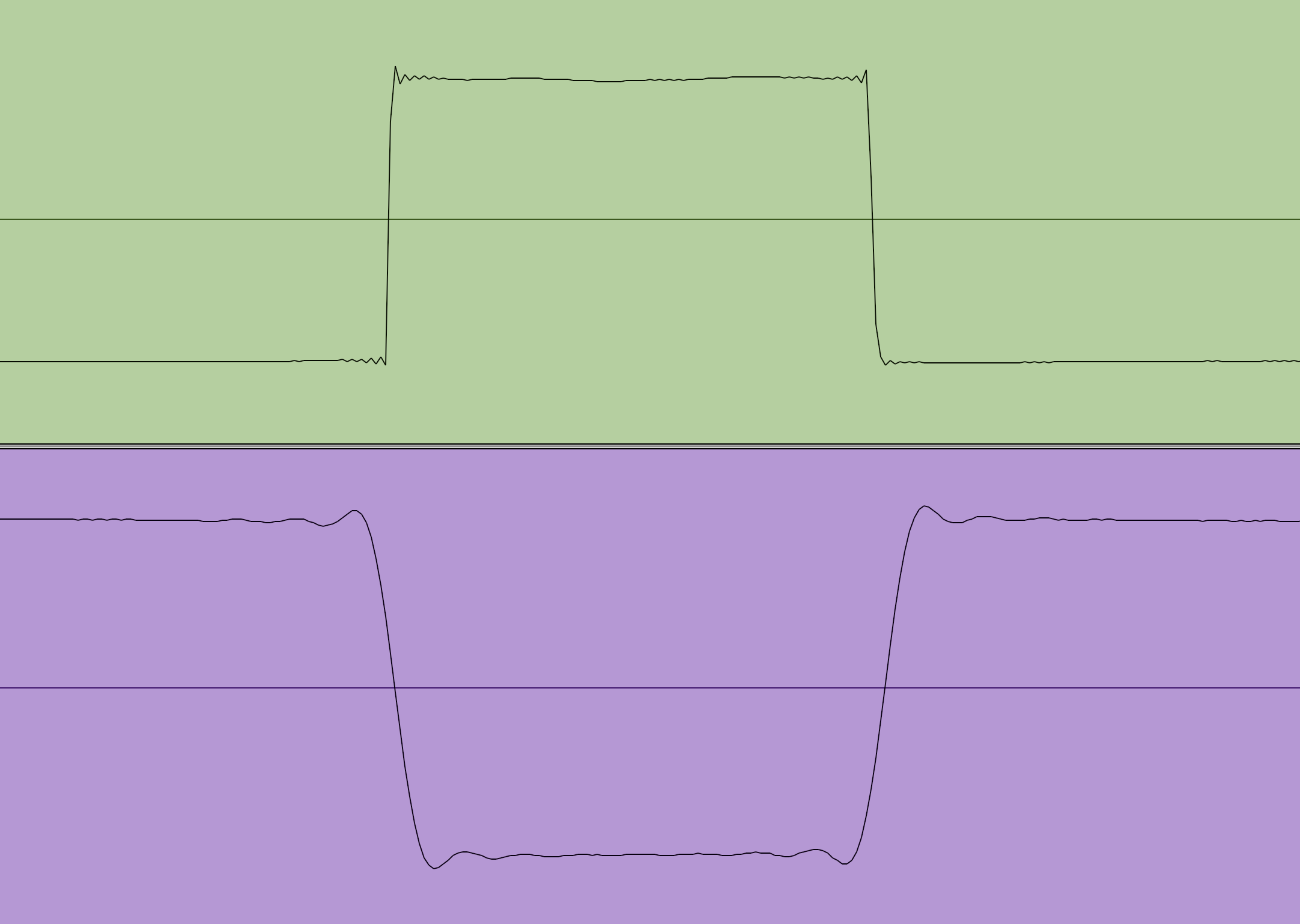
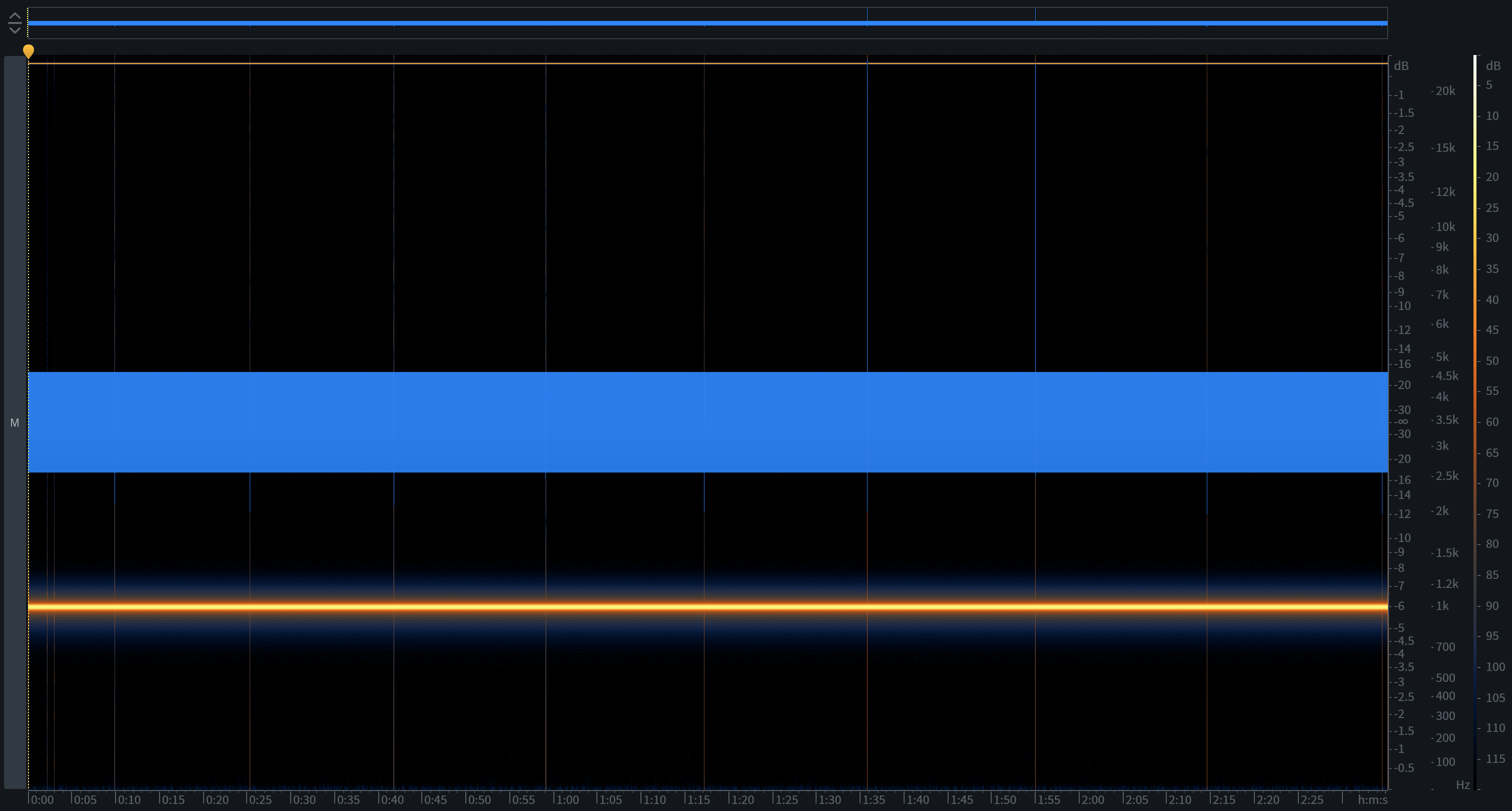
Yesterday I revisited an LTC library (also ESP32) I had worked on a while back. I’ve learned enough since then to realize it needs a brutal refactor, and I finally realized how to (hopefully) generate reliable LTC output.

Previously, I was using the onboard DAC with interrupts to output each bit. The clock would stay synced over long periods of time, but would jitter forward and back every one or two seconds.

What I didn’t realize is writing to the I2S DMA buffer on the espressif chips is a blocking operation, and doesn’t need to be called with interrupts or delays. I was stuck in profiling hell before- measuring the duration of each function so that the edges would rise and fall at the exact right moment, then writing directly to the DAC output, only buffering the next bit to be written.

Now, I have a ring buffer that I can write to, which dumps it’s available data into the DMA in another task. This is the same method that writes data to the SD card from the DMA as it comes in for dishrec.

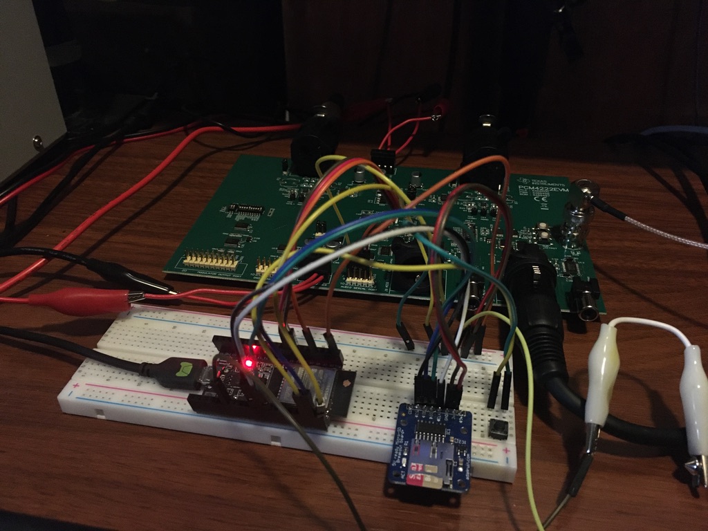
And speaking of dishrec- I have the EVM board in and powered for the PCM4222 ADC, with a barebones class written to interface with it. I’m also switching the production chips to the PCM4220, since it is pin-compatible with the 4222. The only reason I chose the 4222 prior is because it’s the one on the EVM.

Ok- back to timecode:
While writing the BWF iXML portion of the wav header code, I had more realizations. CD audio is 44.1kHz, broadcast is 48k. The difference is historical, but why 48k? I suspect it’s because It’s evenly divisible by 24, 25, and 30. The timecode we are familiar with reading in any editing suite is such:

hours:minutes:seconds:frames

The metadata that an NLE or DAW should read is the more ambiguously named samples since midnight. Though we use framerates that are 0.1% slowdowns like 23.98 and 29.97, the TC value still runs from 0-23 and 0-29 frames in each “timecode second.” So, because samples since midnight must be a whole number, the sample rate must be divisible by the rounded framerate. 44100sps / 24fps = 1837.5 samples per frame. That won’t work.
48000 / 24 = 2000, which means that at TC 00:00:04:11, SSM will read 214000 ((4 x 24) + 11 = 107 total frames * 2000 samples per frame = 214000).

After finally getting all that through my skull, it became clear that to correctly time LTC output at 23.98 and 29.97, I should probably just insert a 1 sample delay every 1000 samples to account for the 0.1% slowdown, as LTC output is real-time.

While I’m rambling, here’s another tidbit if anyone is interested: while we often abbreviate 23.976 as 23.98, the actual metadata representation of frame rate is a string expressed as a fraction; i.e., “24000/1001“, “24/1”, “25/1”, “30000/1001“, and “30/1”. :man_shrugging: This is stuff I’ve used for forever but didn’t know. Plus, I always wondered what samples since midnight meant.

2 Likes

A little more on LTC…

In last year’s iteration of LTC, I also played around with sum-of-sines square wave lookup tables (which I may go back to at some point).

In testing, I recorded my device as well as a zaxcom ERX into pro tools and analyzed the waveforms. Mine were sharp waves with rapid transitions, as expected. The zaxcom, interestingly, looked like a low-passed square wave, as if it were synthesized from an additive sin oscillator. This can be preferable to avoid unwanted harmonics created by the sharper wave edges. Of course, I didn’t realize I’d be using trigonometry past college algebra, but here we are.

Edit: Here’s a screenshot. Reflecting further, it could just be that a low pass filter on the zaxcom unit is smoothing out the waveform… not sure. Top track is mine, bottom is zaxcom. Either way… will update with new approach once I’ve tested.

Test recording with the hacked together prototype

I had some issues getting the bare ADC chip to work on a breakout board. Turns out the issue was once again what I like to call an “air gap between the ears.” I had the chip oriented incorrectly. Yikes (should’ve paid closer attention to the dot, rather than the direction the text is printed on the chip). A few more chips should come in this week, and I’ll resume development on that when they arrive.

Though few, there are occasional pops in the recording, but it’s unclear if it’s a shoddy connection or a software design flaw. The master clock out from the ESP32 is just alligator clipped from a jumper to a 1/4" to BNC adapter and then attached to the EVM. It’d have been nice if it was just another pin header, as that signal is upwards of 12MHz, but it works well enough to test with.

Note the low energy at the bottom of the spectrogram doesn’t appear to be DC offset (the ADC filters it out), it’s just noise. Another minor thing is that this signal is neither purely analog, nor directly from a microphone. It’s in through an interface, into PT, and back out. It was routed this way for testing both the input and output of the ADC EVM board, so I haven’t had to hook up any of the op-amps, yet, though I do have them soldered onto little break out boards for when the time comes.

I think the next milestone should be adding a BEXT chunk and combining all the wav header classes to correctly save a BWF (broadcast wav file), as this example is a vanilla wav with no timecode saved. I do, however, have some of that code written to create an iXML to save it into, as well as a basic timecode clock + tc arithmetic.

2 Likes

Dude, nice.

I suspect that when you build a more finalized version of that, some of the noise will be cut out.

One of the things I ran into when messing around with logic gates and clocks is that breadboards and wires like that provide significantly more capacitance than is ideal and can introduce noise and variability.

At least, I’m pretty sure it’s capacitance. I’m not an EE, so go ahead and take me to school.

1 Like


1k sin wave with intermittent errors. Turned out the problem with this was just interference.

I scratched my head for a while on this one trying to figure if it was a logical error or interference. The way I ended up discovering the problem was taking a phone call while recording test data through the ADC EVM and back to pro tools (to test the adc itself rather than the mcu logic, as the errors were a similar but not exact period between). When I left the room on the phone, pro tools was recording. While on the call, my phone hit 1% battery, and the call started to break up. I walked back into the office to plug it in, and I saw that the track was suddenly full of erratic peaks- the phone’s RF death rattle was flipping bits. That’s when I realized that while I’ve been testing, I’ve left my phone sitting on the desk only 12 inches or so away. :crazy_face:

I’m still having trouble getting anything from the ADC on a breakout board, so I shipped in some PCM4220s (less options to screw up) and a more specific breakout board. The other ones were variable size and have looong pads to solder to, so maybe I shorted something, despite looking clean beneath a microscope.

2 Likes

Been working on this a lot more lately and now have a custom data type for audio data. Reasons this is handy include:

  • packing and unpacking 24 bit audio (since 24 is not a power of 2)
  • not having to re-create buffers when changing bit depth
  • easier DSP

I also ended up adding almost full broadcast wav metadata support, so that’s basically a library of its own, at this point.

Next up is rewriting some of the I/O to use the new datatype and test some 24 bit input.

3 Likes

A bug, a bug, my kingdom for a bug!

Turns out my SD card died. But hey the device supports exFAT now so that’s cool

@khaudio Firstly, I am curious if you are still working on this, it has been quite a while since the last update.

Secondly, if you could humour me, what is the advantage of a timecode, presumably being stored as a second/third audio track since you mention LTC. I finally sat down and reread the thread and I cannot quite see what the disadvantage would be to simply store the current date/time of the start and end of the recording, rather than embedding it in a SMPTE timecode-in-audio-track.

Thirdly, it looks to me like dish.tc failed its kickstarter; where did you get it ah, I think I may have been looking at the dish pro kickstarter, you are probably using the first sold version which was funded.

Effectively, the dish.tc device is just a GPS, Galileo, or GLONASS receiver with an adapter to LTC audio, right?
The 3D rendering of the “Dish Module” on dish.tc has a module that looks pretty similar to the GPS antenna used on the FBI tracking device that iFixit disassembled in 2011. It seems weird how much dish.tc desperately tries to avoid saying “GPS” anywhere.