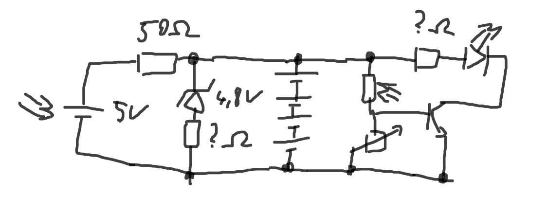
And while that would maybe work, unless I build my own solar module from individual cells, I am not getting 5V. For all those who never worked with raw cells: Solder them on a glass plate, NO pressure permitted, else PLINK and it is $ down the drain…
However: 6V cells (at 70mA) in the right size exist! Ready made and potted!
70mA can go directly to battery, no resistor needed (yeah… sure…)
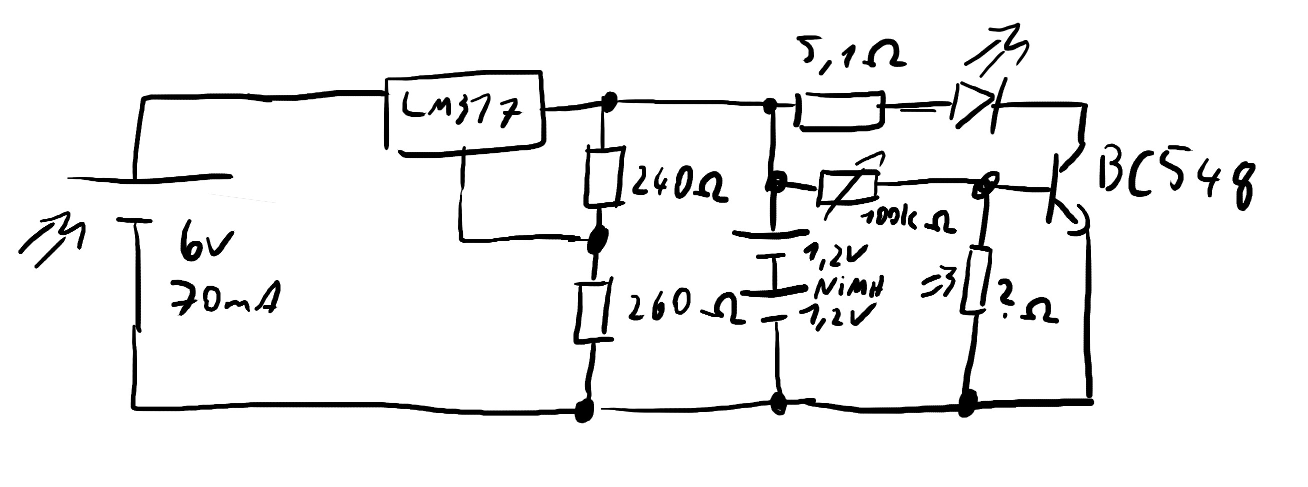
So, Napkin circuit but with slightly more thought:
Just from watching the voltage go up and down, there are some tests to be done with fan speed on the hot side. Blowing in the general direction of the cold side heat sink also creates huge jumps (as in: ±40mV creep).
In case anyone needs a super sensitive movement sensor on the cheap, this could be it
I planned on building a solar powered dehumidifier before. And seeing the drops build up and drip down at just 10W, that idea may soon turn into more than that.
Why solar? Why not just buy...
Solar in this case has a few advantages:
The heat in the form of sun makes it into my apartment anyway. Turning some of it into electricity for a short moment does not heat the room more than it just hitting the curtains or floor directly.
Automatically shuts down at night. No timers to set, no clocks to go wonky, nothing to forget.
No running cost. 10W for 8 hours per day at 28ct/kWh… yeah, the walladapter would be cheaper for the foreseeable future…
No idea about any of the characteristics on the photo-resistor. Is just w/e and compensate by using an adjustable resistor. Squarely in the “good enough” territory for this here.
Charge current is limited by what the Solar module can provide. When you got more current on your hands, put a 20Ω resistor (1/2W) after the LM317.
Does not seem too bad, does it? Well, “integration” is the next hill…
Notes:
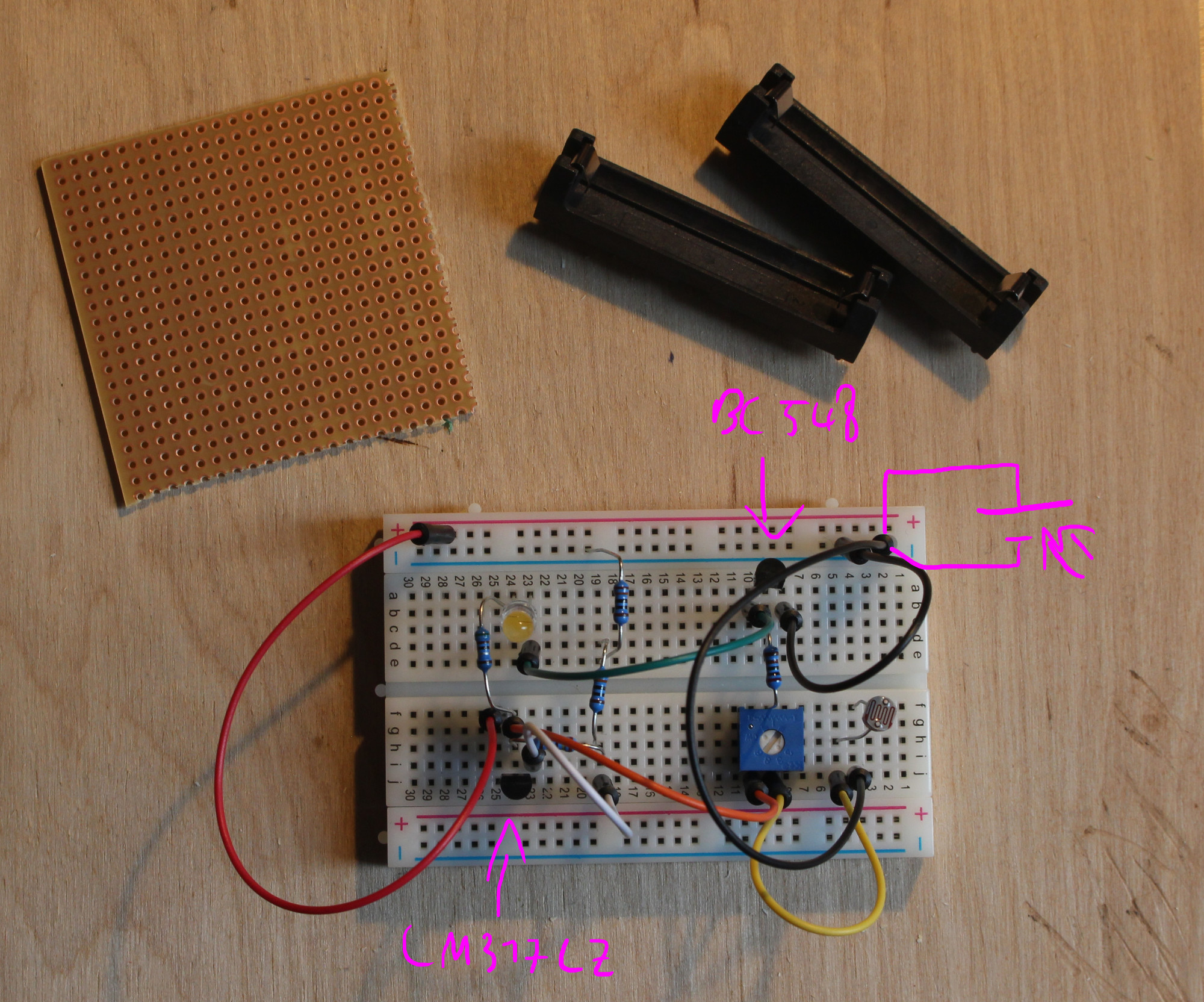
2x 130Ω = 260Ω, to explain why there is one more resistor on the breadboard than in the schematic
most of my jumpers are tied up in a different project, so excuse the color-
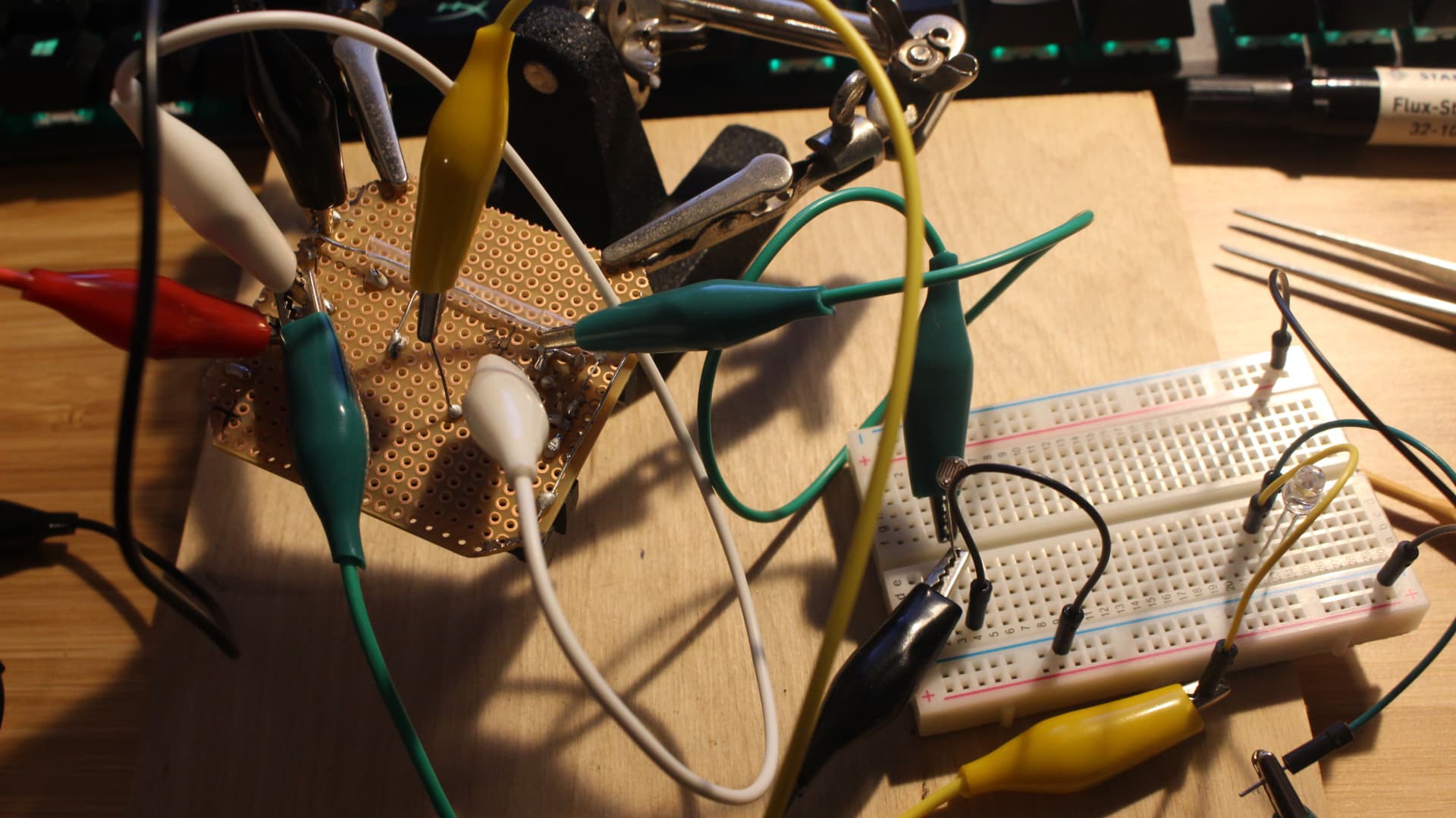
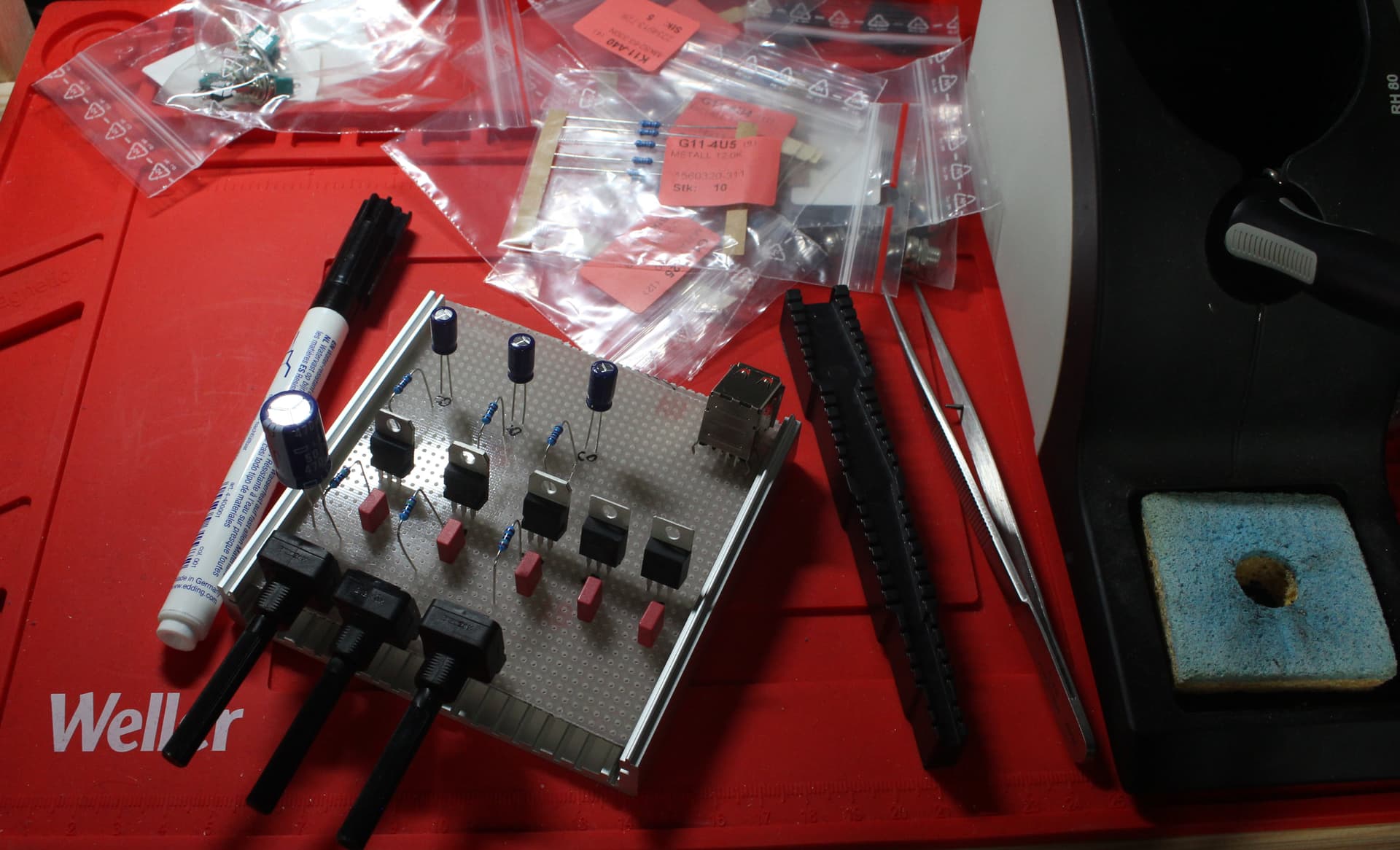
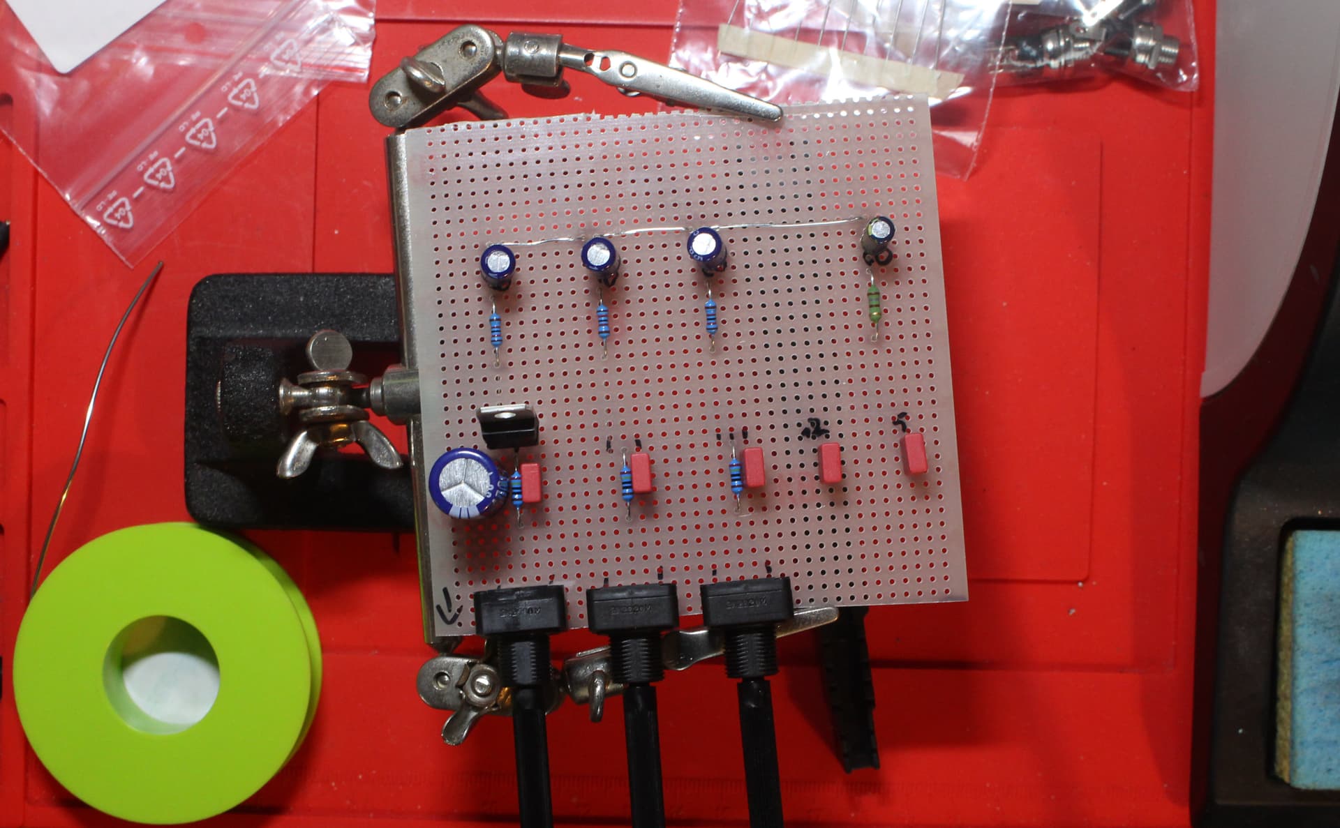
Protoboard
Is limited to 55x55mm with the corners chopped off. Since the old battery holders are also toast, I loose some space to the batteries.
Will have that sorted by Sunday (I think).
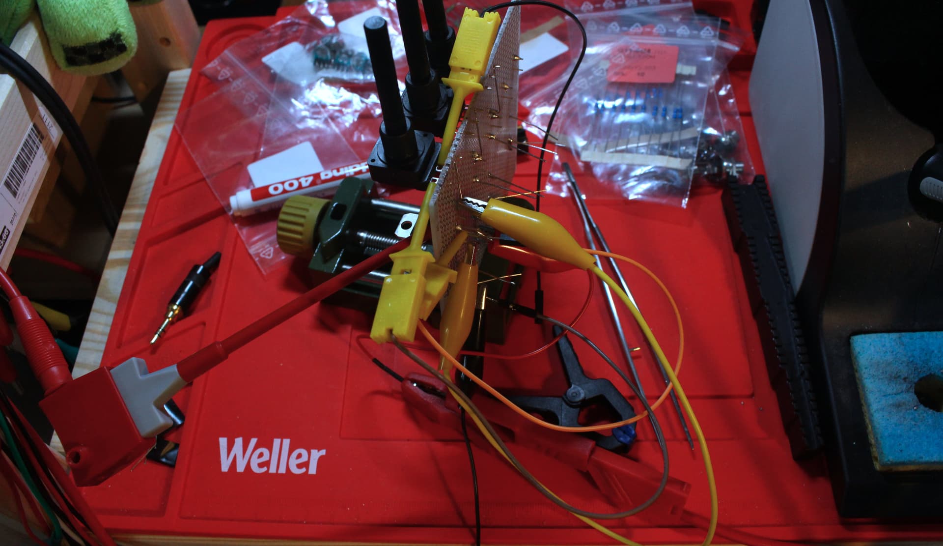
While transplanting the parts from the breadboard to the protoboard, I did a bit of an oopsi, or at least I thought I did.
Probing about, I could not find the blown part or open connection.
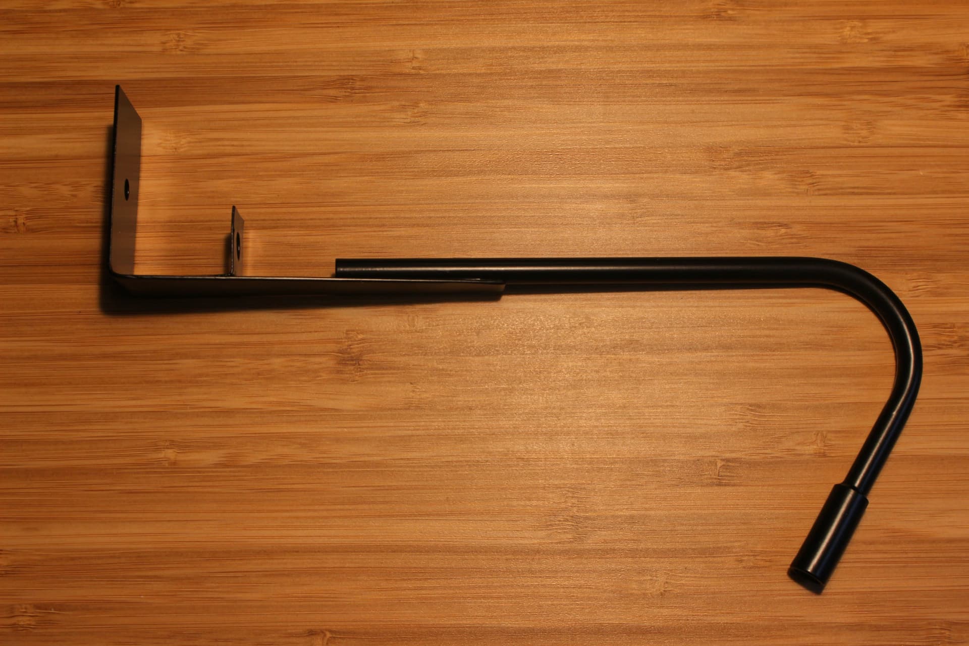
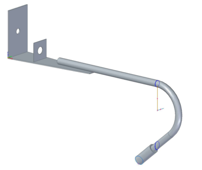
Them having a local current limiting resistor means any 12V DC system can power these. I may make some sort of cover for the back of the barrel jack and wires going into the tube.
I have 9.5mm black heatshrink, which obviously is the size below the one that would fit… Well F***
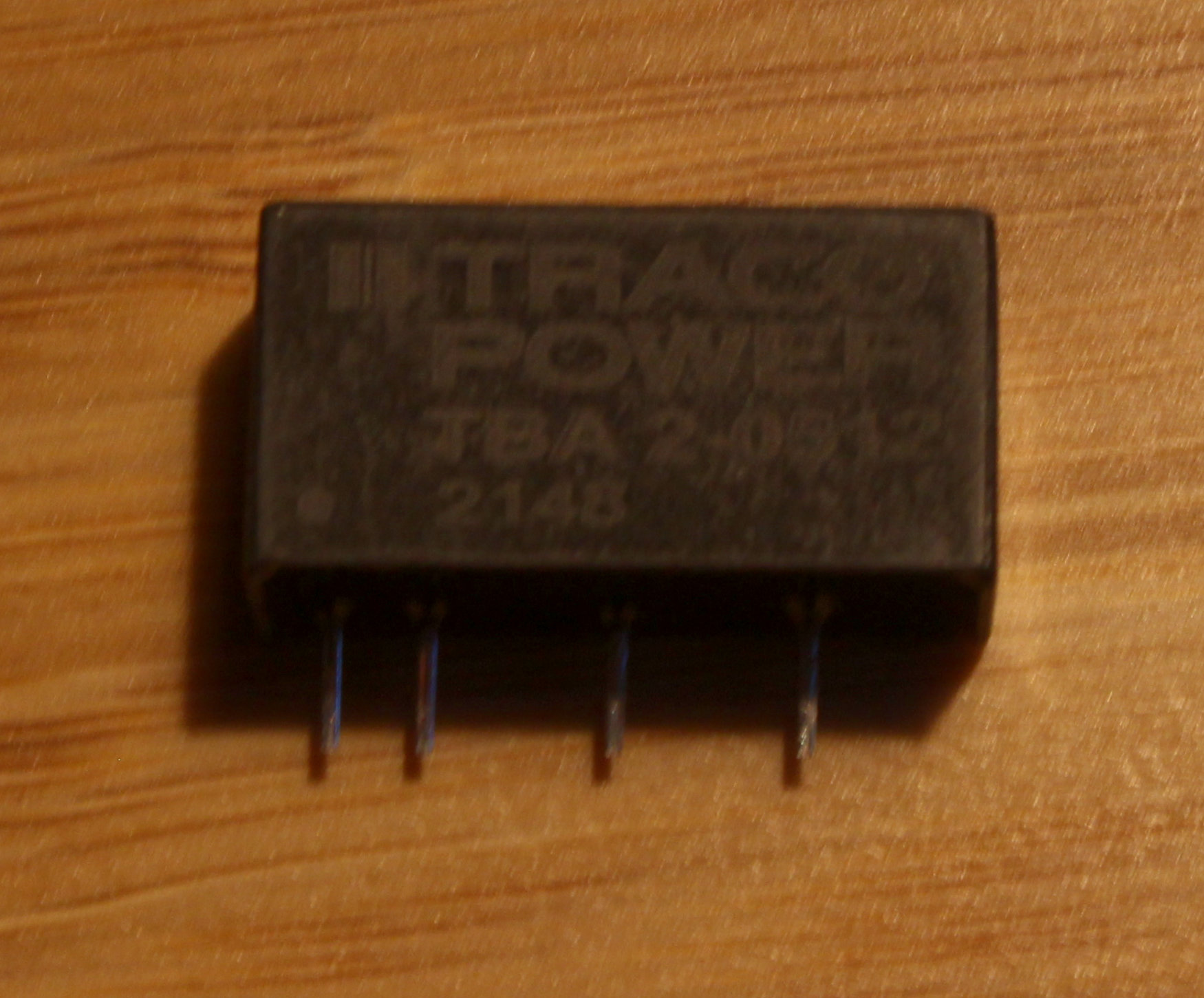
Was planning on using Traco TBA2-series DC-DC converters for some Op-Amp involving application. They are neat little bricks that need basically no supporting components, and provide electrical isolation while doing it!
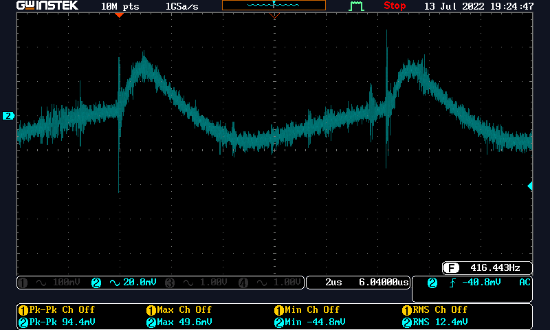
[Edited: Fixed Axis Colors]
At no load, you get >20V out of this thing. Which may or may not kill whatever downstream component you have there. I would suggest putting a Zener and resistor to put it into the 10% load range when “idle”.
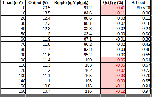
Output voltage deviation and Load (both in %) below. Spec sheet claims ±3% at 80% load. I am not seeing how to achieve that number, but half the time, it is in spec.
My data taken from a sample size of 2:
Conclusion
In practical terms, for more complex tasks than powering a motor or some lights, you need a Linear Regulator to clean up that dogs breakfast of ripple and voltage droop.
Trouble with the trusty LM317 behind this is the need for ≥3V voltage drop over the linear regulator, so in my case, I need a 15V output model instead.
Overall and for the price (4.40€), I rate these Meh out of 10.
Potential use case
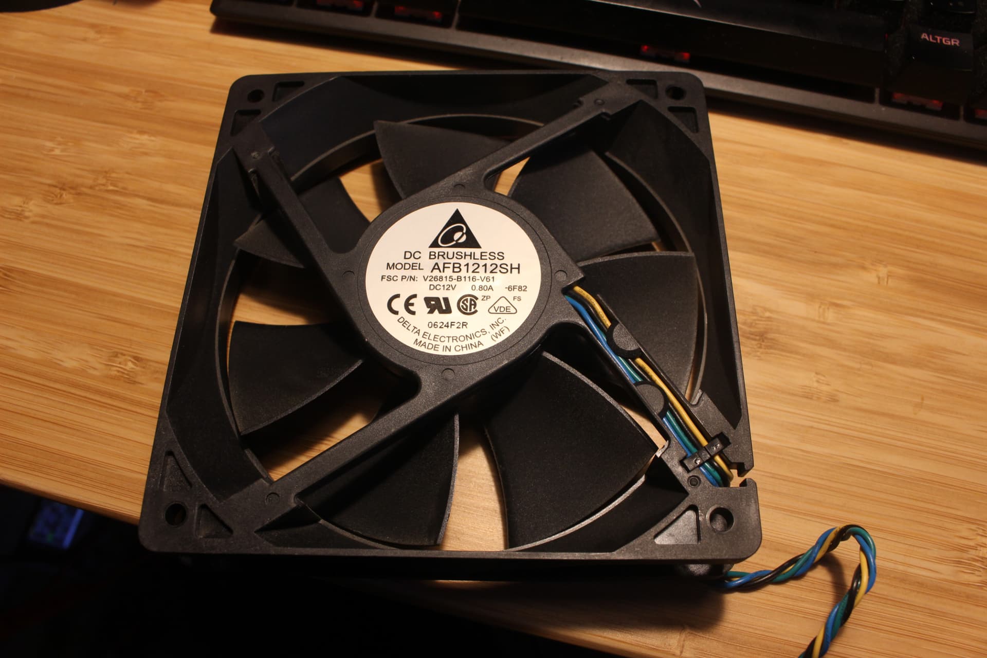
USB to PC-Fan adapter. Looks janky, works well though.
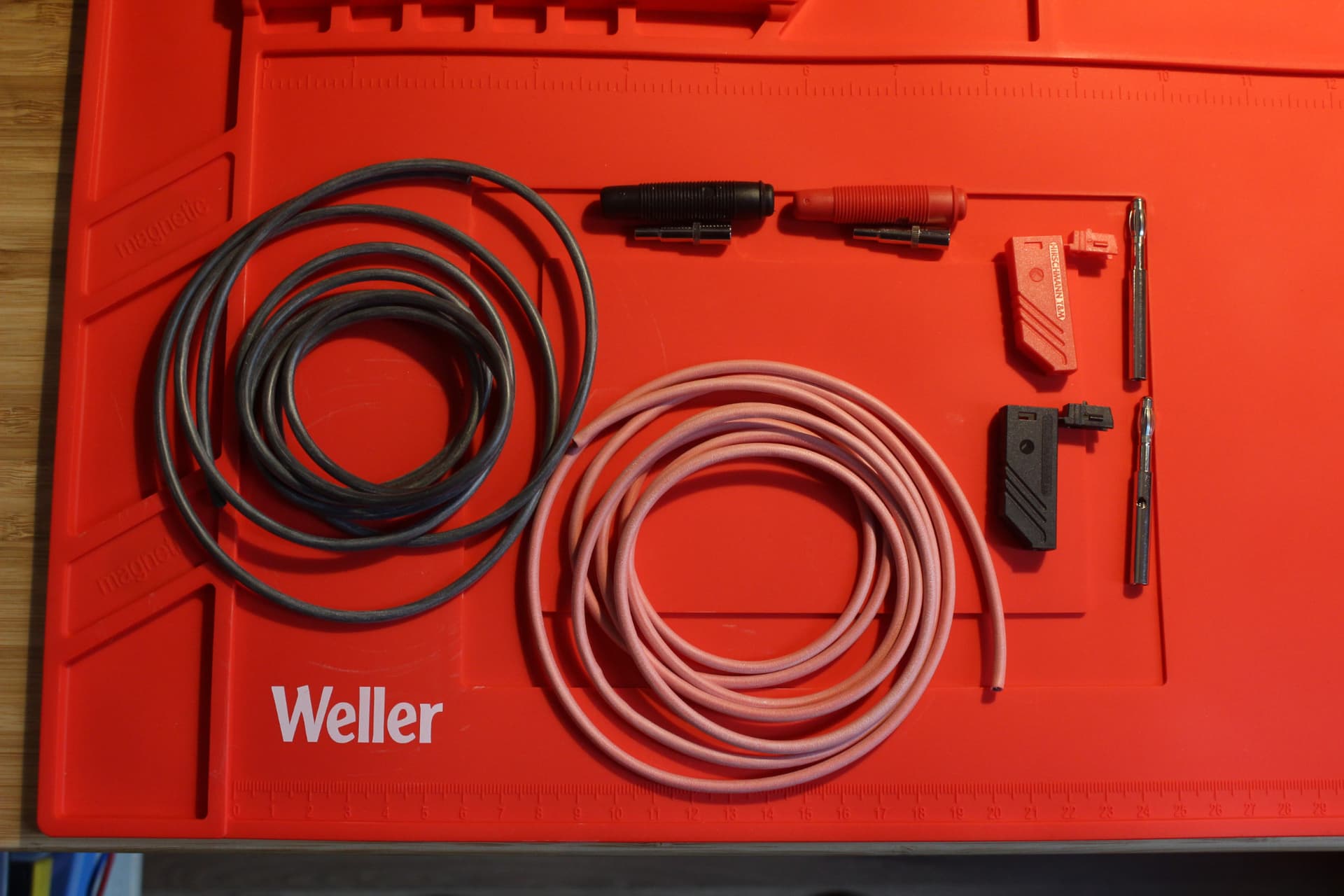
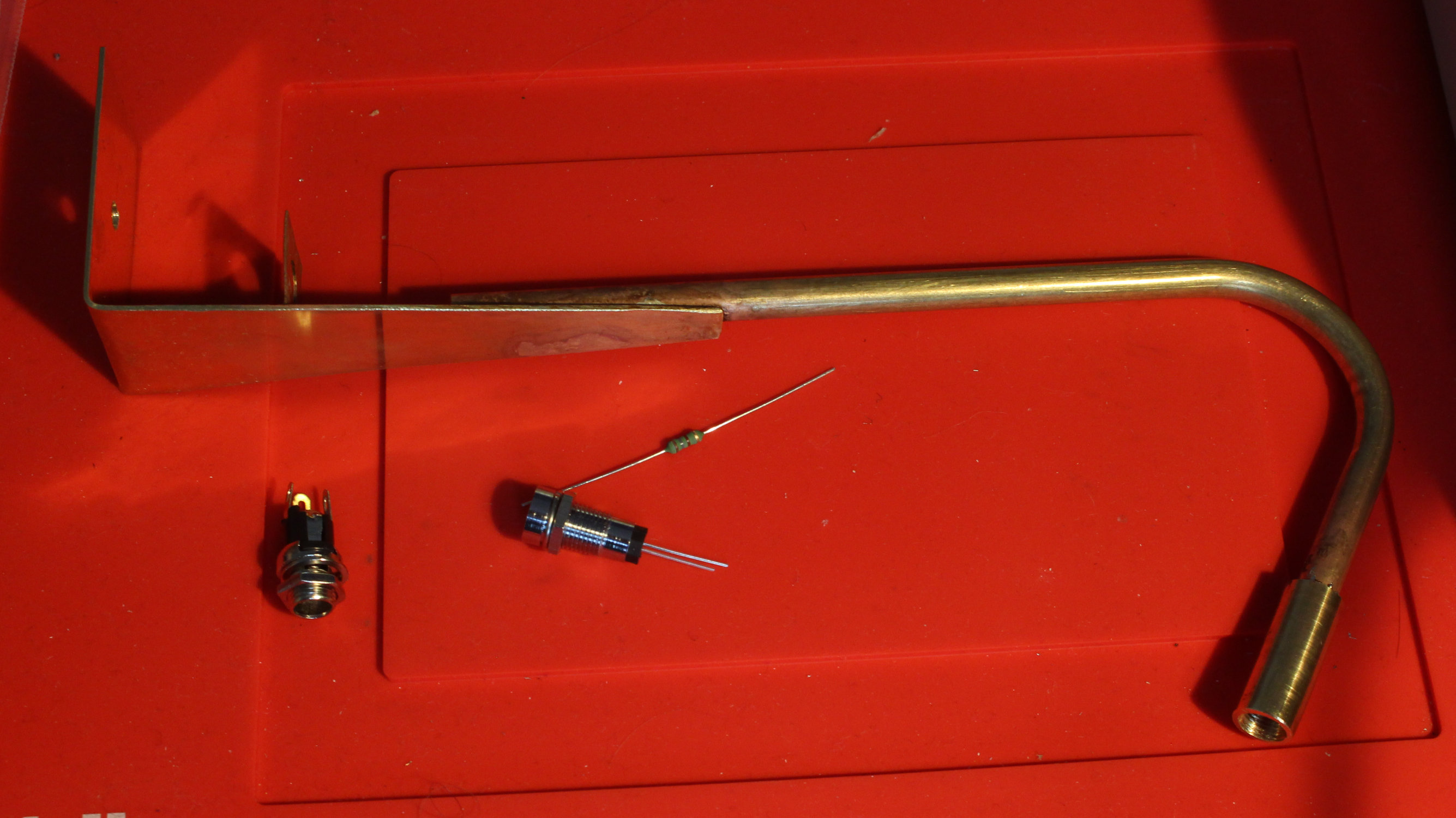
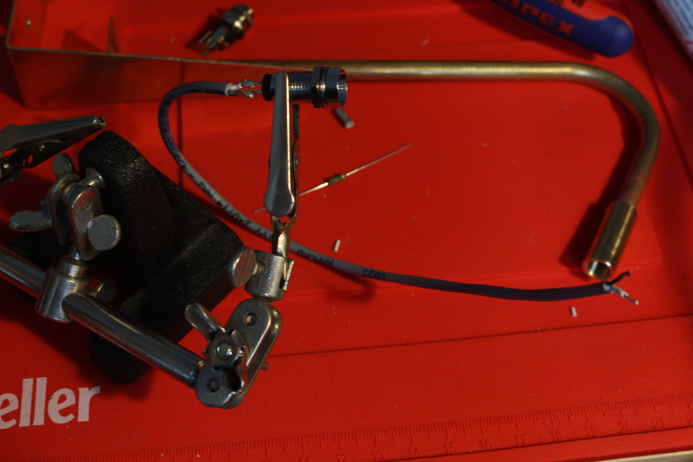
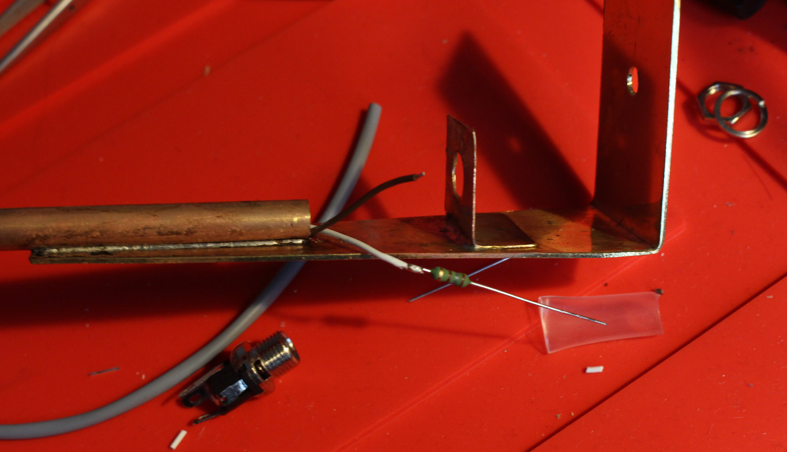
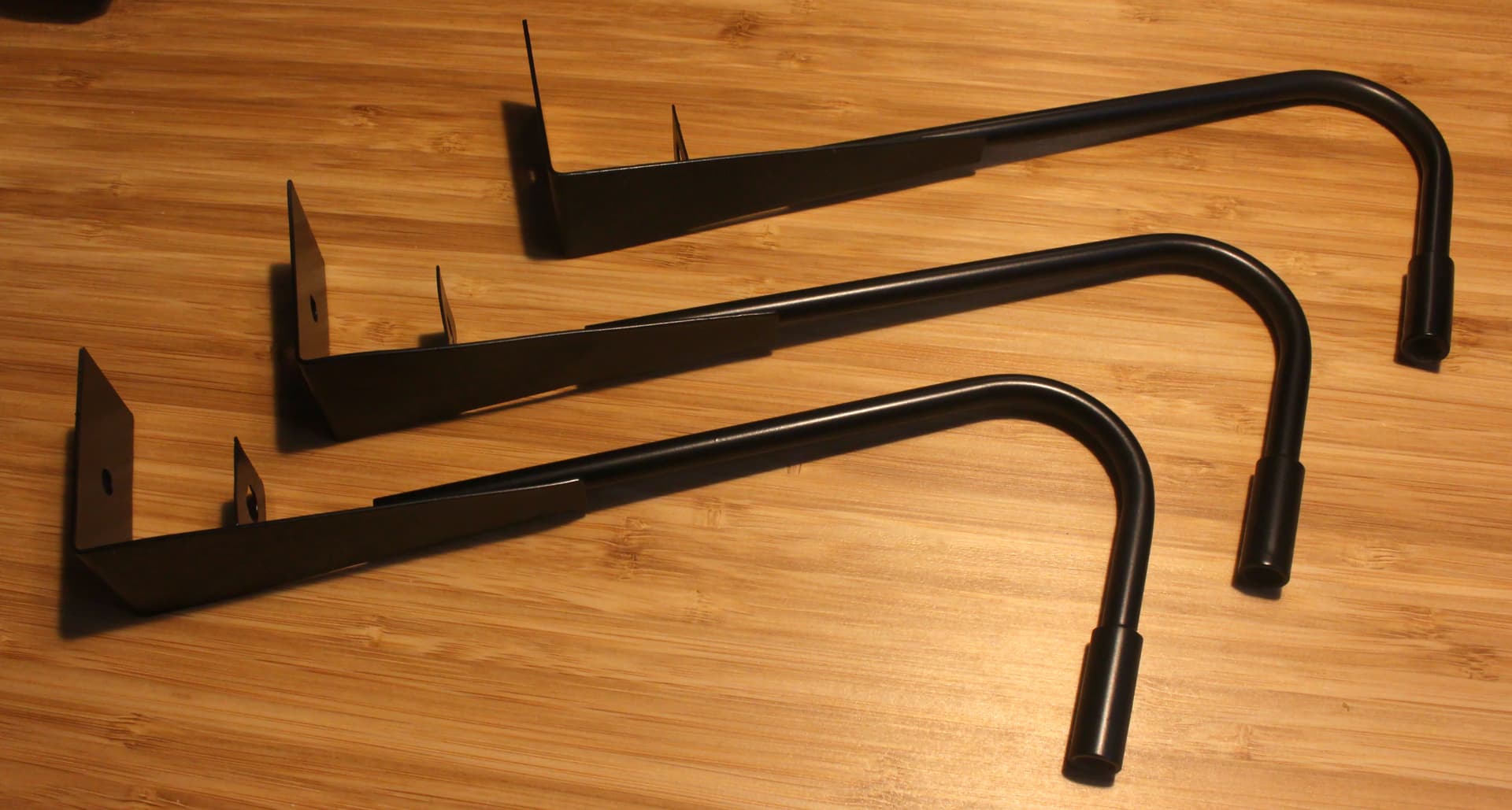
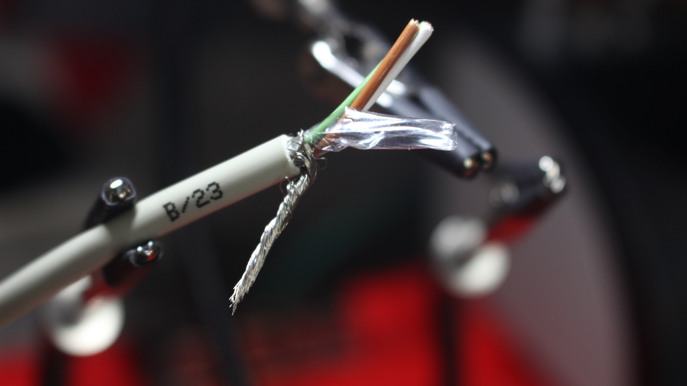
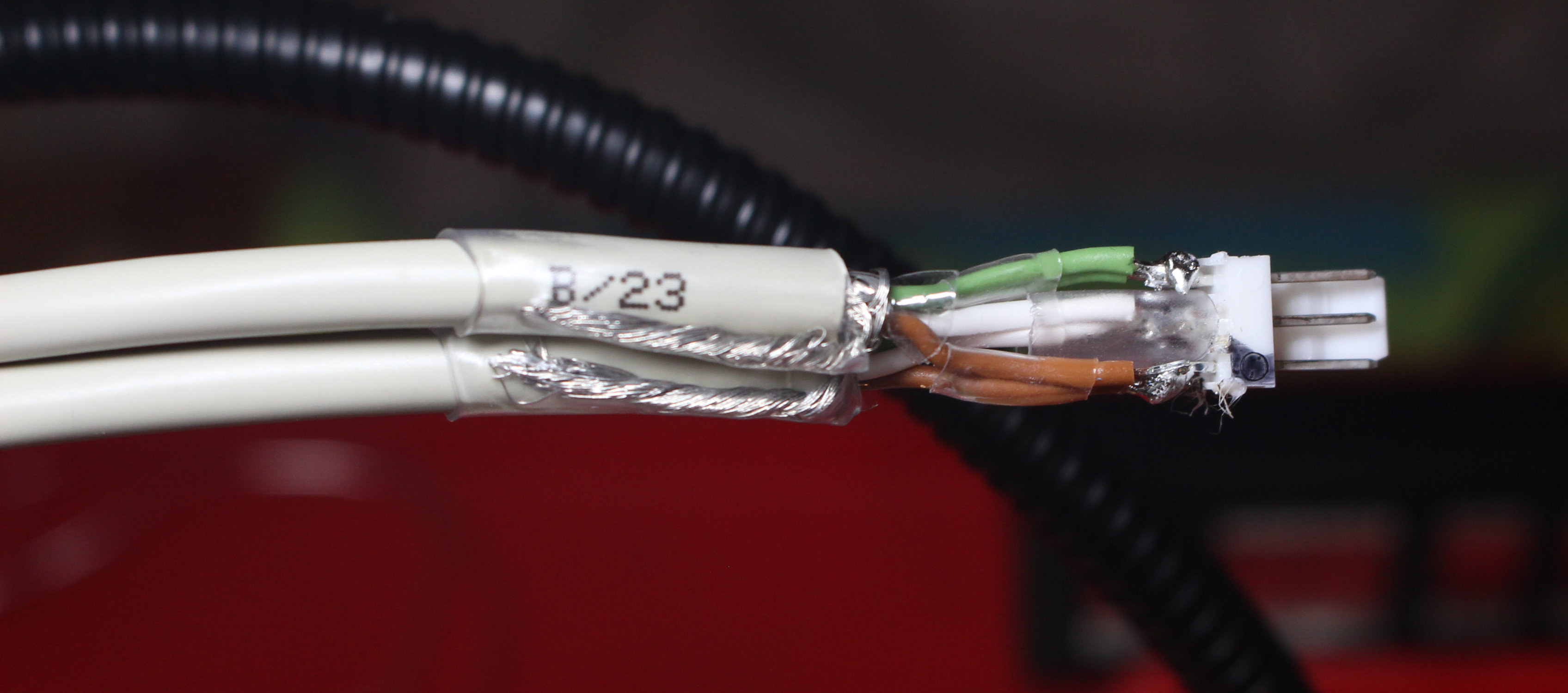
3 Drop-Cables made, these run from the lamps down to the “power cord”. 5.5x2.1mm barrel jack to Molex Micro Fit aka Fan connector. And yes, they are pin compatible
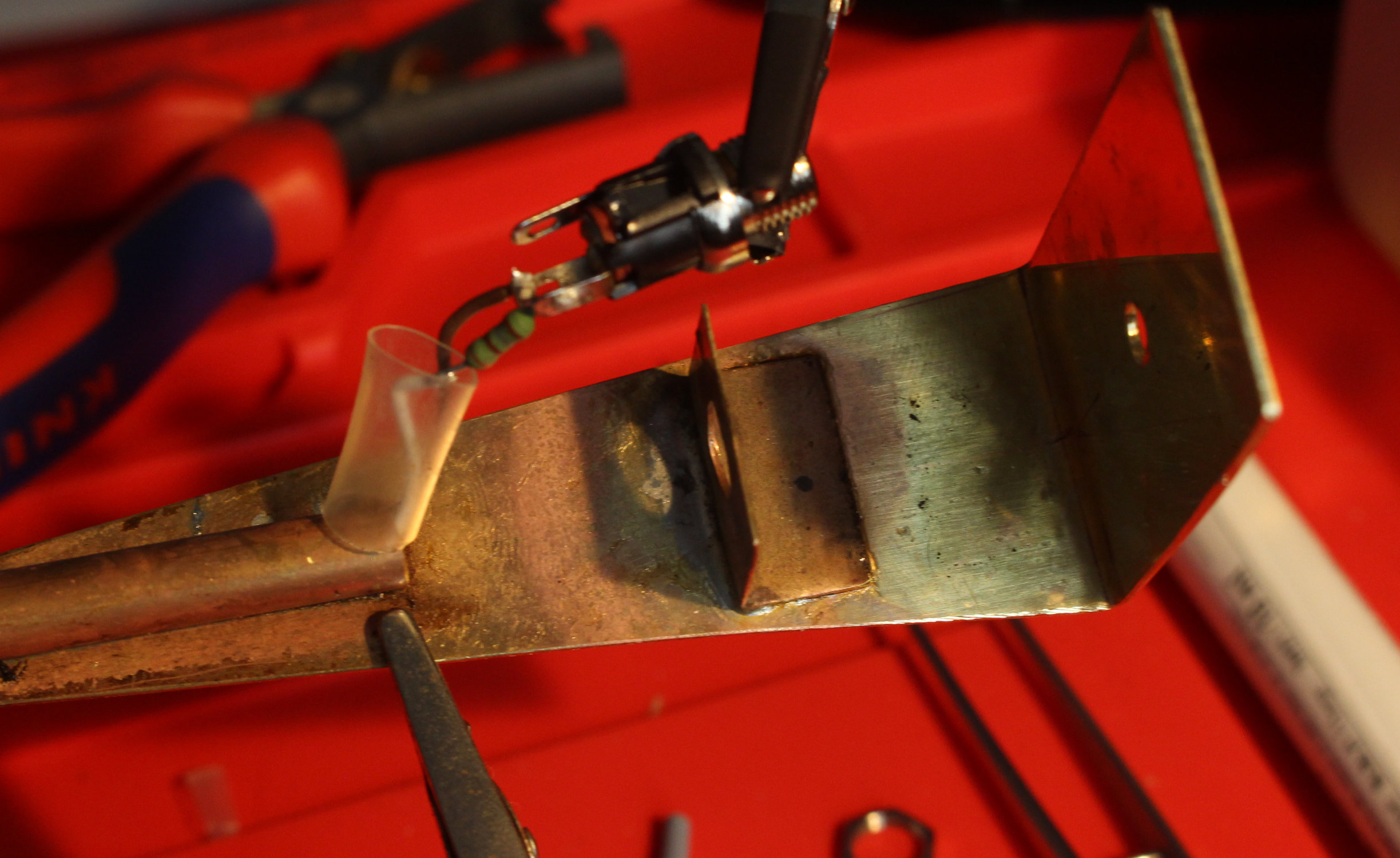
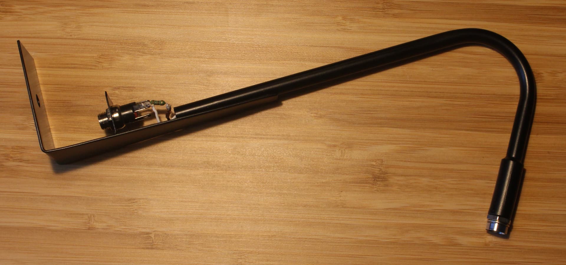
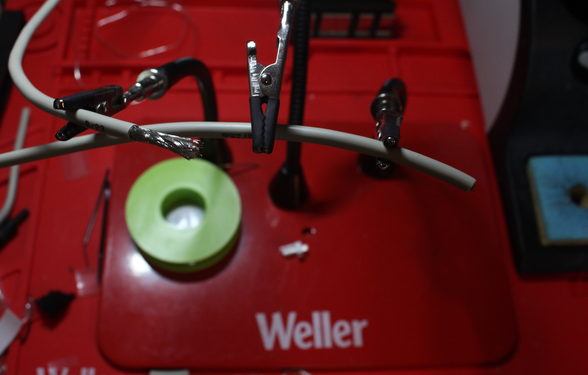
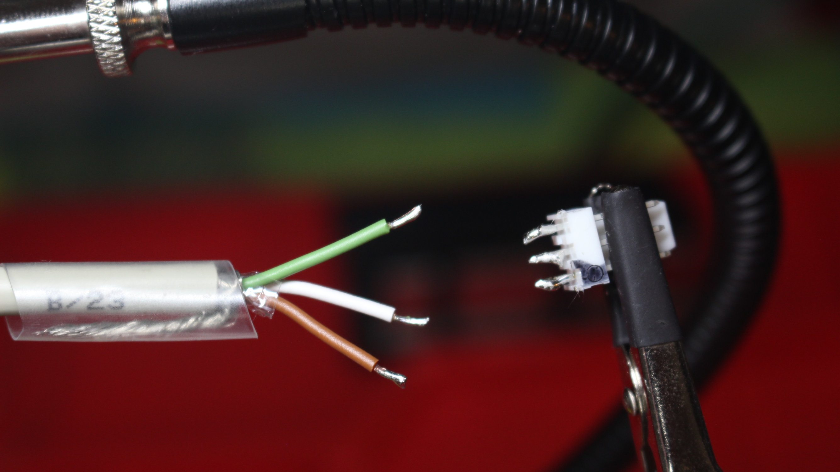
Piece of heatshrink to hold the shield out of the way. Else you will stick fine wire into your finger tips. Ask me how I know!
Tinned and ready for soldering:
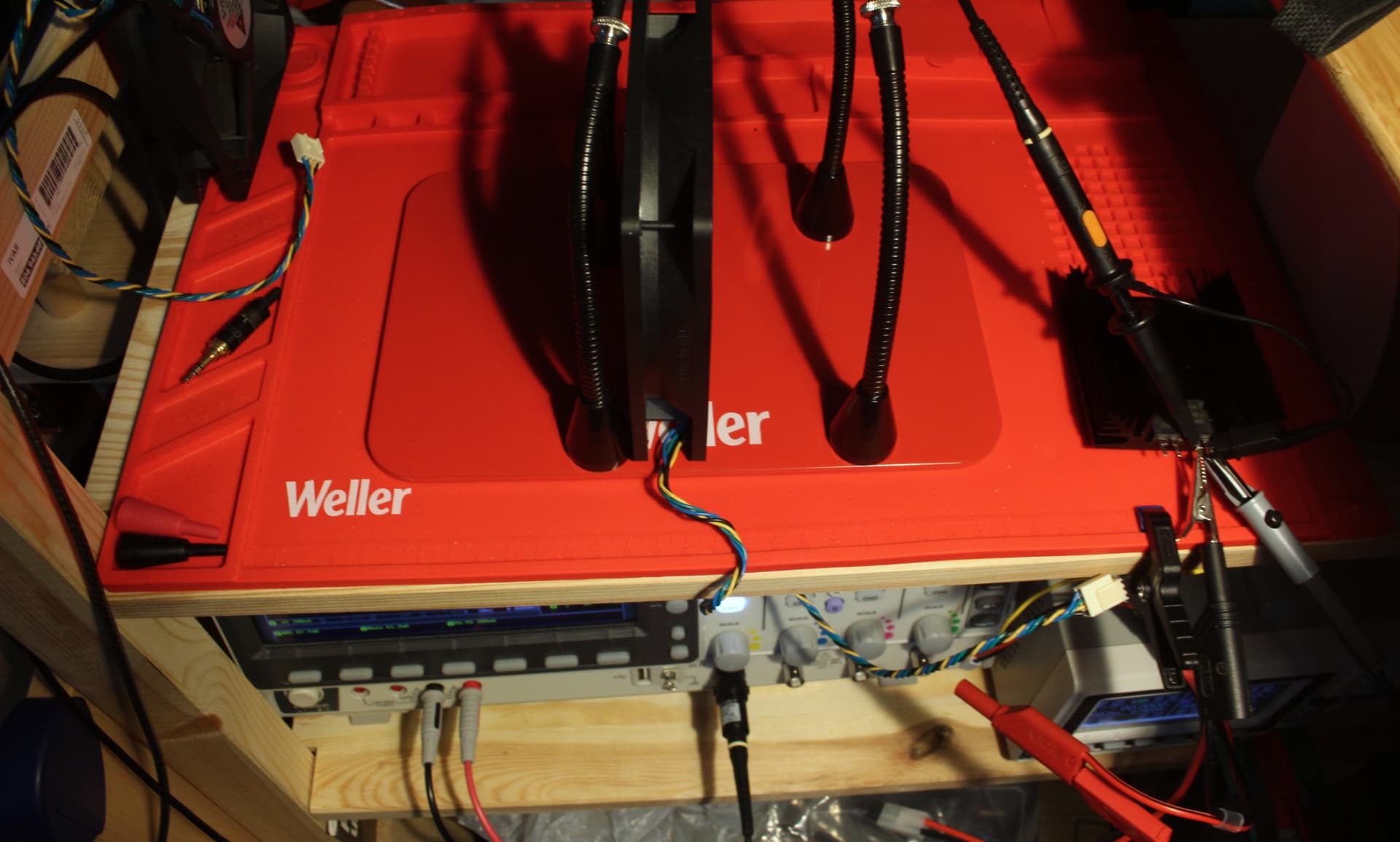
This concludes the wireing for now. Until I get the Powerbox for this setup complete, I will run the lamps of my small bench PSU.
Reasons&Ramblings
The cable being 3 conductors + shield opens up the question why I didn’t run a dedicated conductor per lamp and used the shield as return. Simple answer: I can not solder to aluminium.
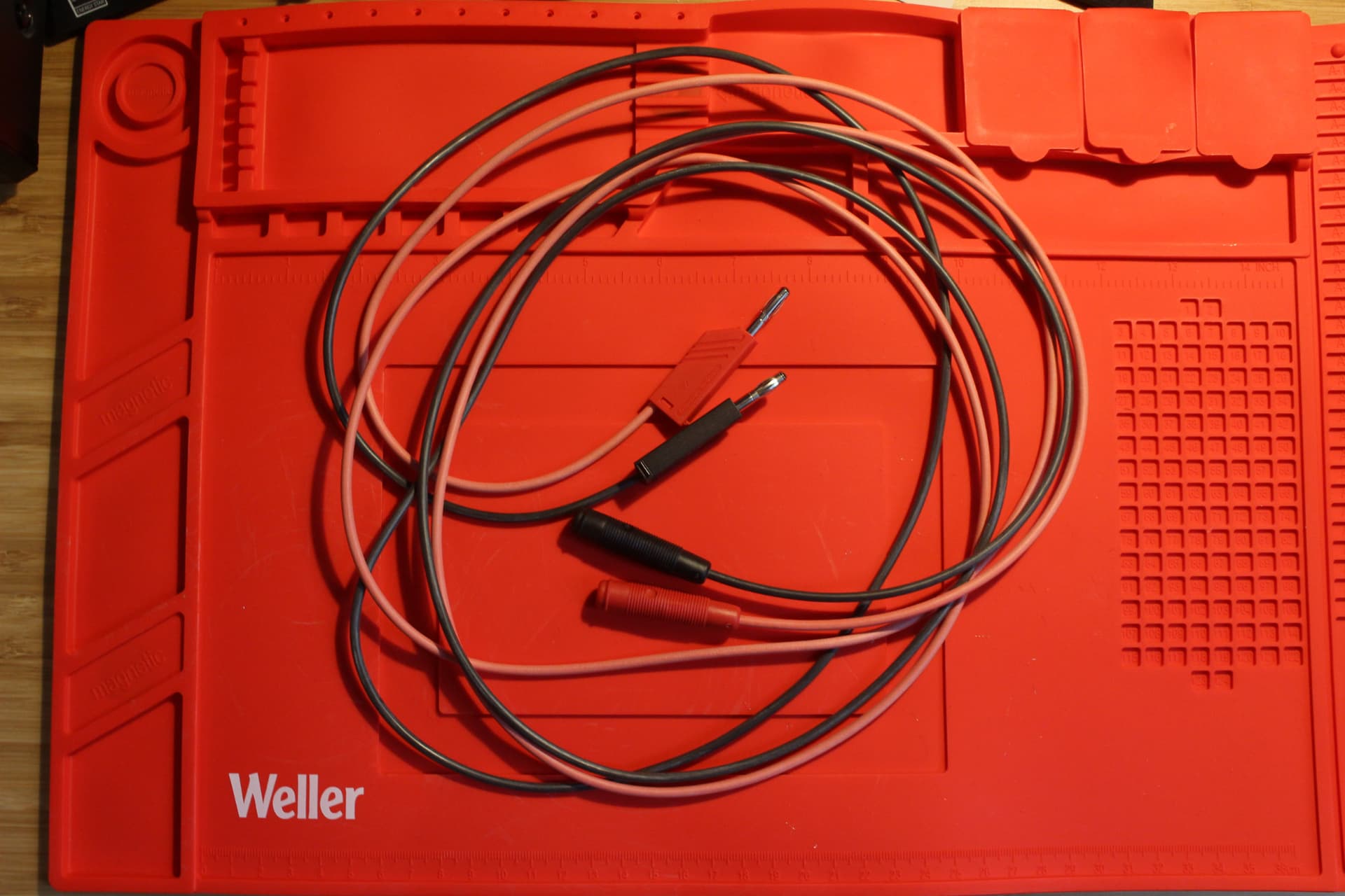
Funny side effect of me running 12V and Fan-header layout: I have probably made the worlds longest fan extension cable here.
Due to a Speadsheet error, the lamps are currently running at 50mA of an allowed 80mA continuous. I may change the 180Ω resistors for 120Ω in the near future.
Easy first:
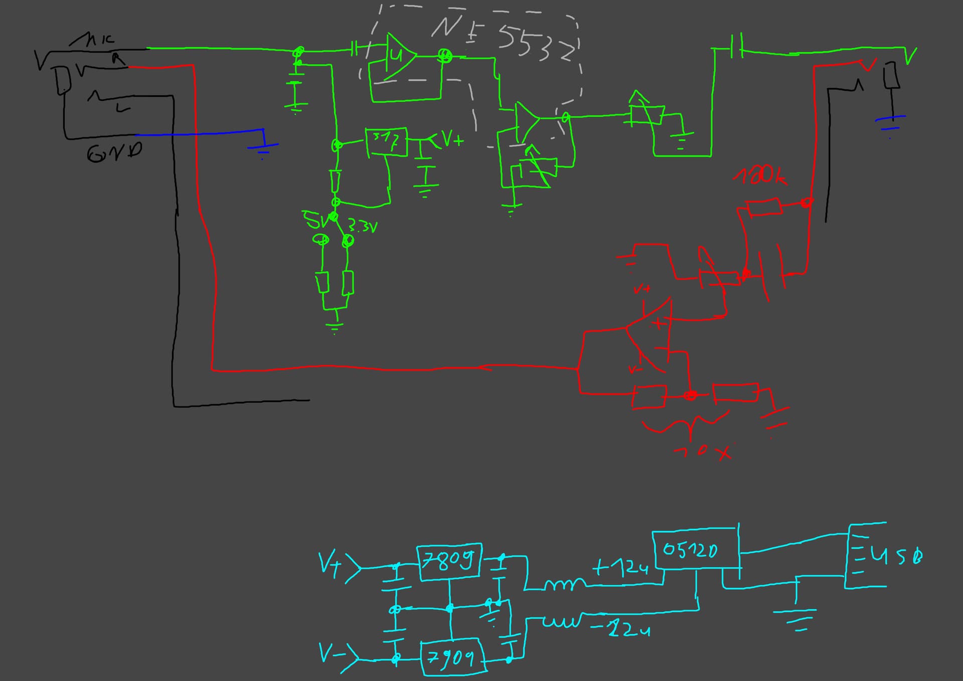
I/O: TRRS jacks for easy connecting, I will likely put TRS jacks in parallel for pure Headphone amp use. USB Mico/Mini/B and likely a barrel jack (5.5x2.1mm) for power in. End of the easy part.
Boosting low-level signals is pretty easy, thanks to the NE5532 Op-Amp. I am going to use half of it as a unity-gain buffer and then boost that using the other half of it. I have seen this set up in cheaper commercial Mic-Preamps, so should work for me too.
To make this not look janky, I will probably stuff this into a Fischer or Hammond enclosure.
The harder parts:
Elektret mics need some bias voltage. Ask 10 people on how much they need and get 11 answers. I personally had good luck with 3.3V and 5V in the past, see here for a successful implementation.
Since I have bias-voltage and a DC-coupled amp section, I need a capacitor (or transformer) to only get the AC (= audio). Again, the internet has n+1 opinions on the type and value of this coupling cap…
Power availability. Since I want this to run of USB 2.0, I am looking at 5V @ 500mA (= 2.5W). Via barrel jack, I could go higher, however nobody wants another power brick.
In case someone here knows what I need to do to pull 900mA the USB 3.1 Gen 1 spec allows, let me know!
The Impossible Guesswork and Prayers part:
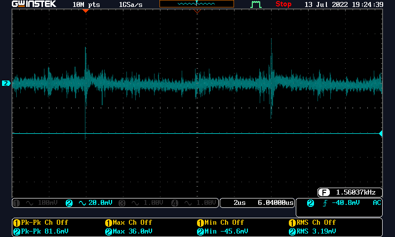
Power. For the Op-Amps to do their work correctly, they need clean power and higher-than-USB 2.0 voltages. My previous experiment with a Traco TBA2 0512 revealed, noise and ripple straight from hell (could add Wifi to make it worse )
So I need decent filtering after it, then linear regulators to get the ripple and voltage droop smoothed out. The light blue part in the scribble above has multiple caps and a pair of inductors in it, not sure if that is enough though!
Audio, for the headphones. I intend to make this easy and just use a single NJM 4580D Op-Amp. These served me well for experiments and projects in the past. The main problem is: I have no idea what the notebook or USB-Dongle throws out. May be ground referenced, may be floating, no clue. How do I make sure this does not go wrong?
Ground and shielding. This will be a nightmare. Since USB is noisy, and potentially running of a laptop (floating) and I need DC-DC boost conversion, I will have multiple ground levels to deal with. Does anyone know what to do here? Just high-impedance DC-path? Or Low-Pass filters connecting all ground levels?
From last time, the Feature list has been more or less met:
USB-Power for 3.2 Gen 1 seems to be 5V at 900mA (= 4.5W). So I decided to bump the DC-DC converter up to a 3W unit (the one in the schematic below is a placeholder). Since my last dance with a DC-DC module, I do not trust their ripple and noise specs anymore. As such, I designed A LOT of filtering in there (filter before DC-DC should be 70 Hz Low-Pass, the one after DC-DC at 230Hz with the choke providing near max impedance at the switching frequency of the converter). Linear regulators after DC-DC because I need the cleanest power!
The Mic-Pre consists of unity gain buffer followed by to-be-tested gain stage and then the output volume pot. Phantom power will be 3.3V (fixed) and adjustable internally.
Added bypass-switch for the internal headphone amp.
I’ve had a quick look over the schematic, looks pretty reasonable. Although… Who in their right mind draws schematics from right to left?!
May I ask what the reasoning behind that is? Why not just use the non-inverting amplifier without the buffer since it already has a high impedance input?
That direction is inherited from the initial scribble. And since the “User interface” is on the left, it is kinda left to right
I don’t know! Please don’t hit me!
No clue. This is my first time handling mic-level inputs. I read over here that the NE5534 may work well for this use. Since part cost is so low, I may just attempt both.
I’m sure the NE5534 is going to work well for this, but there really is no point in adding an additional buffer before the gain stage. I doubt you’re going to notice a difference in practice, but it’s always a good idea to keep the signal path a short as possible, so personally, I would cut it out, but feel free to experiment.