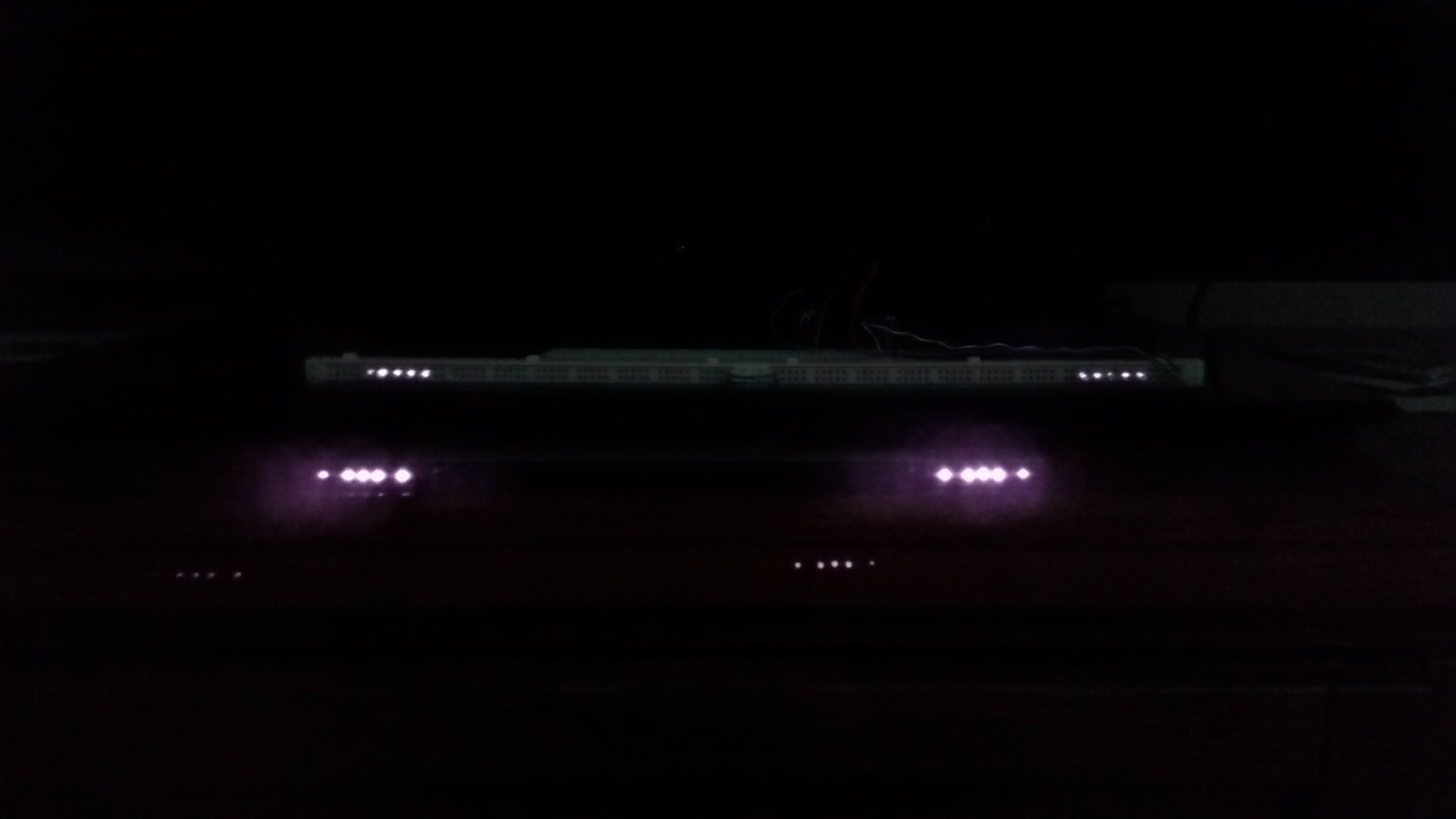
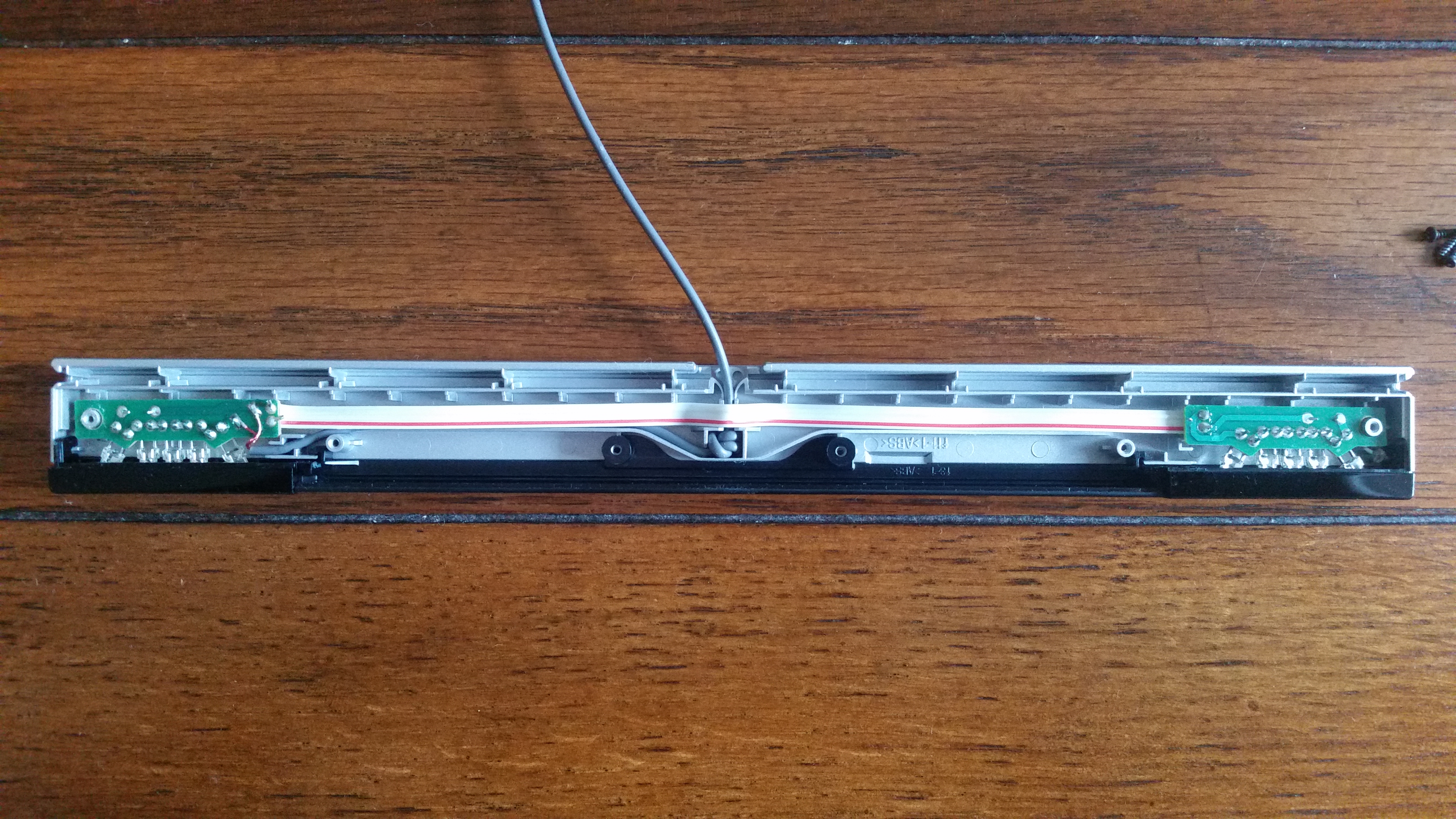
How is everyone? I’ve decided to build my own Wii sensor bar to use with the Dolphin emulator. I am facing a problem with the infrared led output. As you can see from the picture below, the official Wii bar is much brighter than the one I’ve built. The LED specs are as follows: DC 1.5-5V 80mA 0.1W IR 940nm
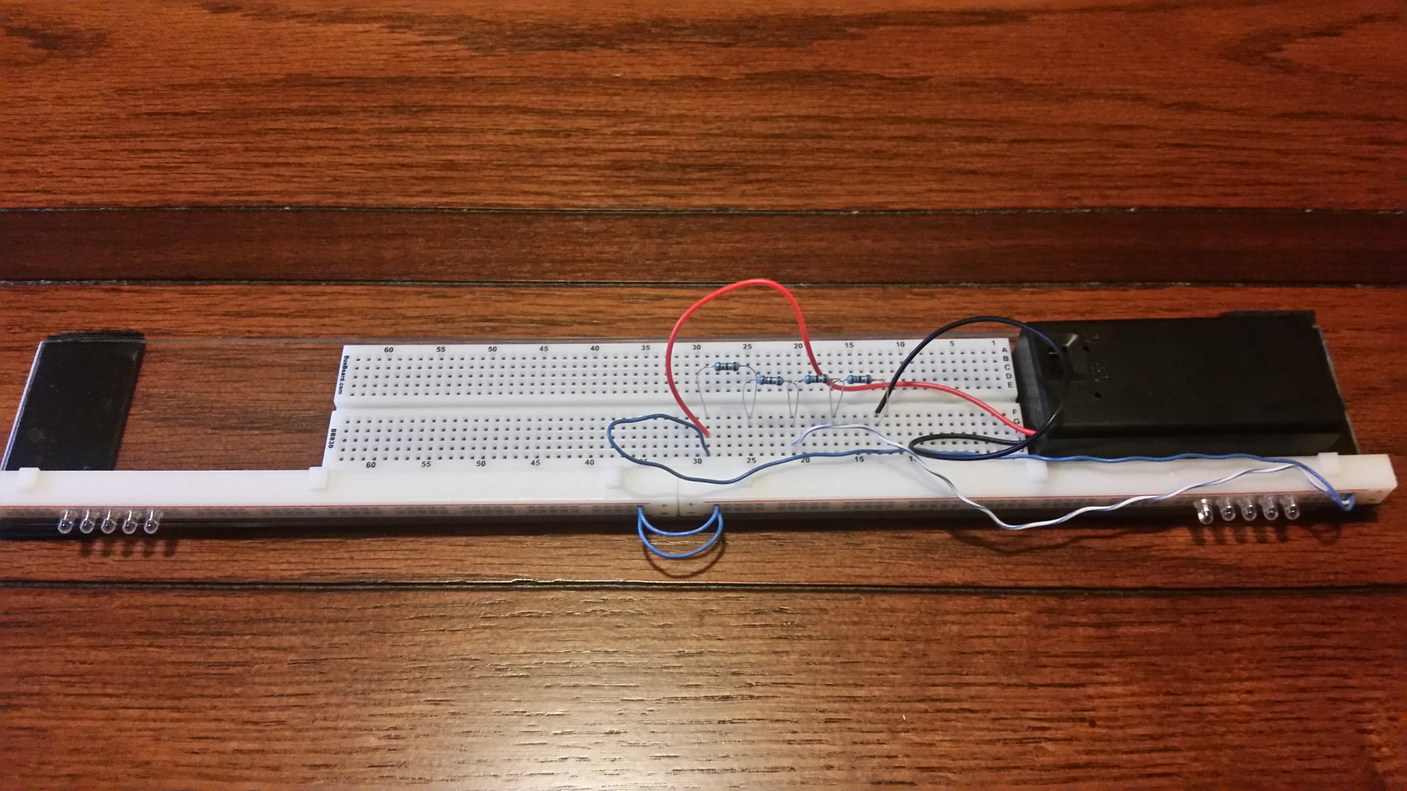
My circuit has 124 ohms of resistance in two locations creating a voltage divide. The LEDs are supplied with 4.5V and the current at approximately 70 mA. The LEDs are ran in parallel.
Is there something wrong with my circuit or is there a more powerful infrared emitter I could use?
70 mA per single LED or 70 per 5-LED cluster? If it’s the second, you’re only getting about 14 mA per LED, which would make it much dimmer than the test current from the spec sheet (80 mA).
Powering an LED from a voltage divider is okay, but usually you just drop a single resistor in series with the LED. The resistor drops some current, the LED drops the rest, and you can measure the current by probing the resistor’s voltage and using I = V/R.
I would test one LED to start, to make they can get as bright as you need. Put it in series with a resistor, maybe around 300 ohms, and see what happens (i.e. check brightness and measure resistor voltage -> LED current). Then step down the resistance until you get the brightness you’re looking for, and keep an eye on current. Your LEDs are rated for 5V, so you can probably connect them directly across your 4.5V supply without them burning out, but work your way there slowly. Add a second LED in parallel to the first, and see if anything changes.
I’m being cryptic. Just use one resistor, and you probably need a smaller one. Fun fact, you can put two resistors in parallel if you run out of smaller-value resistors.
Ok, some quick theory: Ohm’s law stipulates that U = RI. Changing this equation around, we get that I = U / R and the resistance necessary is R = U / I. Given this, the lower your resistance the higher your current will be.
Now, you usually power an LED in a series, like this:
||-----R---->----|=
Where || is your power source, R is a resistor, > is your diode and |= is your ground. for the diodes, the current will stay the same while the voltage will drop by around 0.7 V per diode. But the resistor will drive the diode(s).
Since you need ten diodes in total, I would connect them like this:
Do note I do not know the correct mA for your diodes, make sure to doublecheck so you do not burn them out. Also, the circuit above will draw 2*0.08 mA. Just a heads up.
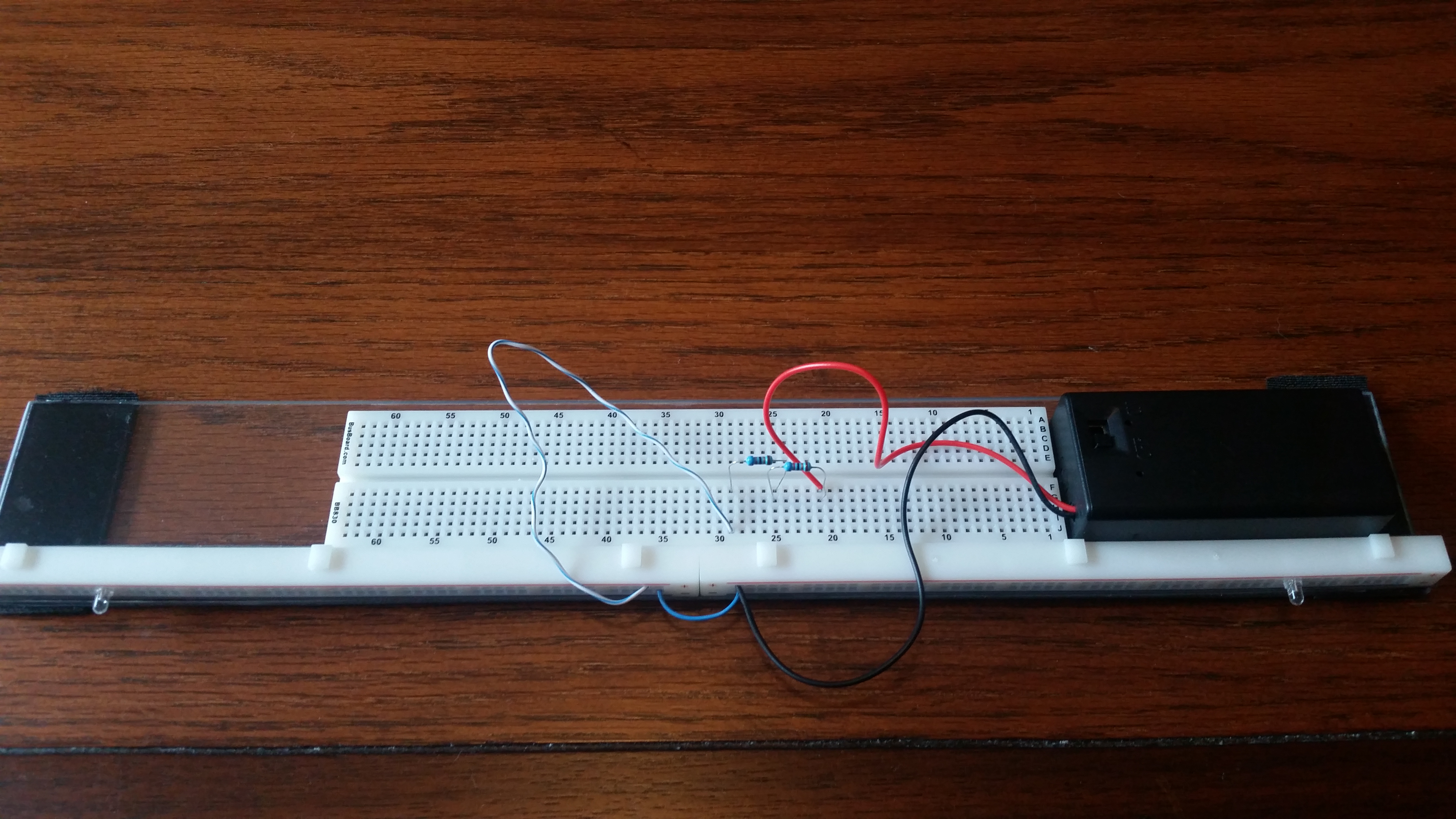
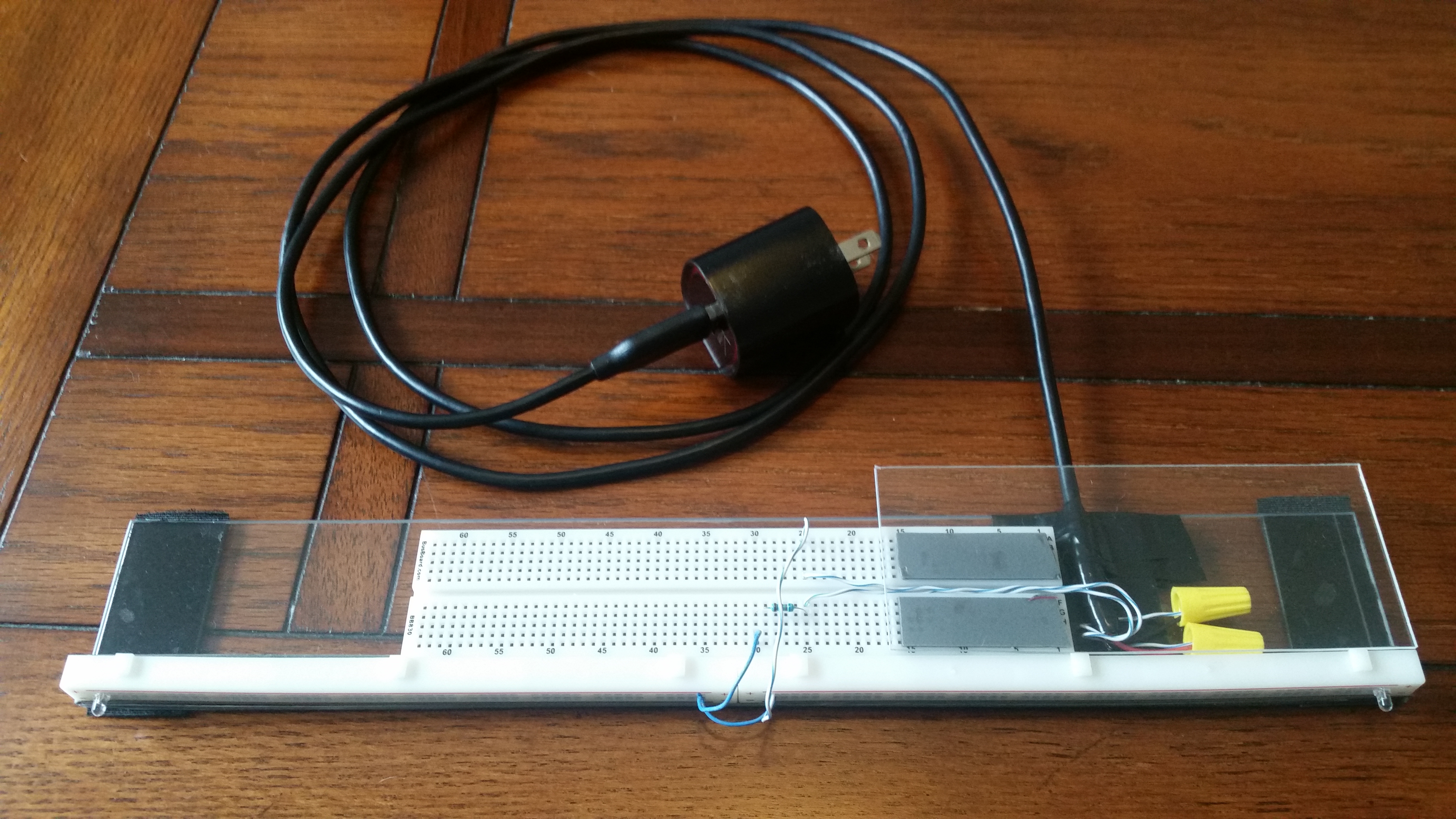
Think I’ve made some progress. Instead of running 10 LEDs in parallel I have 2 in series. The Wiimote is still a bit choppy but is picked up at 12 feet unlike before. I would try adding more in series if I wasn’t using the power rails to hold them I also think I need a larger resistor to dissipate the heat. The LEDs are receiving 9 volts, but I think only the current would harm them. Right now the current should be at:
If your TV has USB ports, you could use those to power your circuit. It will provide you with up to 500 mA of power, which should be more than enough. Use something like this (should be available at your local electronics store):
As for your other problem, it should be possible to use styrofoam, just make sure the pins to your LEDs are touching properly. If you have access to a 3D printer, the next step is to print a plastic case, I suggest FreeCAD for creating the case. If not, see if you have a local maker space available. Good luck!
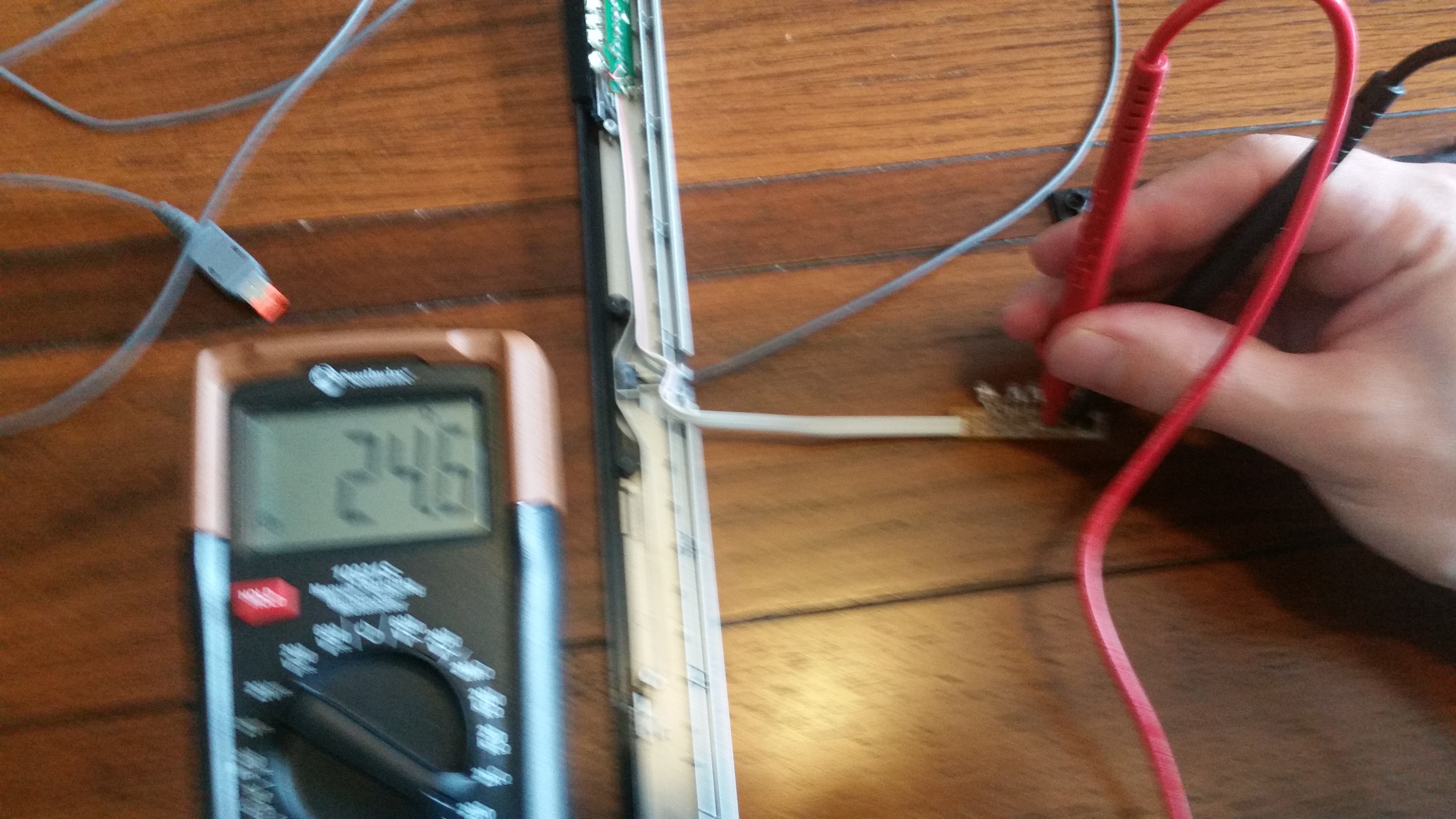
Each resistor is rated at about 24.5 Ohms. I assume there are 5 volts being supplied so these are provably 200 mA LEDs or 100 mA. I’m not sure what happens when the positive splits in two directions. Perhaps the voltage is lower. ¯_(ツ)_/¯