[Build log] うずめ X コンパ | A Dreamcast & a Gamecube PC

Body work finished. I’m happy of having done that, brought back the Dreamcast spirit to the build.

And the standoff are glued down, final position of the MOBO.

Look at that clearance :grin:

Finally, I decided I will paint matte white again, but I will be patient this time and choosing a good spray paint this time. But will have have to wait for a day that is not too humid… (might take some time).

Also I was ready to retrobright (thanks to @GigaBusterEXE for lettign me know about that) the grey parts, using the sun for it’s UVs, but it hided itself behind the clouds the whole afternoon…

8 Likes

Did the retrobright. After 2 hours, the result is good. There is still a light hint of yellow on the controller faceplate, but that is surely because it was hot today, increasing the rate by which the peroxide broke down in water and O2, and making it less effective.

Before and after:


Before and after:


8 Likes

Was able to do a first coat of paint today of white. Will do a clear coat not before two days, but anyway next week will be pretty much rainy so I hope I would be able to do the clear coat next week-end.


Also began to work on mounting the connector board to the connector plate. Hit glued standoff and drilled the PCB to screw it down, so I can easily remove it if needed. Will use pin headers to connect the logic board with the controller board to have something compact.


13 Likes

Progressed a little bit with the build. Done the clear coat yesterday. And now there is still a slight yellow hue, so it’s clear coat that do that. Note to myself, never paint a project primarily white next time.

Also, a little lack of insight, but had to sand down a little bit the button holes so the buttons could move freely. Thought about that, but didn’t not put tape prior to painting.


Speaking of tight clearances, well now the extension piece is stuck with the bottom piece. Wanted to test fit, had to jam it a little it, and now I’m unable to remove it. But not a big deal, just gonna jam at some point an antenna inside by the hole. And the little pieces have been added back.


And installed the intake fan. Had the 50mm fractal fan, didn’t want to buy a 40mm one, and realized I didn’t need the mounting holes, so I removed them. And then trusty hot glue to install the fan and manage its cable.

8 Likes

Uzume is partially completed! So I made big strides in the project, because I was eager to have it assembled. Had ideas of how to do different things that I like that I come up with as it made the build more thoughtful and less “hot glue everywhere”.

First, I use the original screwing hole to mount the power button in the Dreamcast, for, well, mounting at the same location a power button. Use a leftover plastic piece to carve out a retaining piece for the power button. Could have left like that, but I also added some hot glue to make sure everything is secured. Also, fill the inside of the plastic shell of the power button to make sure the switch can push back adequately after it’s pressed down.

Second, I shorten the light diffuser assemble so it would fit even with the controller port board in the way. Made two small holes in the pcb of the controller port board to install the led. The led sit flush with the light diffuser when the top part is installed.


I forgot to take a picture of it, but because the extension part is stuck with the bottom piece, and as there is one of the screws that requires the extension to be removed to screwed in/out, I drilled an hole in order to have access to that hole and be able to screw all 4 posts.

Also, did a small extension for the the CPU fan, and mounted the back “plate” io (aka cutted metal mesh), and used an unused wifi antenna to glue the pcb part inside the extension hole.

Everything mounted down and working.

And fully assembled and working fabulously.

There is only work to be done in order to make the controller ports functional. I intend to solder headers to the controller port board and the pins to the logic board so I can neatly assemble it compact. But I need to acquire a proper iron, and I don’t feel like being frustrated soldering, so that will wait a little bit.

Also, I’m waiting for a sticker for the front logo.

Performance wise, there is no difference really between the open air system and inside the shell either with lid close or open. Same 1089 score on Time Spy.

Lid close:

Lid open (I forgot to screenshot the score, but it 1089) :

14 Likes

It looks fabulous! Awesome job.

4 Likes

The controller ports work!*
*(Well only the 3rd and 4th because I damaged traces last weekend, would need to buy a new one)

Despite not having the appropriate pin headers (had on hands some with a 2.5mm pitch, but none with a 2mm pitch) I still went ahead and solder everything together. It works (when the adapter is recognized as a Mayflash one, and not as a pokken controller …) and suprisingly everything fit inside.

Sure if I do any commission (I hope I will have some) I will obviously use 2mm pitch pin headers, and properly mounted through the holes. But as I kinda abused that particular adapter and botched a previous repair on them, I was not able to remove solder in the holes. Maybe I will contact Mayflash to have the boards, but without any wires soldered.

Had to remove all the sheathing on the usb plug to make it fit. Next time I will just get a usb header to solder instead.

Played Wind Waker on a Dreamcast :crazy_face: And did a little wink to the original inspiration :wink:

I will post the sexy pictures when I will received stickers of Uzume logo to put in the front for the final touch.

10 Likes

Sexy pics: (Not sure I will keep the sticker however)


8 Likes

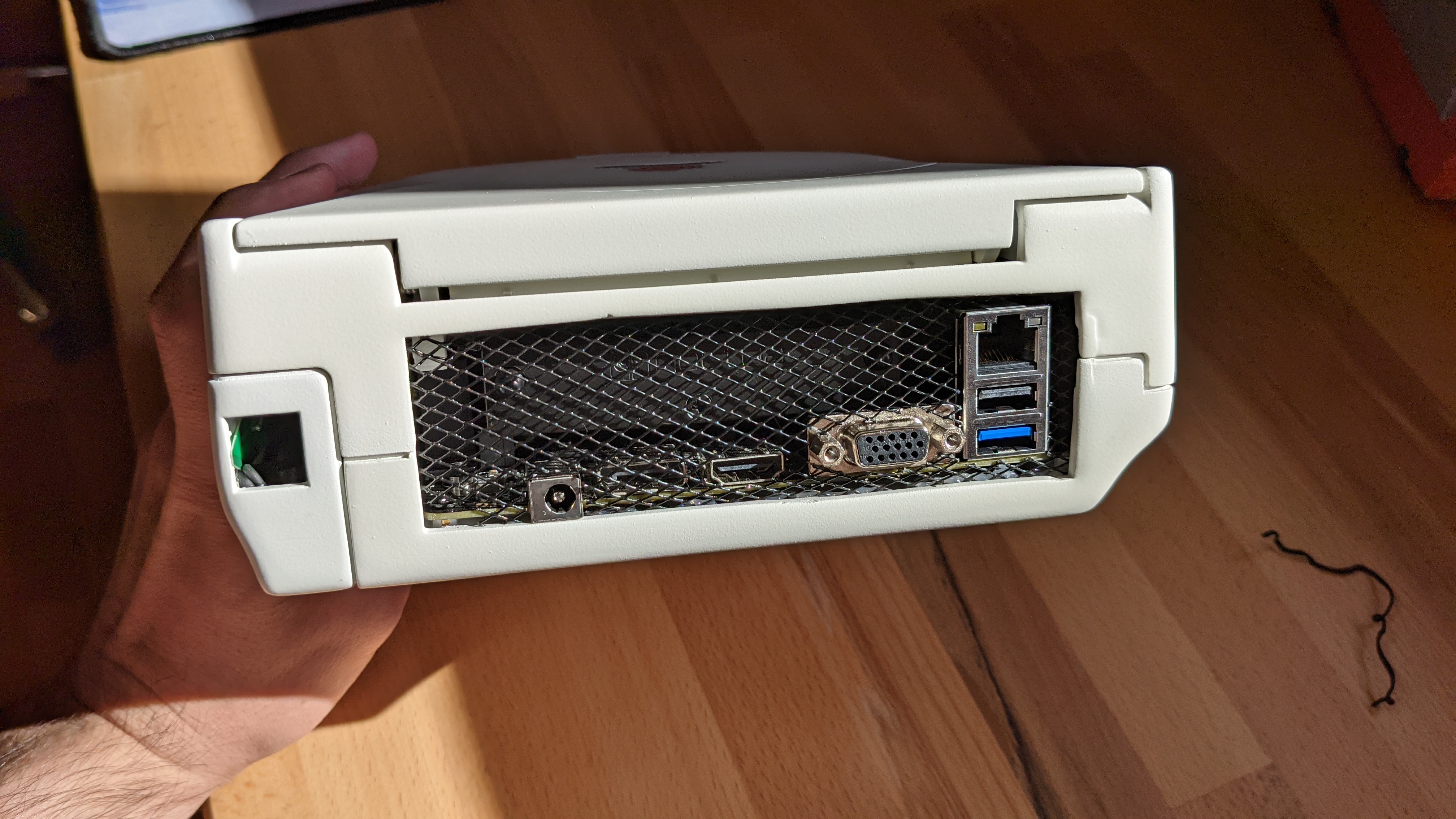
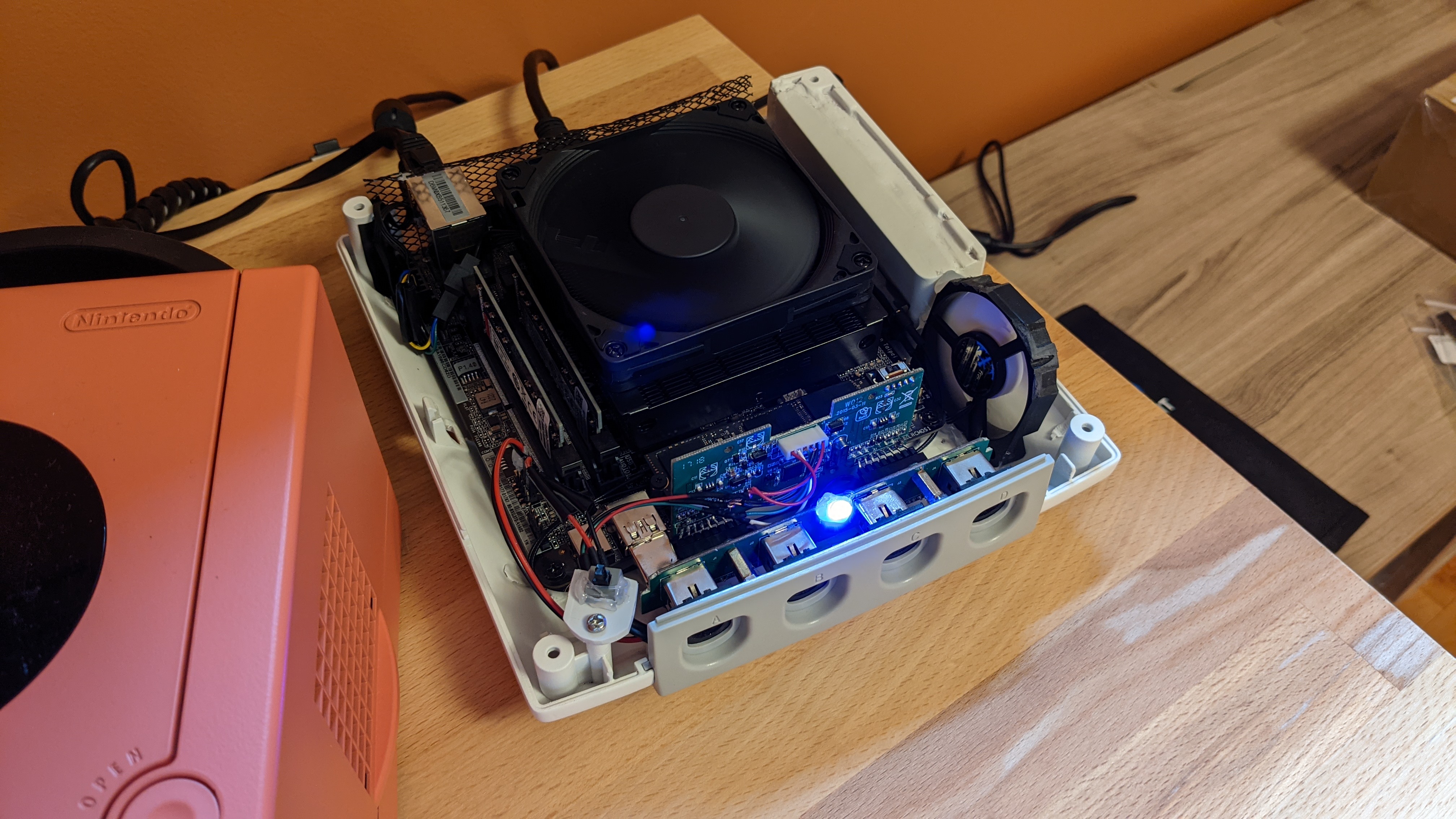
Out of boredom, I’m now beginning to thinker with the idea to power the Gamecube with USB C cables. Not sure if that idea will fleshed out with my current PC, or if it will happen in an eventual Gamecube v2. Anyway, I’m beginning the thought process here as it will eventually involved new learnings, such as step-down conversion and PCB making.

“PCB making? What are you saying?” Hold with me here. First, my idea is to use one of those few 200W USB C GaN charger with two ports providing up to 100W (or maybe just two 100W GaN chargers) to provide up to 100W to the PN50, and to the GPU, independently.

If you follow a little bit the news around USB standards, you might wander why I don’t wait for the USB PD Revision 3.1 to land, which would allow up to 240W with a single cable. Although it will be an interesting idea, the spec would be able to obtain those wattage with the use of voltages up to 48V. This would require me afterward to step down the current twice, one time to 19V for the PN50, and one time to 12V for the GPU, which might be space consuming to do.

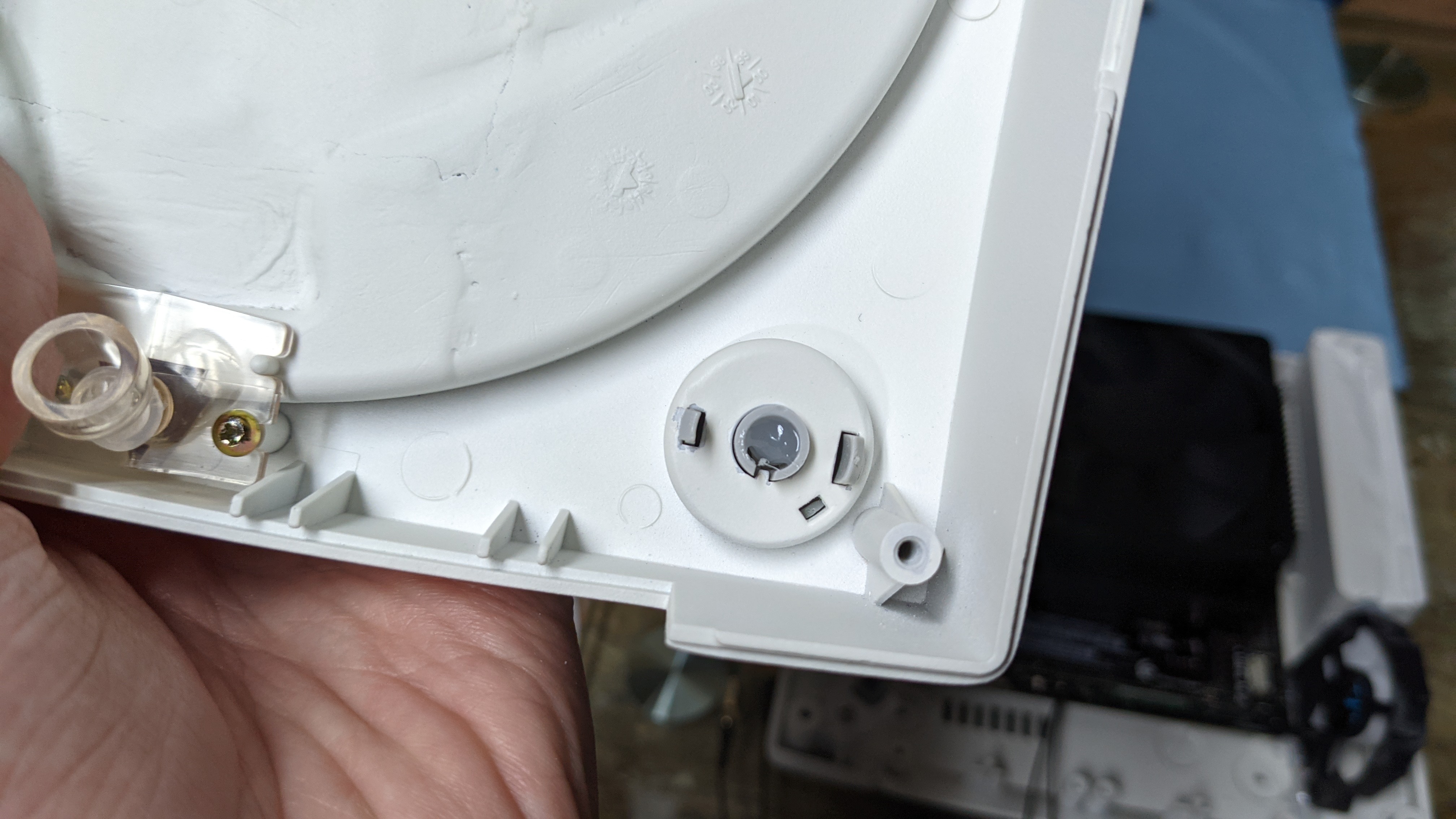
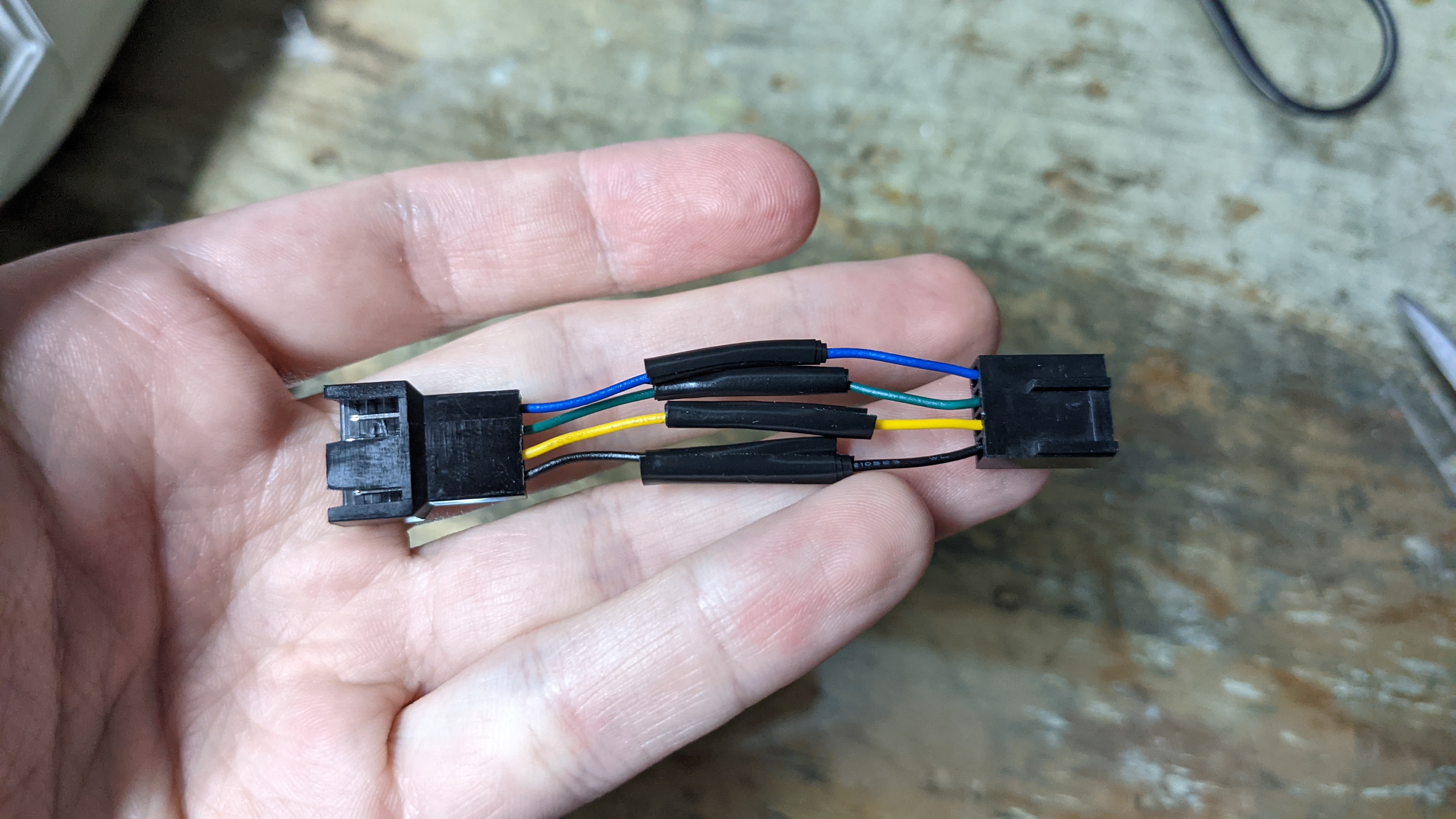
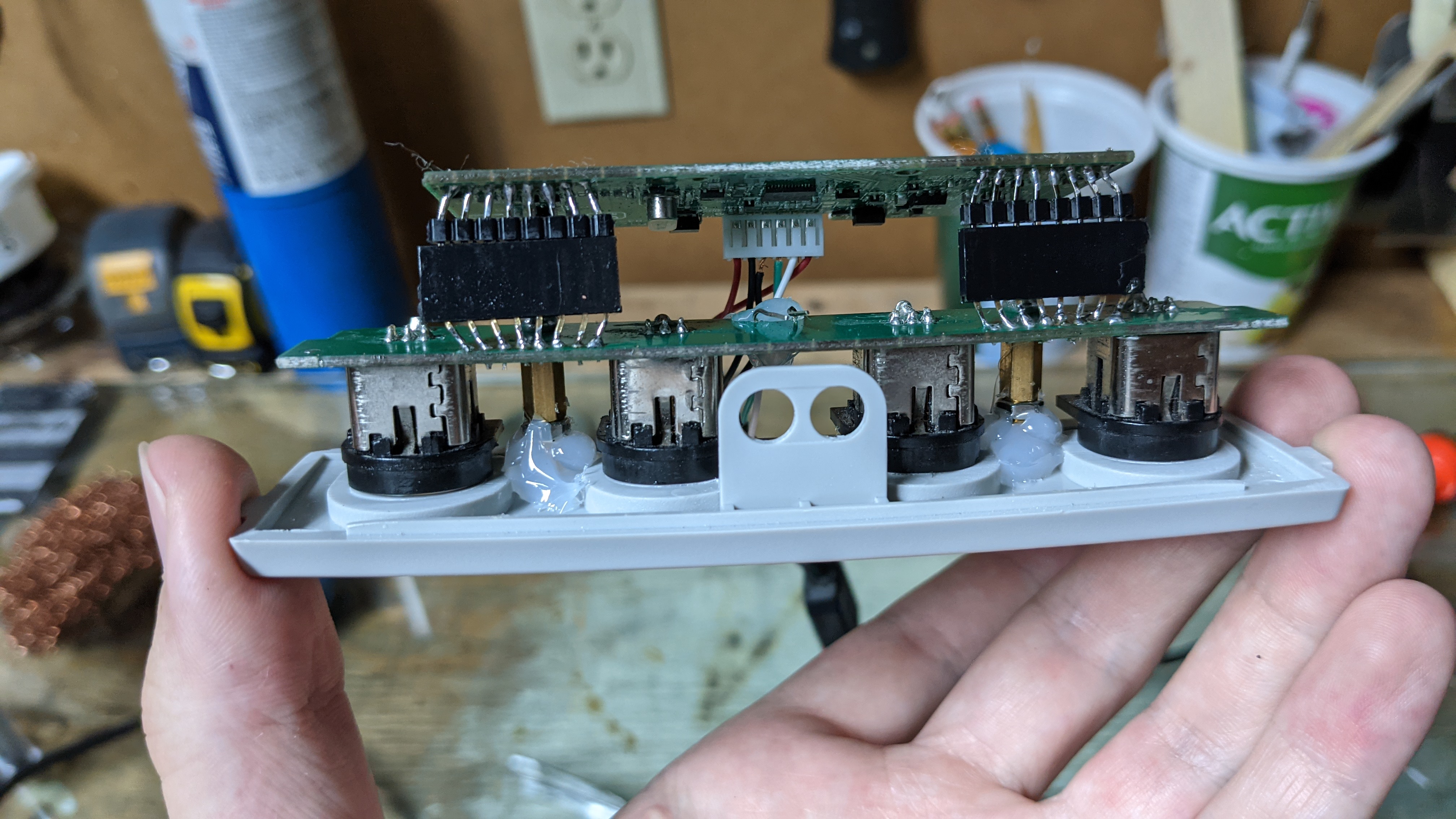
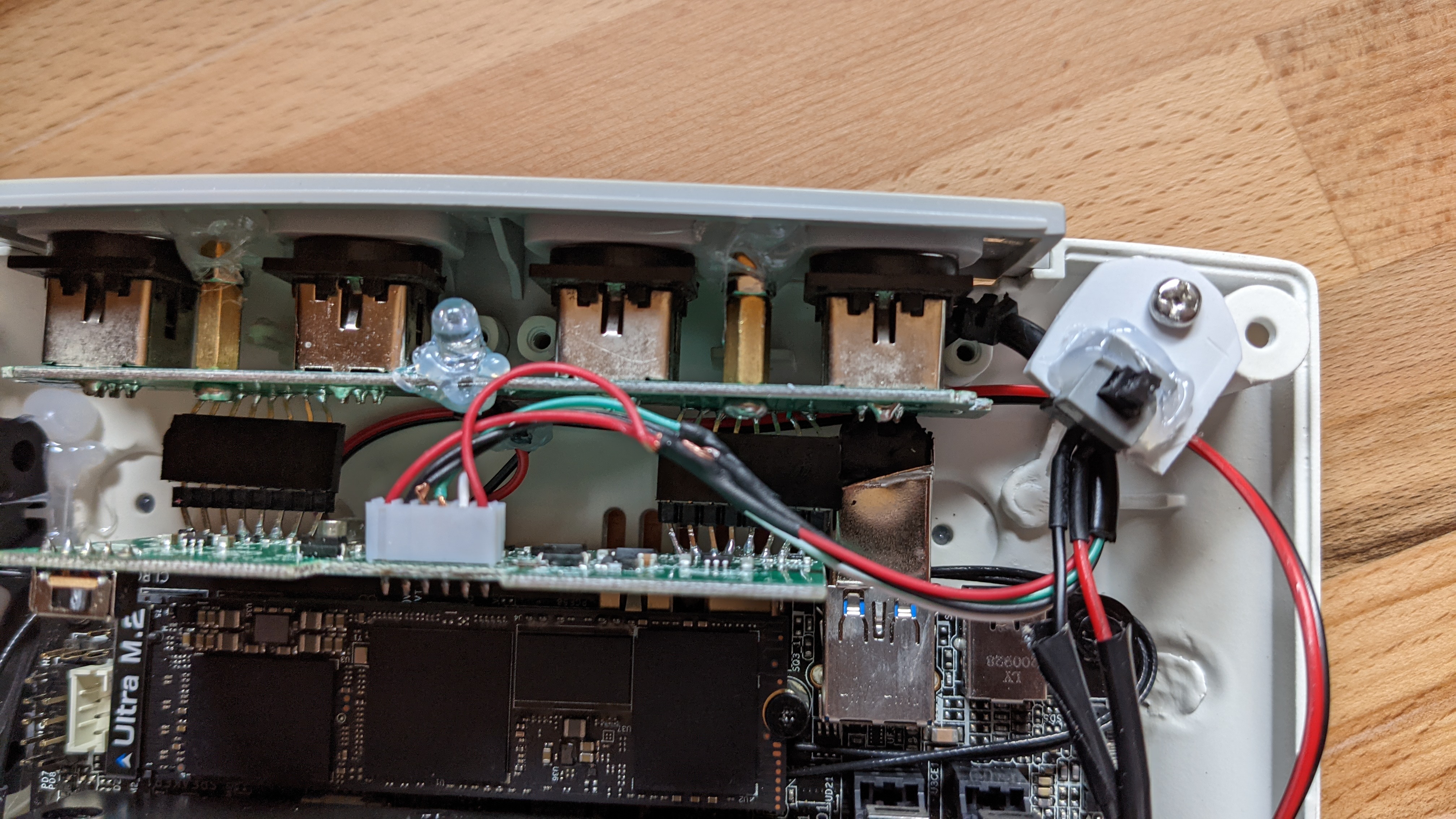
Therefore, the idea is to use two USB C cables, and to use those nifty USB PD handshake module to ask for 20V charging. However, ideally I would like not risking to solder something on the PN50, so using instead a PN51-S1 (or a future PN52S) which accepts power delivery on the rear USB C is an idea I’m considering.

Staying on 12V as of right now is not the best experience on the long term, as 12V power bricks are rare (and bulky), and powering the PN50 with 12V do bring a performance hit, although it doesn’t really affect me in my use.

“Ok but what does PCB making has to do with all that?” Here’s the fun part. It’s part of a greater idea to make a tighter, more professional Gamecube PC with an eventual v2. With the USB C power delivery, I will be dealing with 20V. No problem for the PN51 as it deals usually with 19V and feeding it 20V will probably be a non-issue.

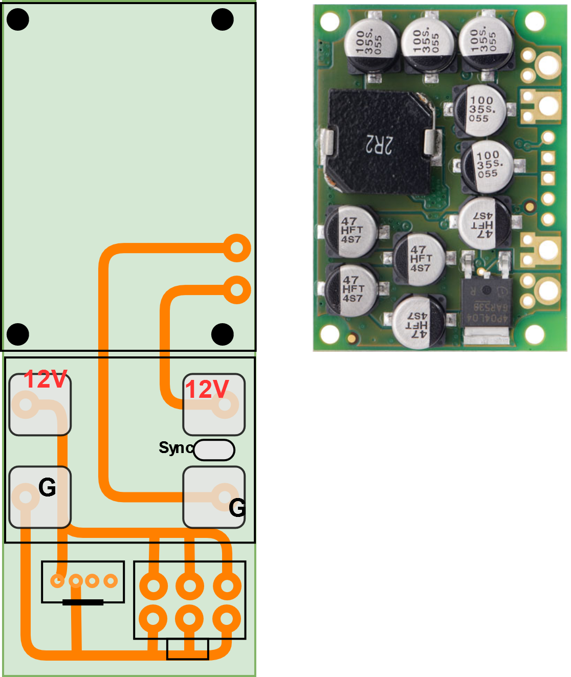
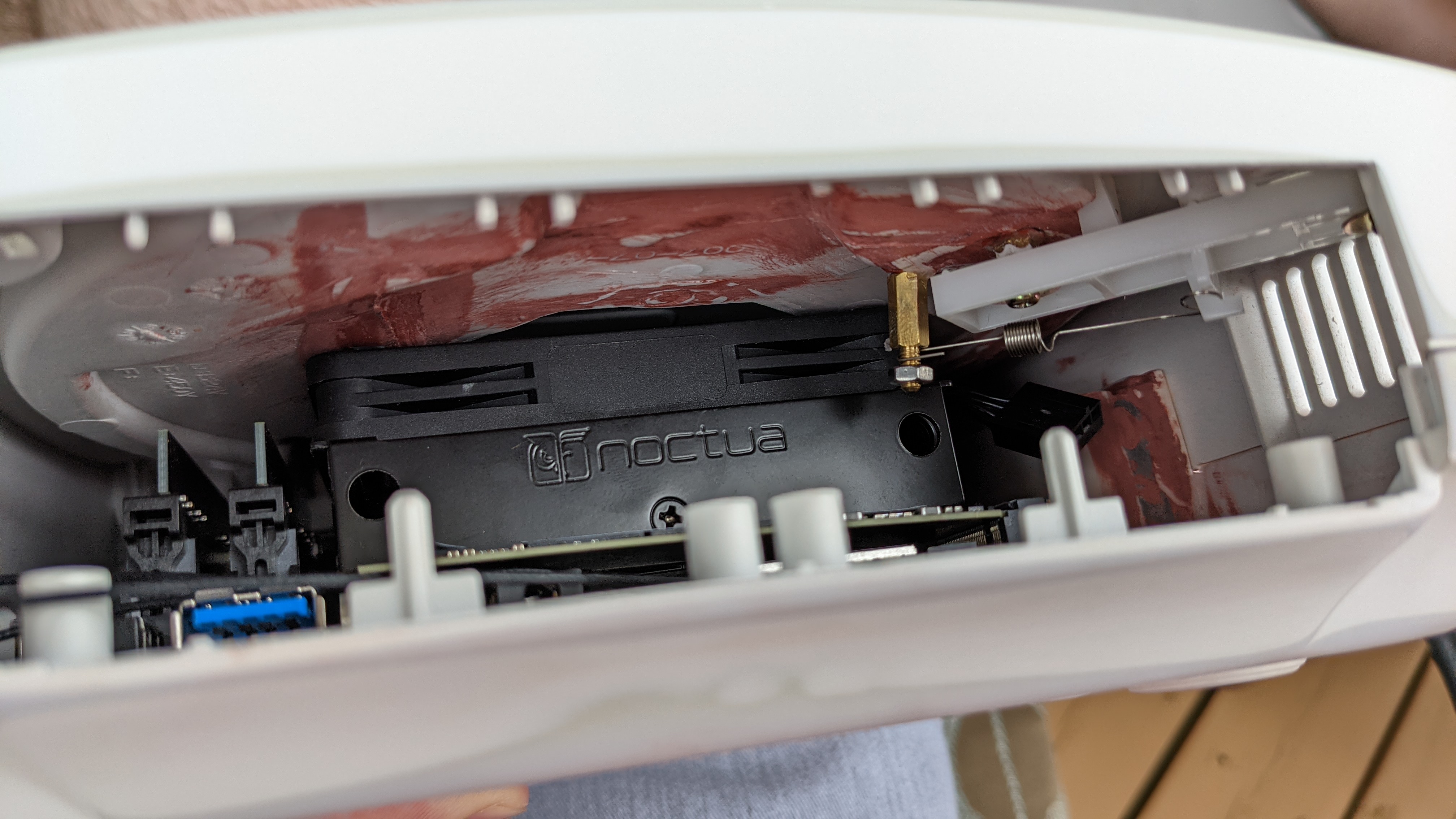
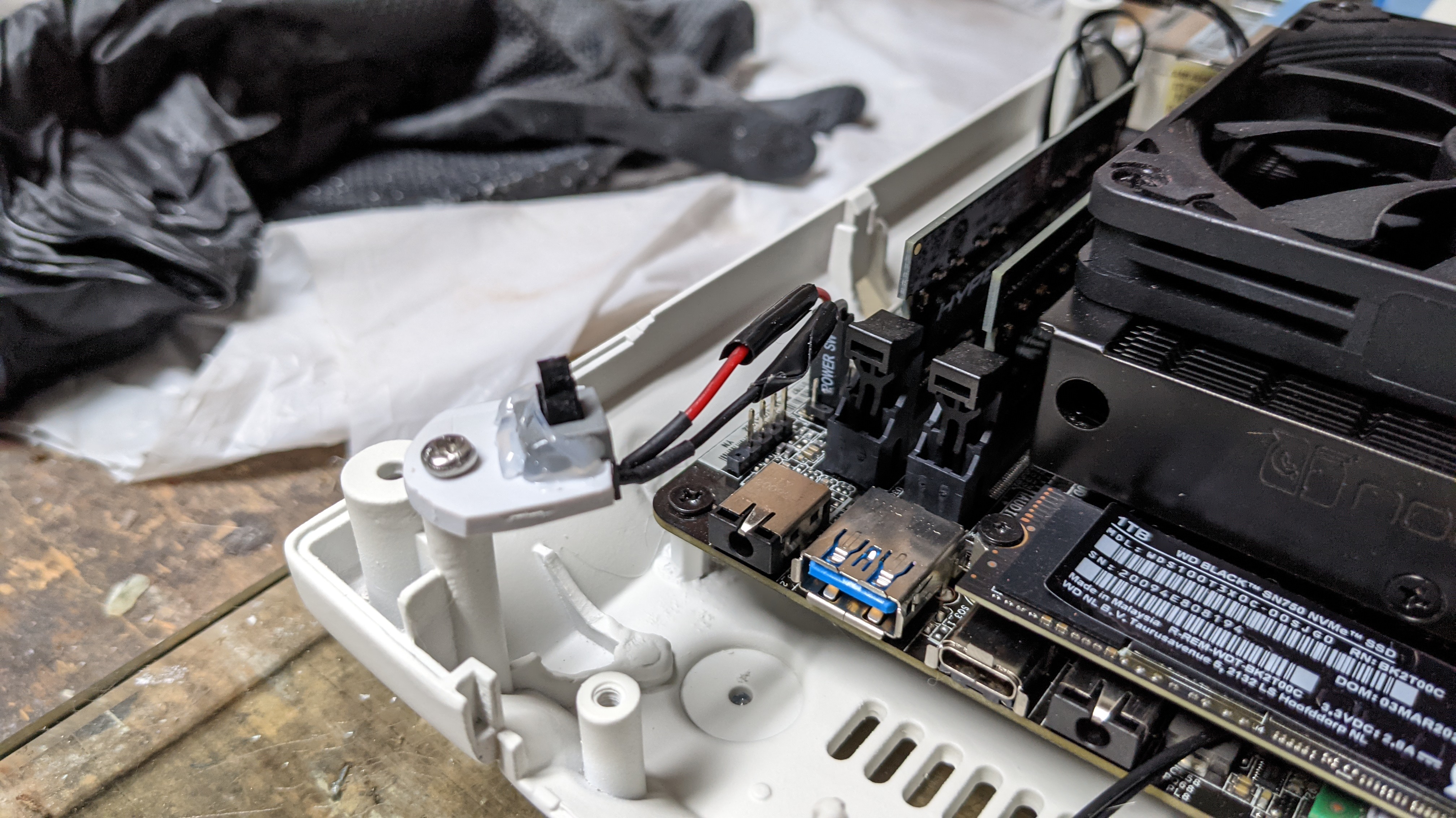
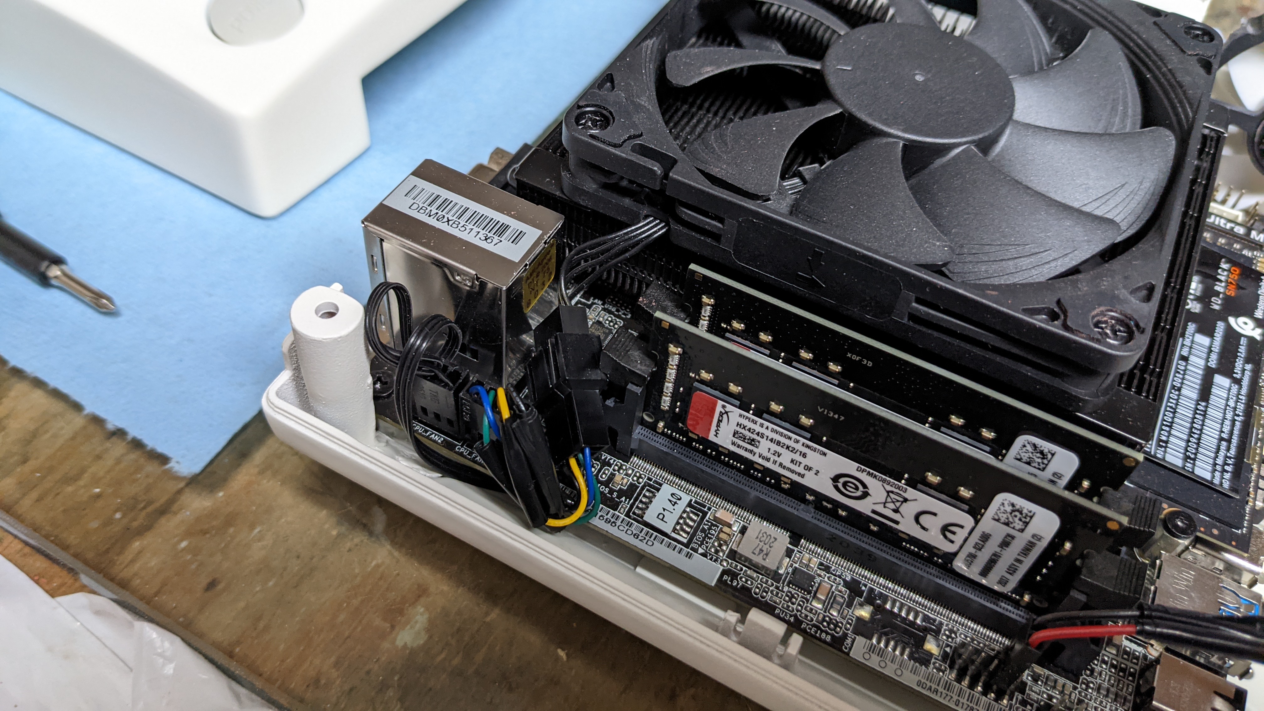
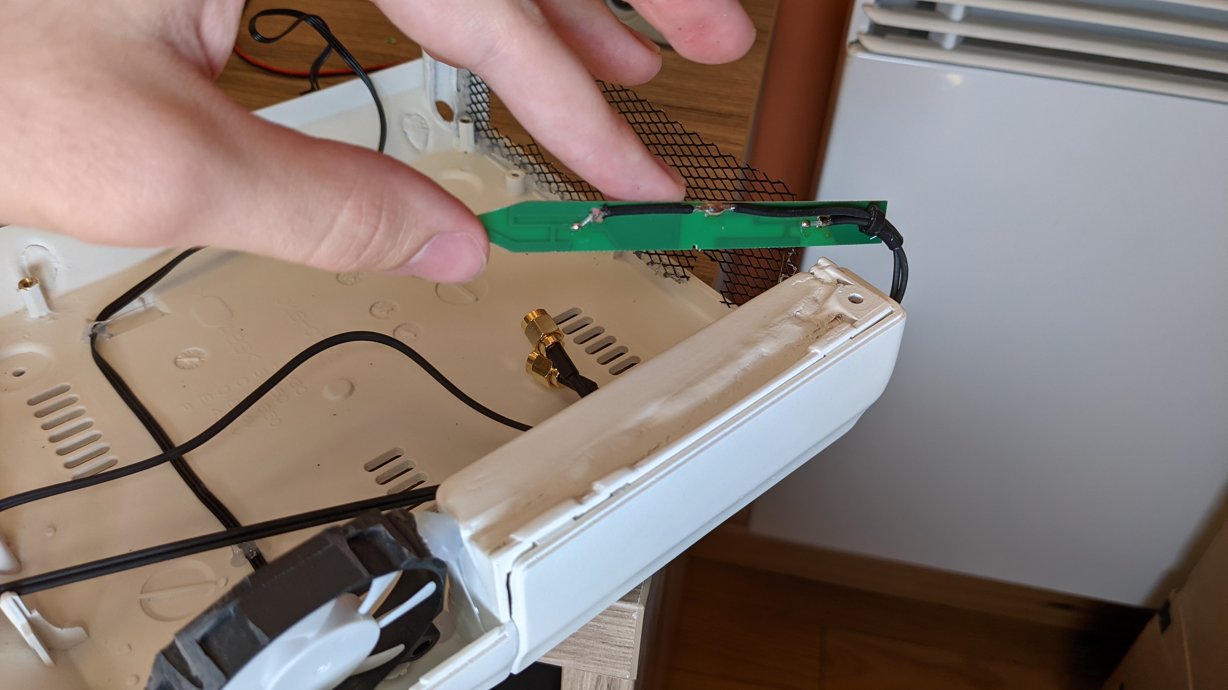
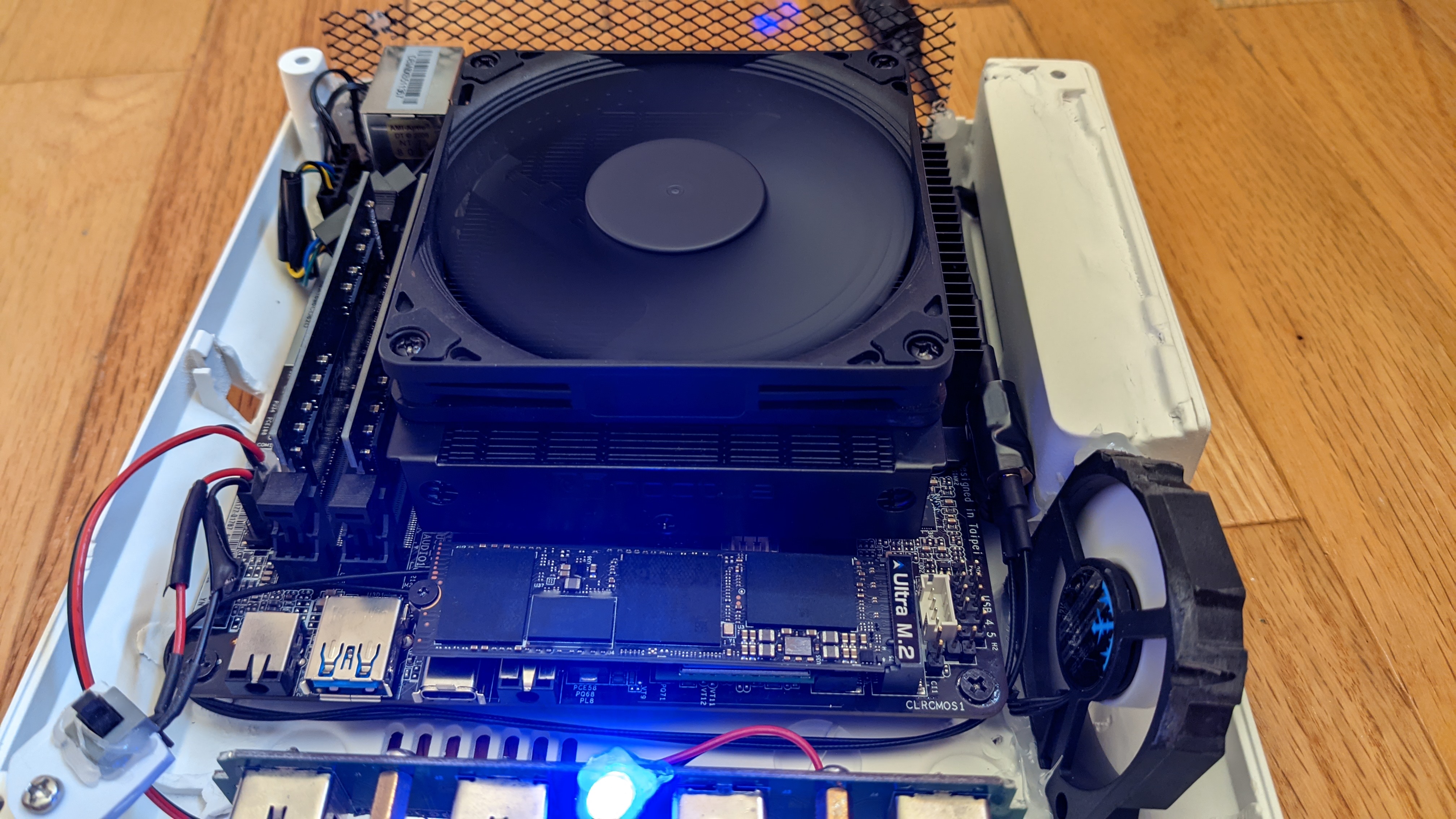
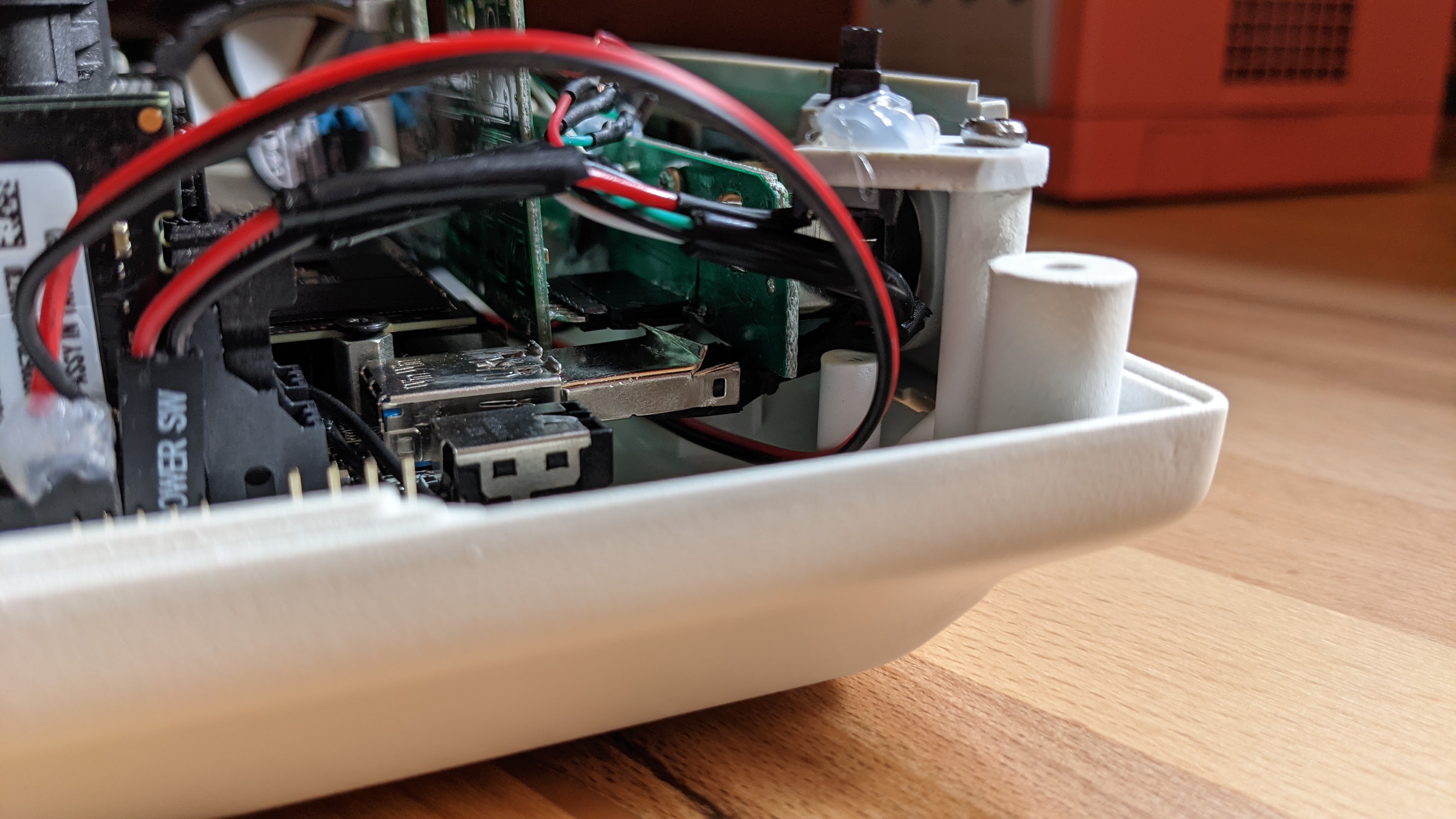
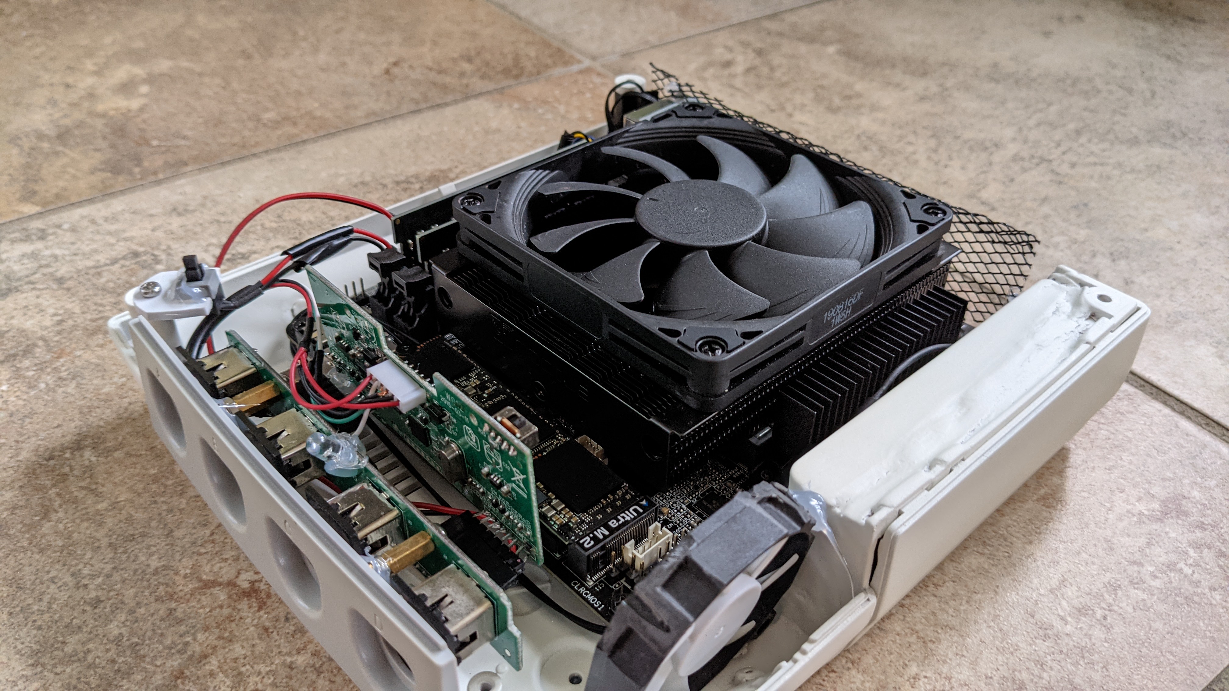
However, I need to step-down the “up to” 20V 5A down to 12V 8A for the GPU (I’m keeping my option open to power a 90W TDP GPU, like maybe an eventual 3050?). I cannot ask the USB PD module to ask that kind of current, as USB PD specs cap out the 12V delivery at 3A. Plus, I need to use a something like the GxR-DIY to switch the power on or off depending of the power state of the PN50.

With those limitations and consideration, I’m actually tinkering about designing a PCB to have a tidy power delivery thingy for the GPU.

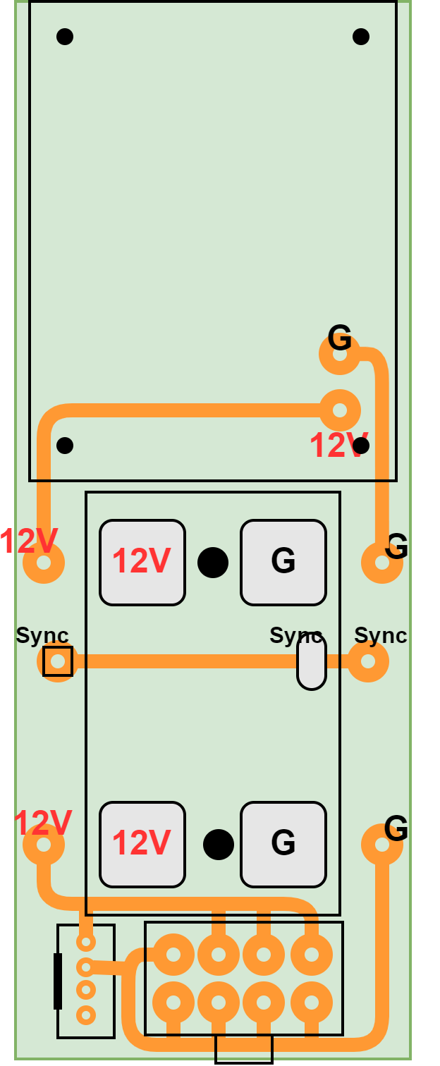
I would solder to it a 12V, 15A Step-Down Voltage Regulator to step down the 20V to a 12V, and I would solder the GxR-DIY to it for the power switch. Plus I would put on the PCB a 8 in GPU socket to power any eventual GPUs, and a 4 pins molex header to power the NVME to PCIE riser. Also, it would have the pin on it to sync with the PN50. The traces on the PCB would be 5mm wide to be sure they can deal with a current up to 8A, judging by this table.

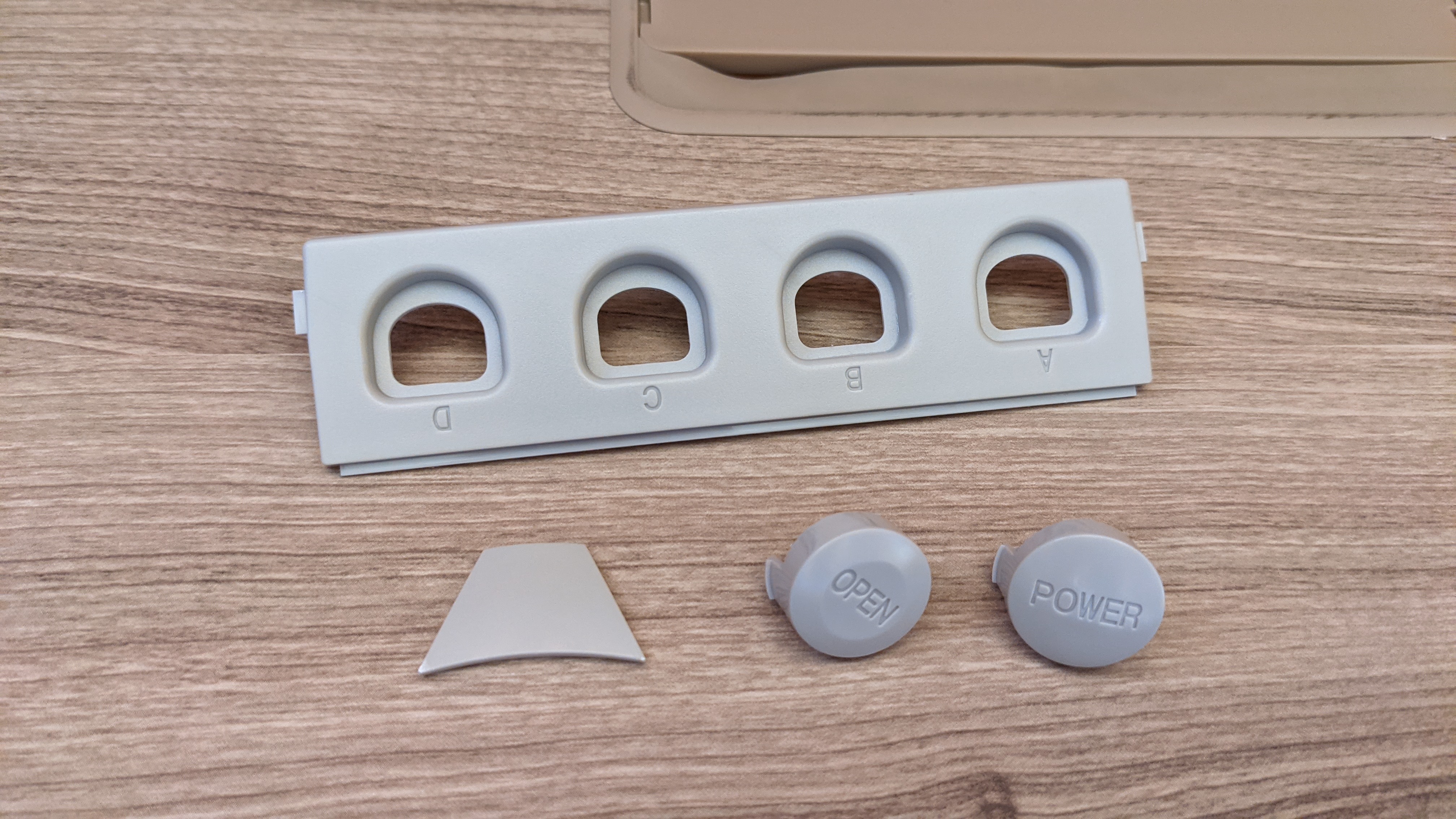
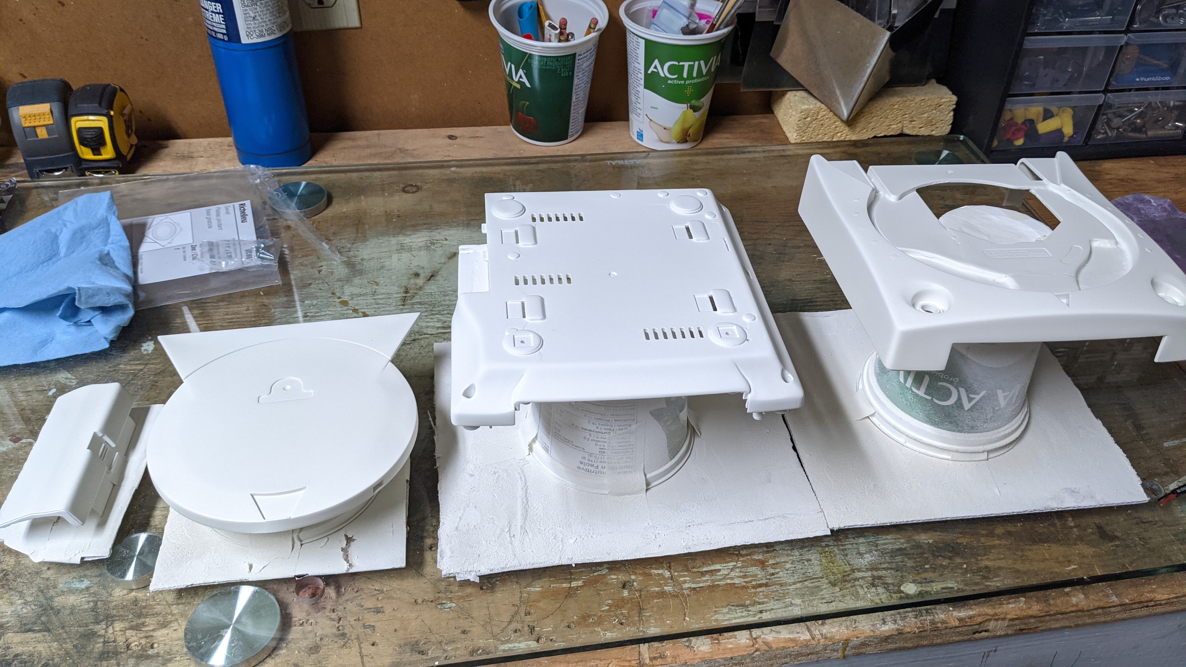
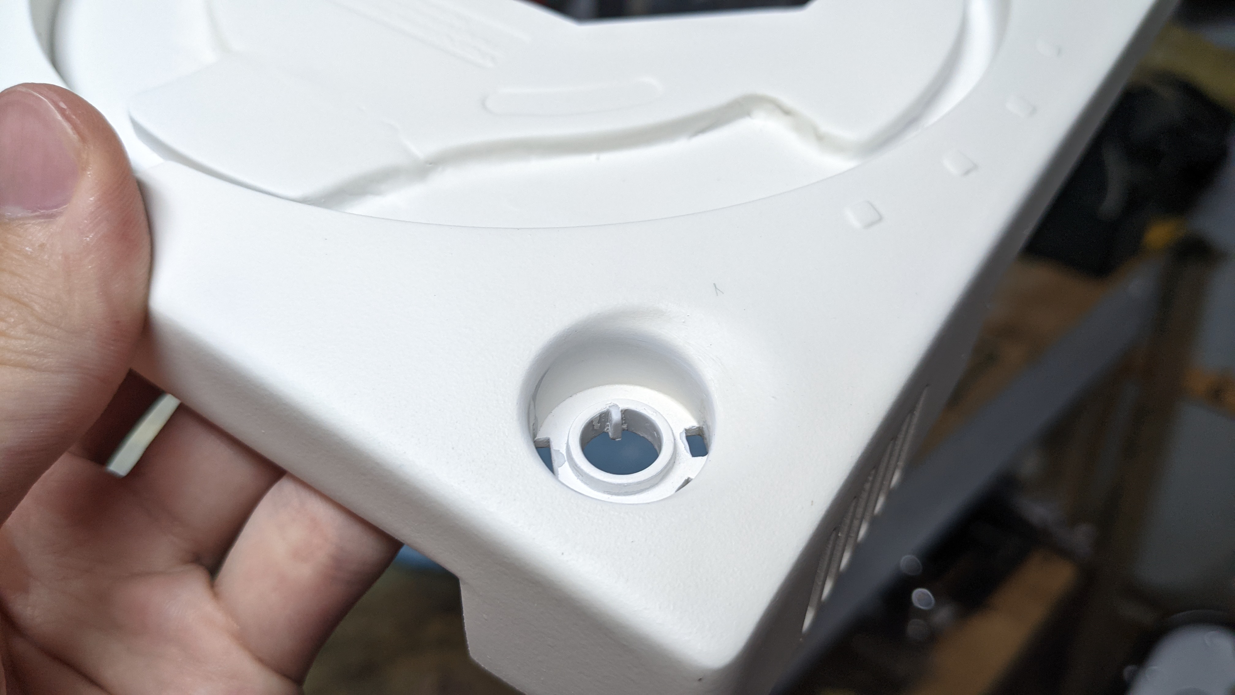
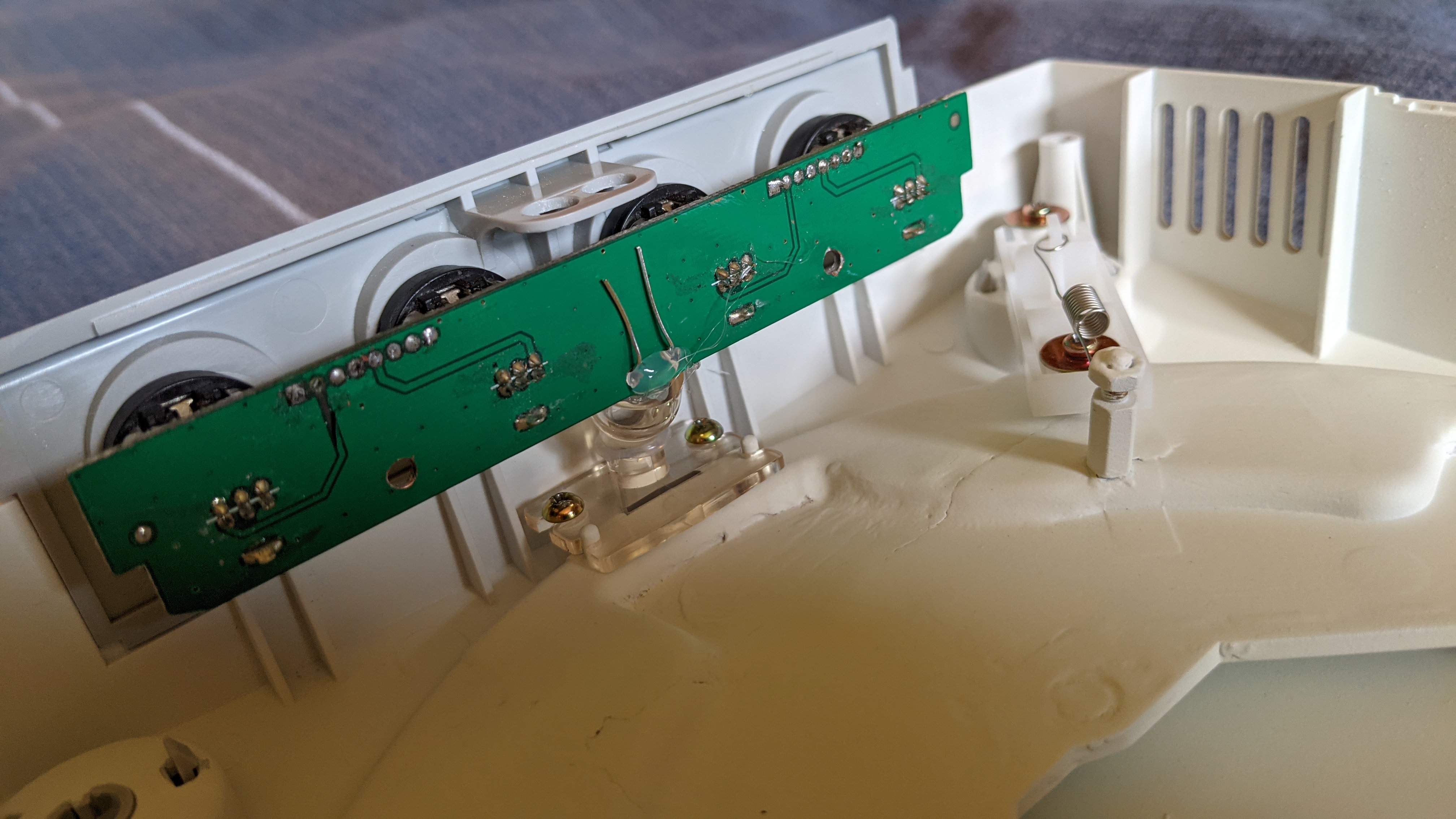
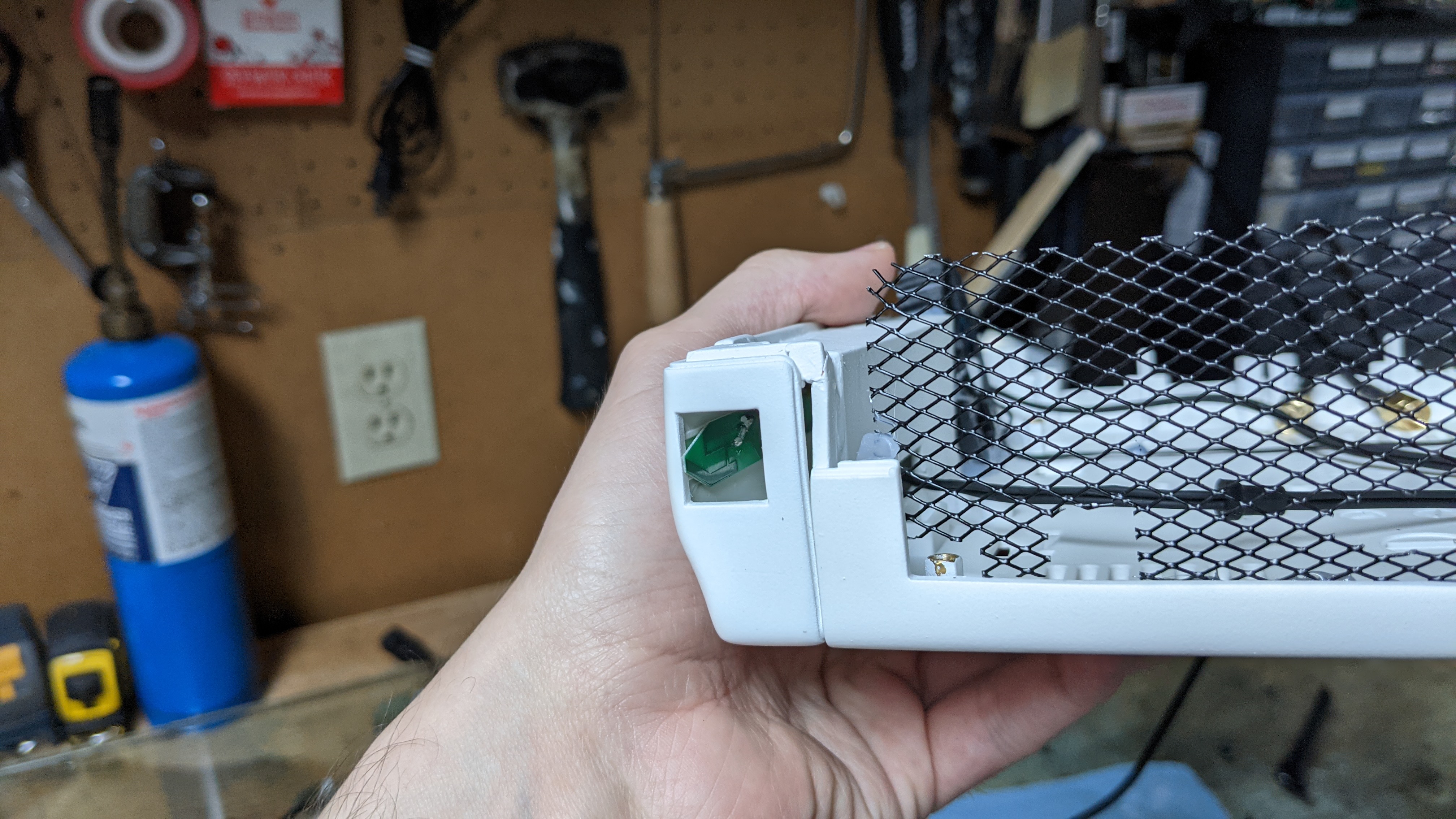
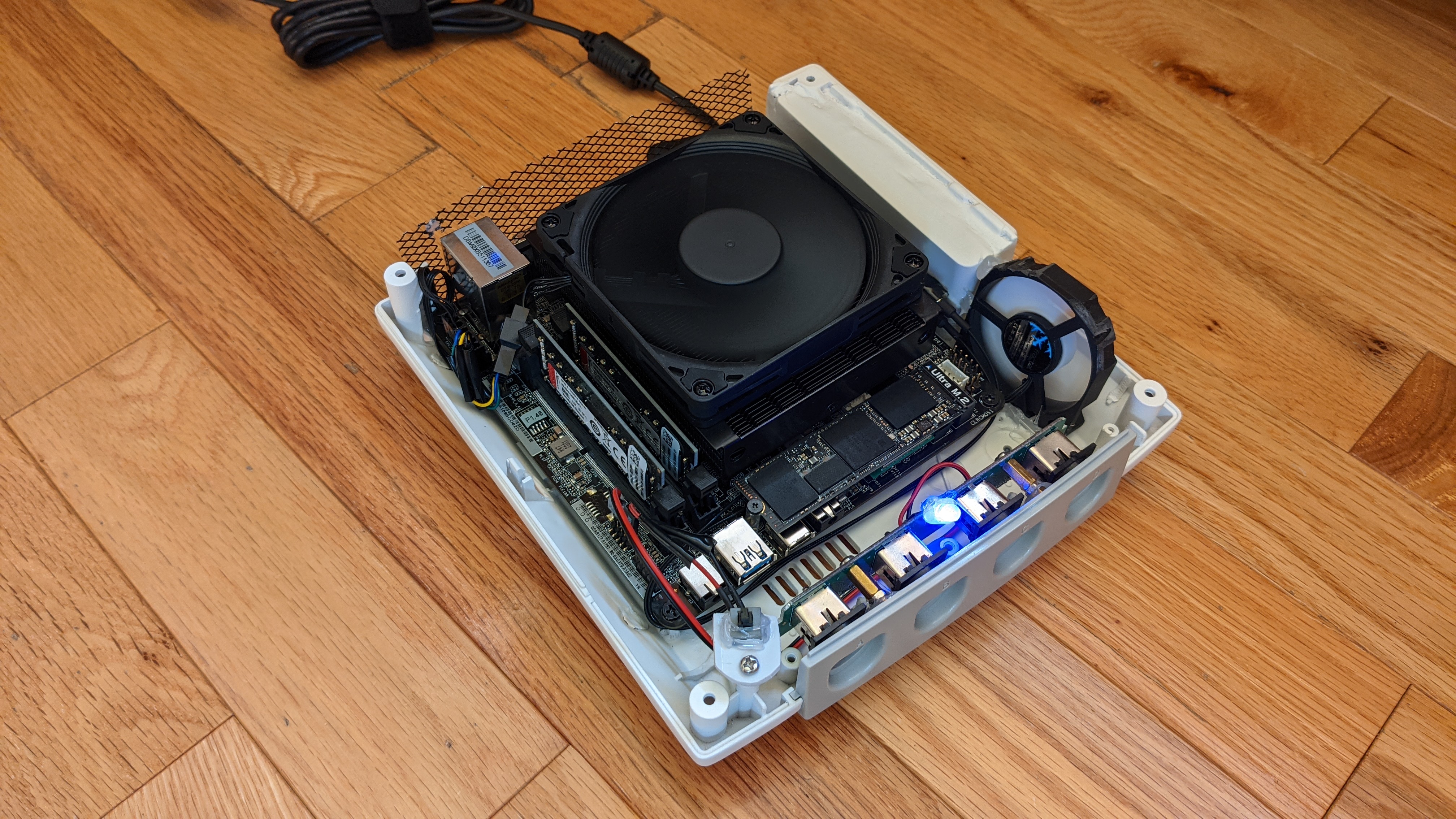
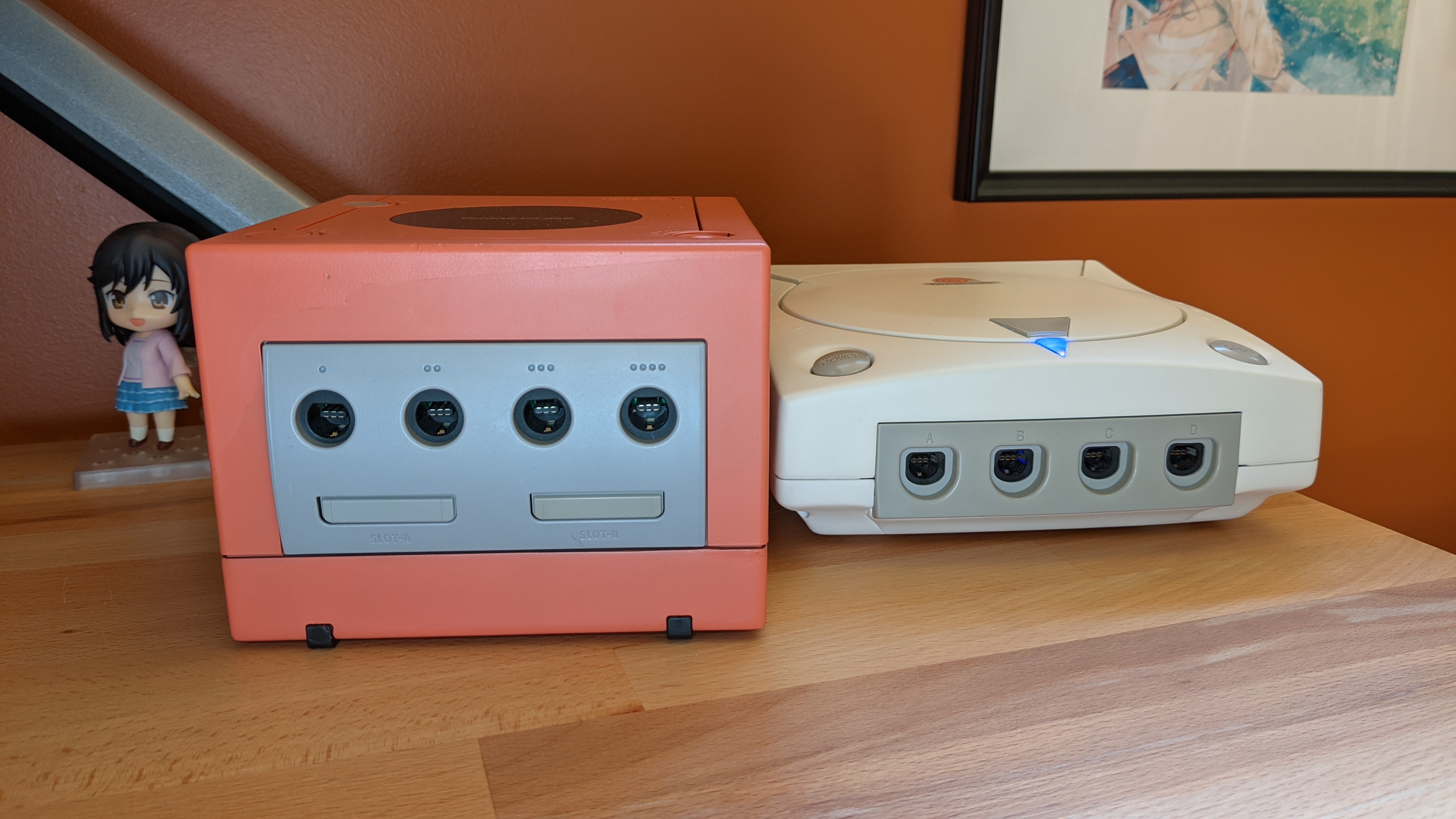
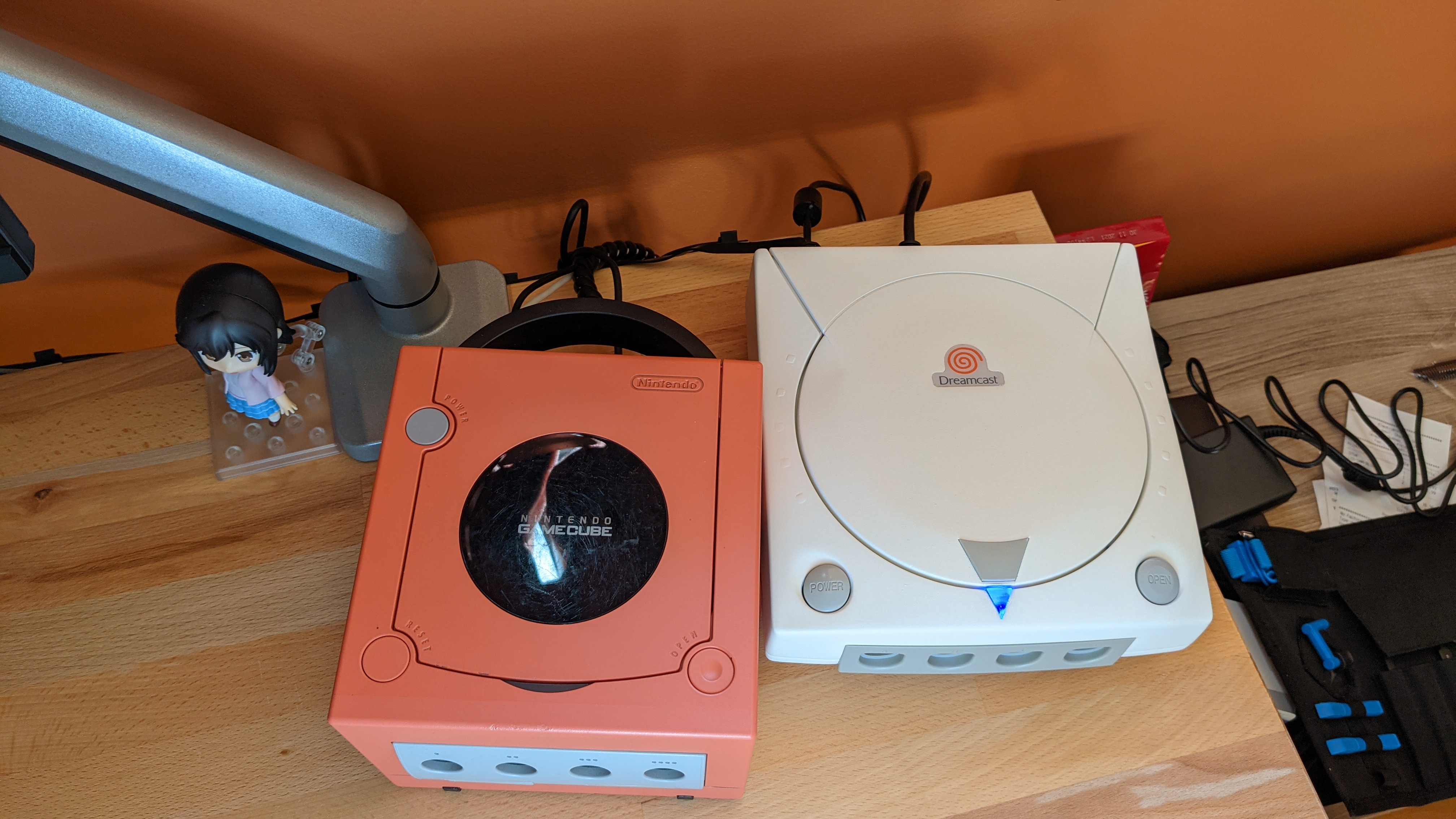
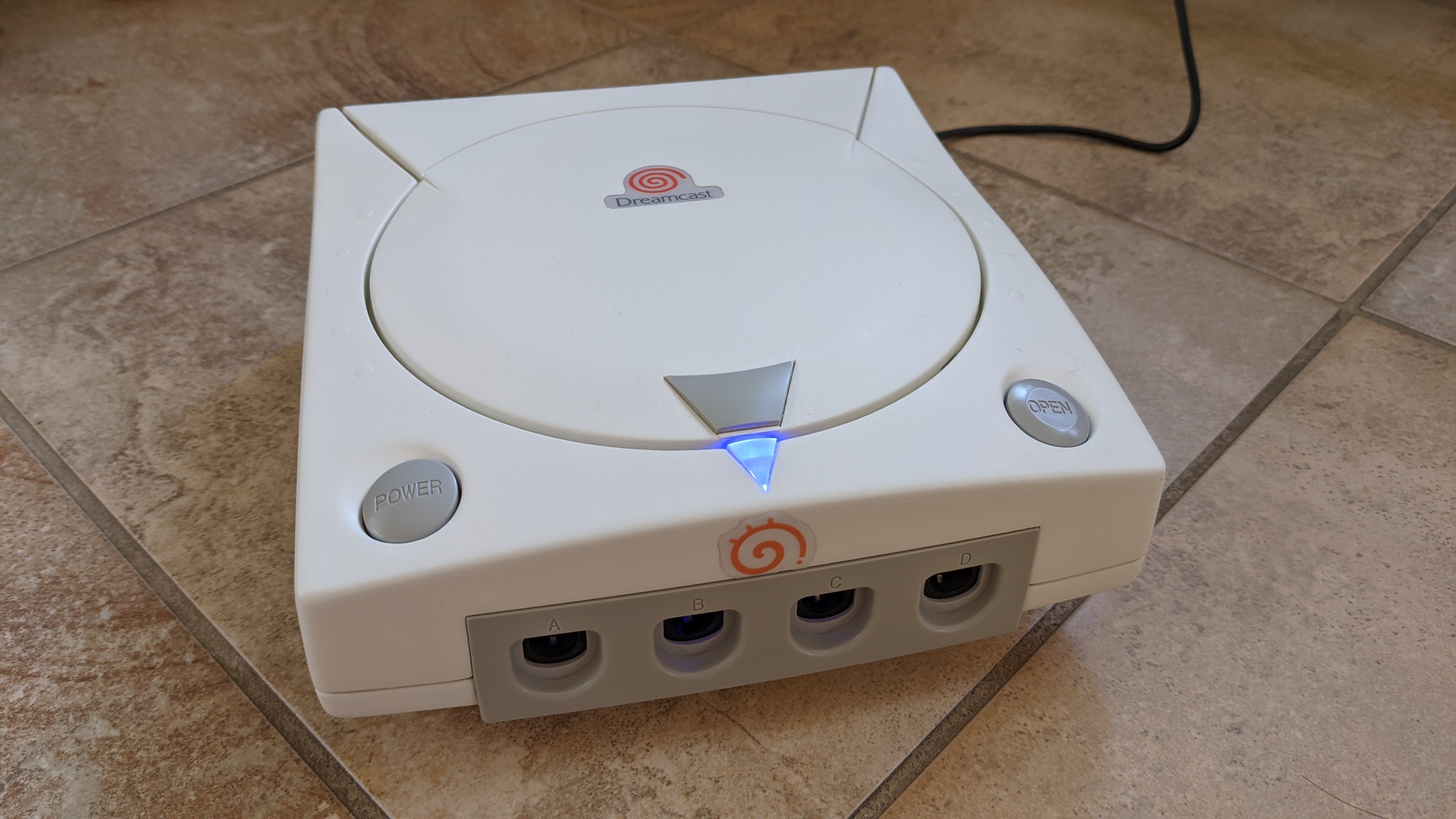
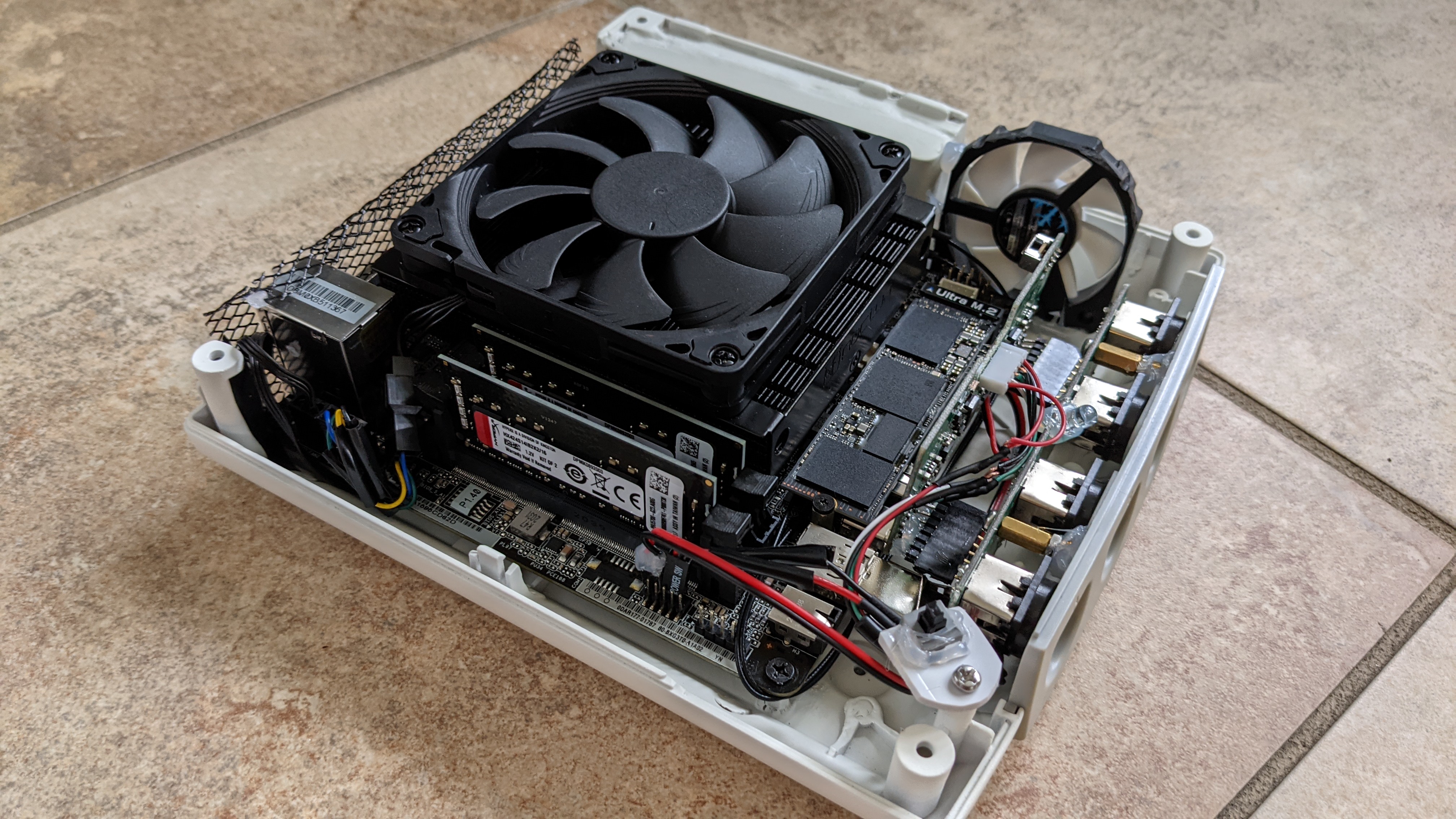
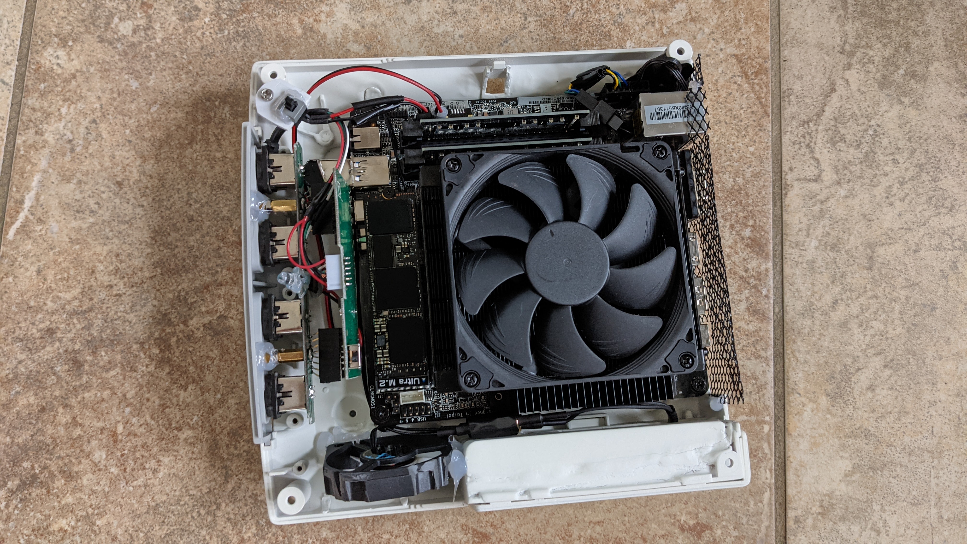
It would be so tidy and professional looking. ^^ I still need to look how I could optimize and reduce the size of the PCB. And if I put inside my current Gamecube, it would require some additional chopping off of plastic so it can fits. So that’s what boredom is trowing me into right now. Beginning to think about it, but might be a while before I put it into execution.

6 Likes

Dumb question but could you not simply do the 230W, do a voltage split with two resistors, then parallell buck instead of two step Buck?

I only know enough EE to be dangerous here. :slightly_smiling_face:

1 Like

Maybe, I don’t know, but space for two buck converter would still be a challenge. Plus at least with two cables, I can only power the PN50 and run off the integrated GPU if needed.

Same here :sweat_smile:

1 Like

19V will be a pain since that is such a non-standard voltage.
Then again, when you go custom-PCB, creating your own DC-DC setup is not a big step anymore.

I had good luck with Traco Power products for projects that needed small (<5W) DC-DC conversion, they make bigger units too. Just to open up your options.

Makes us 3, then again, my last fire was two years ago.

2 Likes

I just started the build log but I wanted to inform anyone frustrated with yellowing of these systems that there are chemical methods to reverse it.

Look up Retrobright. IIRC that should give you a recipe that you can use to make a paste that you’d slather on the chassis and then leave it out in the sun. After a while of “baking” the case will return to it’s original color.

EDIT: I see now that it was eventually mentioned.

Now that I’m caught up, I definitely think it’s a good idea to look into making a custom PCB for splitting a standard input into 19V for the MB and 12V for the GPU. I think you should also consider trying to find the circuit and parts for making a GxR-DIY yourself so that you can customize it for your needs more.

I think I’d try out a couple different designs for the board.

  1. A single board that is as tight as possible with all the features combined and no add-on boards. - requires the GxR-DIY schematic)
  2. A single board with separate add-on boards to get all the features - likely larger but saves on making them yourself
  3. A bunch of tiny boards the can wired together - Takes up the most space but you could spread them out throughout the volume of the build instead of clustering them

Also you mentioned issues with the power input for the GPU being blocked off at one point before switching to something else. I wanted to suggest being willing to desolder connections like that and wire them directly.

2 Likes

I wonder if J-Hack would be interested in a USB-C 48V@5A → 19V@5A + 12V@8A converter. IIRC a 5A PSU does not provide 5A, it provides up to 5A, and he has done similar Crazy Stuff ™ before… Of course, not very cheap, but he has done similar stuff with PicoATX stuff, so won’t hurt to ask? I recommend their discord. :slight_smile:

1 Like

Thanks, keeping it in my back pocket

It would be a good idea, but I think going that route will go waaaay above my skills. So option 2 is what I’m considering. Too much chance too screw up with option 1, and 3 is not tidy enough :grin: (but I could do that will see if I find change my mind…)

Oh ya that was when I was tinkering with the 1660ti, and didn’t want to risk soldering. Also, the length of the card was a little problematic, and I would need to conceive a custom heatsink to be able to support a 120W TDP GPU inside the Gamecube. (maybe in a v2)

Ya I know J-Hack stuff, and it would be an option, but I think I would be going toward the two cables approach. Less expensive at the end, don’t have to wait for PD rev3, more versatile, and no need to risk soldering the motherboard.

As a matter of fact, yesterday I decided to work on two designs of the GPU power delivery thingy depending of where I go with the idea, a 100W design and a 75W design.

100W, 95.3mm x 35.3mm using Pololu 12V, 15A Step-Down Voltage Regulator


75 W, 74.7mm x 24.5mm using Pololu 12V, 4.5A Step-Down Voltage Regulator
(I would need an heatsink on the converter with this one as I would go a little bit over the rated spec of 12V 6A (72W))

But with the announcement of the RTX 3050 with a TDP of 130W instead of 90W as I was hoping to (it’s higher than the 1660ti at 120W!) I think I will just go for the 75W design and stick with pin-less GPUs for which I only need to power the PCI-e adapter, like maybe the future Intel GPUs :thinking: 
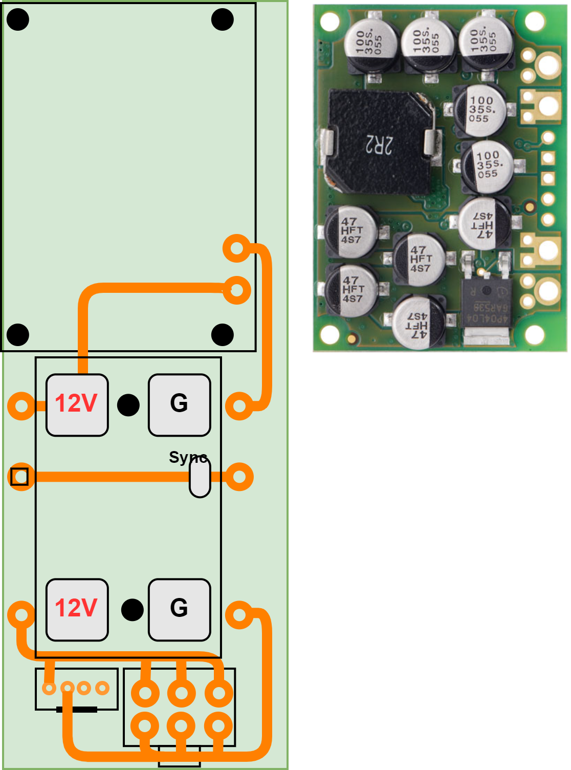
With the 75W option I would be able to easily put it right away in my build and use it.

2 Likes

Option 1 is definitely hard. The GxR-DIY looks like it might be a single sided PCB and if that’s the case it should actually be really easy to duplicate and you can probably find DC-DC converter schematics online you could use.

Definitely agree with Option 3 being messy though. However, it could buy you a good chunk of space compared to a bigger single module.

That’s reasonable, if you aren’t confident then you don’t have to.

On the heatsink, what are your thoughts on an extremely tiny water cooling loop? That’d shrink the GPU quite a bit and might save some height on the CPU so you can get them tighter.

Another crazy idea might be to use the Gamecube accessories to give yourself additional room to work in. You could use the Gamecube screen and the Gamecube Gameboy Player to give yourself some more space.

1 Like

Seems yo be even more complicated, plus when I’m speaking of lenght, U’m speaking about the lenght of the PCB itself.

No I don’t want to butcher the Gamecube. I want to keep the spirit of the Gamecube. I will clear up more floor space in a v2, but not further that. I know someone on smallformfactor.net did that, and I don’t like that at all. Plus it’s the fun of the challenge to work with important constraints.

1 Like

What’s your definition of butchering and the reasoning behind it?

1 Like

Did another design of the 100W version. Will definitely go with a 100W design to as this design stay within the spec of the step-down regulator.

1 Like

This topic was automatically closed 273 days after the last reply. New replies are no longer allowed.