[Build log] Re;Gamecube PC

Well… today was eventful…

But first from the beginning.
Did a compact splitter for the fans. Happy with result.


And then I proceeded to build up the Gamecube to see if I would be able to build it completely or if some modifications was too be required.

So first mounted the SSD and wifi antenna inside, making sure the wires are tuck away


Then I installed the back IO with the 19V to 12V converter. Was a bit challenging as the wires are kind of too short, so they were under tension. Made it difficult to screw down the converter board. Would require to lengthen the cable.


Neat thing I did was to put a paper golden ring for the GPU power, with the corresponding power brick, to ensure the right one was connected.


After came the time to put the mobo and to connect the sync cable, and the wifi antennas. Not beofre mving the small heatsink on the converter first as it entered in conflict with the CMOS battery connetor.


Then came the installation of the nvme to pcie adapter

And the front panel. I ended up putting a lot of things on it. Thus you have the fan controller, the reset button (for tactile purposes only) and the LED (with the connector for the MOBO and a connector for the power button) that are glued to it.


Then come the installation of the left button (and I noticed I forgot to plug the Gamecube adapter too before)


And of the right fan. I installed a connector for the power button so that piece can easily manipulated without being tethered to the front plate.


But then I realized I should try to put the GPU first, and trying to install the acrylic floor and GPU revealed several part that needed further cutting to make everything fit.


At least I tried to power everything on. But nothing. After several troubleshooting steps, I first discover that I inverted the polarity on the sync cable. I used the same order than when I switch up the colour of the wires in my 3D printed build.


And also there was the power button and led that were not wired up right, but I stopped after having the right order for the power button, with only the LED left to deal with.

But then the event happened

I was fed up from today. So I stopped working on it letting everything sit as is, and I went to quickly grab something at the pharmacy. And when I came back at the house there was the smell of magic smoke. Luckily my brother was there and knew right away to just disconnect the power cables of the build. And trying to find the culprit, I ended up with connector for the GPU power that was molten.


I don’t quite explain why that happened. I thing it’s maybe because I melted a bit the plastic between the positive and negative terminal last time I soldered? And also it was a bad idea of mine to rely on hot glue to isolate the soldering job…

But the mobo is alive, and most surprisingly the GPU is still alive, it worked on my ITX mobo. I don’t know if the converter is still alive, and I don’t want to try. But it did well it’s job, it protected the GPU from the meltdown.

So I don’t know what to do now.

I still have the GxR-DIY and the 12V power brick, so I could power the whole build as I did originally. Or I could just ditched the GPU and be only with the PN50. Like technically the PN50 alone would still be a capable machine for emulation for a potential buyer. But I’m losing a lot of the potential value of the build.

I will think about it, but now I will maybe take a break from the project, because my god always so many little things to worry about with those kind of builds.
And maybe I will build first my other case, as I’m getting annoyed to have my new mobo and hdplex lying on my desk open-benched style

But now my bedroom still smell like magic smoke :upside_down_face:

7 Likes

Wow! I’m glad your brother caught it in time before your whole place went up in flames. I know that both switches and pin sockets are a PITA to solder correctly.

Because there’s plastic that holds the contacts in place, you have to either solder to the pins extremely quickly with high heat, or try to “sink” heat away from the housing. Usually this is done either by holding tweezers/pliers on the pin (if it’s long enough), or by having something plugged into the socket while soldering it.

BTW, I noticed in your shot of the 19V to 12V buck regulator, that the heatsink was placed on the choke/inductor. Those don’t need cooling. Ideally it should be placed on either the external MOSFETs, or the controller chip if it has integrated MOSFETs.

I’ve been following your tiny builds the past couple years, and I’m quite excited to see how this one turns out after you return to it. :smiley:

EDIT: If all else fails, and there’s not enough space to place a heatsink on the voltage converter, you can probably actively cool it with a nearby fan in the case.

3 Likes

Ya fortunattely.

I know such a pita to solder. I know I added too much heat to my liking when I soldered it, however when I used the multimeter, everything still seemed fine, with no apparent contact between the positive and negative ends. But ya defintely melted some plastic. I should get a better soldering iron :sweat_smile:

Oups :no_mouth: I was sure it was the heat generating component :sweat_smile: Thanks for the head-up. But at least the converter was still sitting right bellow the fan, so the compoents would still have gotten at least plenty airflow lol.

Thanks :smiling_face: But ya thinking I will switch to the 12V route, will see.

3 Likes

So I did some work lately on the build. I decided to continue with the 19V route, as the converter is still functioning, without any damage. I’m just using a different connector so now this time around there is absolutely no risk of a new meltdown lol. Tested everything and everything works as usual.


The new connector fits very snuggly between the standoff and the CPU cooler. Now I need to spray paint the back IO again.


And now I’ve been doing a lot of small adjustment to make sure everything fits inside. It seems that every time I adjust something, it just get even more tight inside with new collision points arising. So a lot of minute adjustments that I hoe I will finish this weekend.


5 Likes

So close to the goal… but still need to wait for another thing.

The pieces that needed painting were painted and I waited almost 5 days for them to dry really well


And then I proceed to solder again the GPU power connector. This time also I soldered at a 90 degree angle so the cables are more easily manageable.


And then was time to reassemble everything back together. It’s so tight it’s not even funny.


I cut a small of acrylic to act as a lock for the GPU. Finally I just installed the rear one, because no need to have one in the front.

I still needed to do some adjustments because the power switch was not well aligned with the button.


And everything was working! Until I got an issue with the 19 to 12v converter. So I bought a new one and I need it to get to me. While allow to start from from a blank state and solder everything properly the first time, to it’s the cleanest and safest for any buyer.

Oh and I decided to back the shell on the Noctua fan controller
because I always forget which way I had to plug the cables.

5 Likes

I received the new converter yesterday, so I proceeded to solder everything down. Took some time because at one time I soldered a part in the wrong hole despite having checked twice, but I did as clean as soldering job as I could do.


And at last everything fits and works! Everything is solid.


I just forgot that at some point I changed the wifi card for a Mediatek 6e one. Driver support with Windows is shitty lol. I had to manually add the driver with device manager. Last time I did that was in Windows 7.

However, I was finding the temps on the CPU high, like in the 70sC when doing basic stuff. I arrived at the conclusion it was because of my fan setup that choking the CPU cooler off for air. I had one for intake, one for exhaus, thinking it would help reduce temps. In that case, I really need to have as much positive pressure I can to feed air to the CPU to bring down temps in the 50sC.


Conducted Time Spy, and the performance result is the same as usual, no meaningful difference with the previous 3D build, so that’s good.


And I tried the new Steel Nomad (light) test for small systems (I have an error when lauching the normal one). Apparently I have great performance for a laptop hahahaha


I will continue to stress test it before putting it for sale, but at least it’s working! The build is finished!

5 Likes

So I did a lot of tests yesterday, and this morning. At first I was finding the PC chuggy, but then properly updating AMD and Nvidia drivers swiftly solved the problem.

I did also an extended SMART test t make sure the SSD was all right, which it is.

I stress tested with FurMark and Prime 95.


While stress testing, and gaming, I noticed the Gamecube would get so heat soaked. So I decided to put back one of the fan as an exhaust, and I did a small funnel to redirect the intake fan’s air toward the converter and the CPU fan. And that helped a lot. The CPU when gaming do sometime spike at 99C, but it doesn’t affect performance much.


Here’s a test of all the noises of the Gamecube, when starting, under beginning stress test, and when closing

I did so many recording for either them for not work, or me forgetting to save them, so sorry for how lackluster they are. I was able to fully screen record with the Gamecube emulation, but when trying CS 2 and GTA V, I would get after about 5-7 minutes frame dropped because it was too taxing on the GPU. So i recorder the Game with the Windows built-in game recorder.

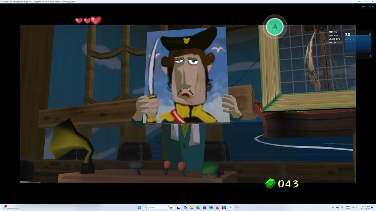
Gamecube emulation, 1440p, no anti-alliasing, no FSSA (Wind Waker constant 30 FPS, Mario Kart constant 60 FPS)

CS 2, 1440p, high settings, average 60 FPS

(Old) GTA V, 1080p, high settings, average 50 FPS
(I just noticed GTA V refresh rate was setted at 50 Hertz, that explain why that time it was at 50 when a previous time I was able to get 60 :skull:, will add a new recording soon)

(New) GTA V, 1080p, high settings, capped 60 FPS

So I will do the glamour shot and put it for sale later today. Do you think that $740 US is reasonable as a price to sell it?

5 Likes

And here are the glamshots


5 Likes

Good to know that my Gamecube PC isn’t the only one which is a tad noisy. The problem with the plastic grid is that it creates a high pitched whine with high RPM fans (the cube wasn’t really designed for high airflow / pressure). At least with some “low noise” adapters I got the fans down from a very annoying “weeeee” to a very faint “driver died on the wheel with face on horn” sound.

2 Likes

Oh ya it’s difficult to not be noisy with those. But supprisingly this time around, my side fans are not that noisy, and they run at max speed. I think this time they are fuether from the Gamecube shell, so there is less turbulence.

But ya enclosing them do being theie noise, along with enclosed GPU and CPU fan

If you can spare the airflow, fan filters can also help a lot with noise.

The GameCube I got had some mesh filter preinstalled, I think later GC models came with it - or it was even third party. Unfortunately I had to remove it because the case fans sit snug against the case without any wiggle room. (I used a modding kit with premade 3D printed parts.)

1 Like

Ya, too tight too even fit a fan filter hahaha. I have the Gamecube fan filter too, but I would not be able to slide down the shell with it.

1 Like

This topic was automatically closed 273 days after the last reply. New replies are no longer allowed.