@droptheghost If I were to run the default frequencies then yes, I would be getting regular single-bit errors and potentially get some uncorrectable 2-bit errors in the future - which could be dangerous.
But I am running non-default settings:
I currently have 2 dual-rank 2666Mhz 16GB sticks which by default go down to 2400 (on ryzen 2600). After going to the OC menu and setting 2666 I get no more ECC errors. After extensive testing I do not believe I will be getting any error rates that would be out of expectation, so I would consider my data safe.
Also: Even on the default 2400Mhz: If I disable ECC in the BIOS I would expect those corrected errors to become real bit-flips. But it does not happen - I get no errors. So my interpretation is that those errors are a subtle memory training/timing issue which fixes itself with just a small nudge.
** AFAIK this only applies to the one board I have and others are probably fine.
Hi everyone,
I am a new owner of a X470D4U, and for now I am quite satisfied with it.
I am using it as a home server/NAS, with a PCIe 10gbit and PCIe LSI passed thorugh a freenas VM, and a SSD as a boot/VM storage disk.
I decided to add a few extra disk (directly connected to the SATA on the mobo), which are correctly recognized, and then 2 m.2 NVMe (Sabrent M.2 PCIe Gen3 x4.) to be used as extra (and fast) VM storage which I can’t manage to have the system recognize.
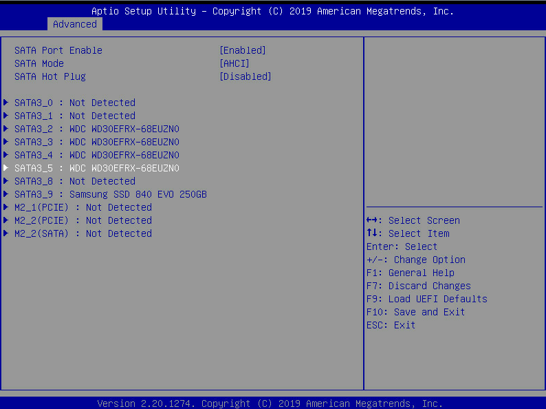
I can’t see them in the BIOS, or in the hardware list in the IPMI interface.
Is there something I need to set in the BIOS? It seems really strange that both NVMe could be defective…
Just to clarify: When you say that you ‘do not see them in the BIOS’ do you mean the ‘Advanced > Storage configuration’ page?
There are a few things that you could check:
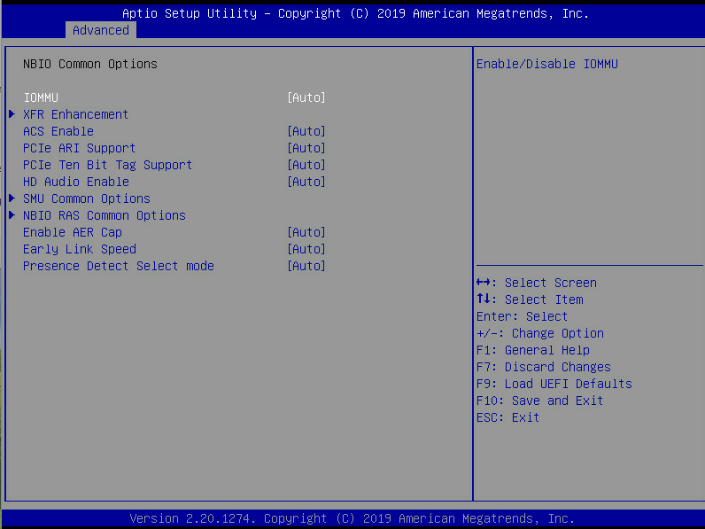
Are you using ‘advanced>CBS>NBIO>Force PCIe gen speed’? Or NVMe raid next to it?
Did you try CMOS reset?
What BIOS version are you using? (3.20 advertises better M.2 support)
Maybe try to disconnect the SATA and USB3 devices (This should not matter)
What CPU are you using? (Maybe some APUs or 1st gen Ryzen cannot handle some configurations?)
If you have any NVMe drives from more ‘mainstream’ producer then try them (Intel, Toshiba, Samsung, Micron, Seagate)
Some boards disable M.2 slots when using PCIe slots but this should not happen on this boad. Using any PCIe slots should not make any difference since both M.2 slots are not sharing any lanes with them. (to make sure I confirmed this by populating all PCIe slots and still getting a working NVMe)
Also:
2 m.2 NVMe (Sabrent M.2 PCIe Gen3 x4.) to be used as extra (and fast) VM storage
If you expected to get full bandwidth out of them through the on-board m.2 connectors then think again. Both M.2 slots are connected through the chipset and will run at PCIe x4 gen2 for the M2_1 slot and PCIe x2 gen3 for M2_2 slot.
You may consider a ‘PCIe to M.2’ card in the PCIE5 slot (the x8 physical one in the middle) It is connected to the CPU and should run at PCIe gen3 x4 speeds.
Yeah, I guess that the NVMe options will not be present if NVMe drive is not detected…
You can find it the manual. The procedure is as follows:
Disconnect the power, remove the battery and short 2 contact pads next to the SATA 8/9 slots and PANEL1 connector (It is marked as CLRCMOS1 on the PCB)
Thanks. I just made the reset, but nothing changed (the date inside the bios was reset, so I am fairly sure that I did it correctly).
I will try taking out one of the NVMes and test each port one at a time.
Should everything else fail, do you have any suggestion for a PCIe-2-m.2 card to insert in slot 5 (the middle, x4 one)? On amazon I saw a few of them but they’re… suspiciously low cost (10-20€ range). In particular is there a card with two m.2 slots so that I can use both of them?
Concerning the NVMe you managed to get working with the board: can you let me know the brand/model?
As a quick update: tested the slots one at a time and still zero success
I will try the NVMe in my desktop PC later, but in any case I am pretty sure that it is impossible that both of them are broken.
Should everything else fail, do you have any suggestion for a PCIe-2-m.2 card to insert in slot 5 (the middle, x4 one)?
What I said about the PCIe>M.2 card concerned bandwidth only. Without knowing what is causing your incompatibility I cannot guarantee you that such card will make it work.
About the bandwidth:
Before deciding to buy into PCIe gen3 x4 ask if you even need it.
Check what your drive can actually do and compare to the limits below:
From https://en.wikipedia.org/wiki/PCI_Express :
PCIe gen2 X4 can theoretically do ~2000 MB/s
PCIe gen3 X2 can theoretically do ~1970 MB/s
Those are each way. So if your drive can do 3GB/s sequential read then you will not get it. But you mentioned that the primary use-case will be VMs so I guess it’s more of a random R/W. In that case you will be most likely more than fine.
Just keep this in mind when you decide do something more ‘sequential’ in nature.
On amazon I saw a few of them but they’re… suspiciously low cost (10-20€ range).
NVMe M.2 ssds are using PCIe. The connector is just different so those adapters are really simple - This means low price. The thing to look out for is stated PCIe gen support.
In particular is there a card with two m.2 slots so that I can use both of them?
You could, but those cards slots require bifurcation to function. X470D4U supports 4x4 but AFAIK you would lose the bottom-most PCIe slot.
With 4x4 bifurcation enabled top-most slot would be split into 4 x4 groups and bottom-most slot would be disabled.
At this point you could use one of those adapters. (1, 2, or 4 M.2-slot ones should work)
Engagement challenge: Is it possible that this board supports 4x4 bifurcation across 2 slots (2 x8 slots bifurcated into 2x4 each)? Or maybe some of you seen something like this on other boards? Theoretically it should be possible especially since 2x8 is supported. So it would be just splitting both of those x8 in half.
Concerning the NVMe you managed to get working with the board: can you let me know the brand/model?
I am using Intel 760p series
As a quick update: tested the slots one at a time and still zero success
I will try the NVMe in my desktop PC later, but in any case I am pretty sure that it is impossible that both of them are broken.
Yeah, smells like some incompatibility, I sent you a 3.33 BIOS I got from Asrock support to test.
You could also check if you have any SSD firmware updates available on Sabrent website.
Update: I tested the two NVMe on my desktop PC… and even there they are not recognized (the two M2 slot I used are PCI3x4, so I guess it is not possible to get a better matching than that). At this point I am guessing that it was just bad luck and I ended up getting both from a bad batch (as improbable as this is). I am sending them back to Amazon.
I’ll look for an intel 760p and see how it goes. Unfortunately I am using 2 PCIe at the moment (a 10gbit and an LSI), so I can’t afford losing one.
You may also try contacting Sabrent support.
And if you aren’t in a hurry than wait a while for other responses here - someone may have other suggestions.
I tested the two NVMe on my desktop PC… and even there they are not recognized
Is your desktop also Ryzen based? If yes then please check for the SSD firmware updates.
The beta bios 3.33 has been super flakey for me. I’m getting pretty consistent crashes. Centos was running flawlessly. I only upgraded to fix the pci header 127 error. I’m going to have to go back to 3.30.
Did anyone manage to get ESXI working on X470D4U2-2T?
I keep getting stuck on “Initializing storage stack” when CSM is enabled or no drives detected when disabled.
BMC is on version 1.7 and bios 3.31.
specs:
2 X 2TB HP NVME drives
AMD Ryzen 9 3950X
128 GB DDR4
I can’t say anything about ESXI specifically but I did struggle with missing storage devices and CSM weirdness - I had for example a problem with USB install sticks not being recognized by the BIOS no matter the Boot options. (OS saw all devices without issues)
The issue was with VMedia that IPMI provides.
O had to go to the IPMI web interface> ‘Settings’ > ‘Media Redirection Settings’ > ‘VMedia Instance Settings’ and set all the device instances to zero. Only then my USB stick would become visible (and bootable).
You also may want to fiddle with the IPMI settings.
@Tenrag Thank you for that. I just got mine together tonight and at first it saw my USB and then it was giving me all of these virtual drives. I probably wouldn’t have figured that out tonight without your comment.
Depends on the version of ESXi you’re trying to load. At some point the NVMe driver got updated and the requirements to be recognized as a datastore got more stringent. Here’s an article stating some things about it. Recommend trying ESXi 6.5 instead of 6.7U1 or above
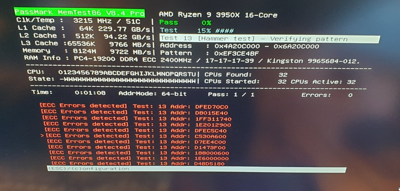
Although I’m very happy to hear that he managed to see reporting of ECC Errors on the Asrock Rack X470D4U when using a Ryzen 3950 (Zen 2), I’m also confused and puzzled to what this means for my failing experiences to achieve the same…
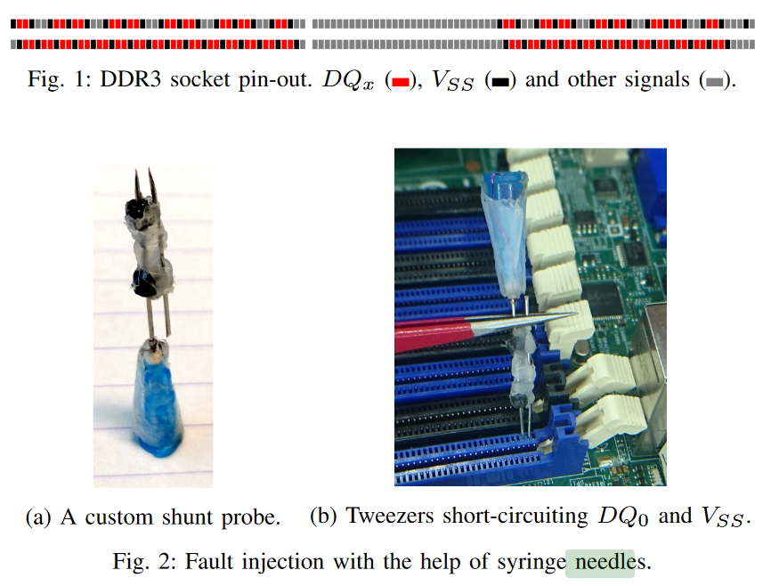
Causing memory errors by shorting pins of memory modules
Firstly I did some research on this “Triggering memory errors using ‘needles’ or wires”-approach, which Diversity has used. I didn’t look into this method yet, as it seemed too risky and I didn’t want to damage or degrade any of my hardware.
So in short, you’re connecting a data-pin with a ground-pin, so that the current on the data-pin “flows away” into the ground-pin and this “flips a bit”. When using the correct pins and not accidently shorting anything wrong, this should actually be “reasonably safe” to do I think… (please correct me if I’m wrong )
Why is this causing single-bit errors and not multi-bit errors? I THINK because every “clock tick” data is pulled from each data-pin of the memory module. So if you change only the “result” of 1 pin, you get a maximum 1 bit flipped per “clock tick”, which ECC can then correct. (not sure though)
This paper is already a bit older and was using DDR3. The ‘AMD-1’ configuration they are talking about (where interleaving is making things complicated) is an ‘AMD Opteron 6376 (Bulldozer (15h))’.
As far as I understand, the extra complexity of “interleaving”, that happens on the Opteron system, is only applicable on Ryzen, when using Dual Rank memory. As Diversity was using a single 8GB module, I suppose he only has single rank memory, so wasn’t confronted with the “interleaving-complexity”. However, if I would try this with my 16GB modules, I would be confronted with this extra complexity, because ?all? 16GB modules are dual rank…
I concluded this from this article (but I could misinterpreting things!):
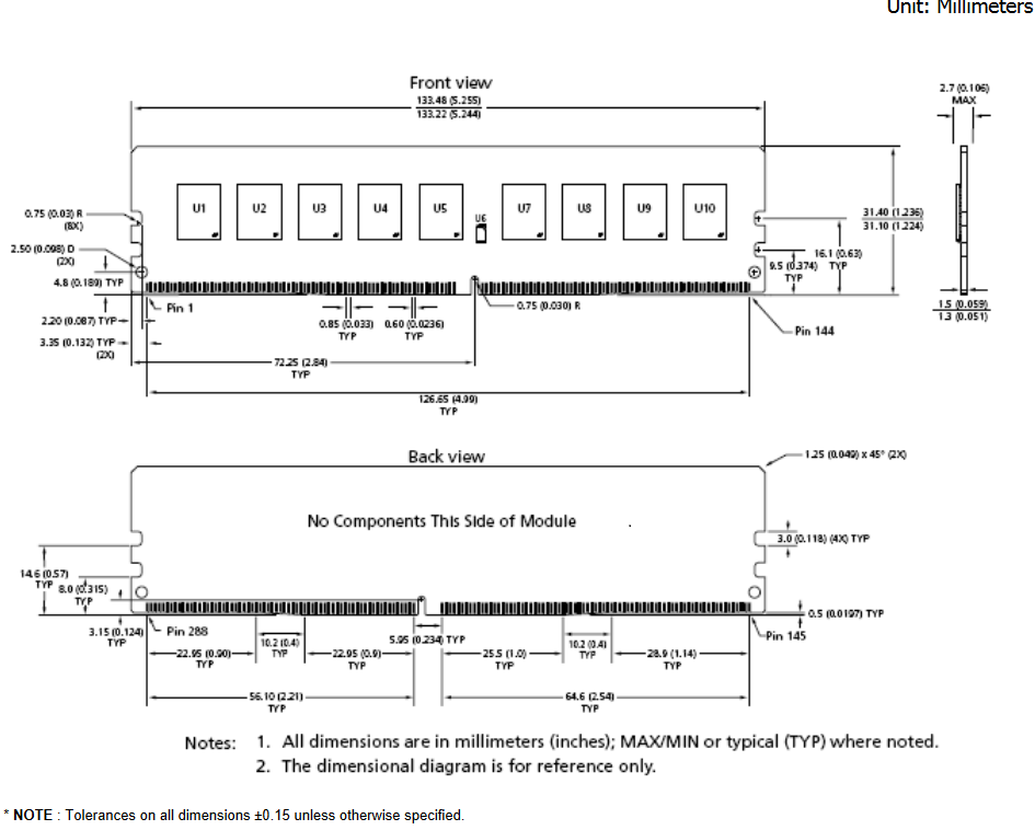
As the paper was for DDR3, you of course need find the pin layout of DDR4, before you can apply it on Ryzen. Following datasheet has pretty clear pin layout of unregistered ECC DDR4 module:
On page 6, 7 and 8 you can see the description per pin and on page 17 you can see a picture of where those pin numbers are on the memory module. I suppose all VSS-pins are ground pins and DQ+number pins are data pins. So if we follow the example of the paper and short DQ0 with a VSS, the corresponds to shorting pin-4 (VSS) with pin-5 (DQ0). But I guess shorting pin-2 (VSS) with pin-3 (DQ4) could work equally fine.
This should help us “understand” a bit better what Diversity has done and how to “safely” reproduce it.
The results from Diversity
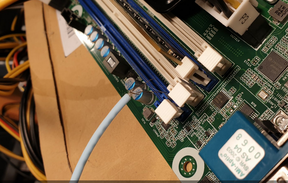
I was in contact with Diversity and have some more details on his testing (all pictures in this “chapter” are from Diversity himself). Diversity used the following video: https://www.youtube.com/watch?v=_npcmCxH2Ig. Instead of needles and tweezers, he used a thin wire, as in the picture below.
As you know, I also tried triggering reporting of corrected memory errors. I tried this by overclocking / undervolting the memory to the point where it is on the edge of stability. This edge is very “thin”, can be hard to reach and can result in the following scenarios in my understanding:
Not unstable enough, so no errors at all
Only just unstable enough, so that single-bit error occurs only sometimes when stressing the memory enough. These will then be corrected by ECC and will not cause faults or crashes.
A little more unstable, so that single-bit errors occur a bit more often and less stress is required on the memory to achieve this. But also (uncorrected) multi-bit errors can occur sometimes, which could cause faults / crashes.
Even a little bit more unstable, so that mostly multi-bit errors occur when stressing the memory and single bit errors might be rare. This also makes the system more prone to faults and crashes.
Even more unstable, so the multi-bit errors occur even when hardly stressing the memory at all. This makes the system very unstable and probably will not be able to boot into OS all the time.
Too unstable, so that it doesn’t boot at all.
Both scenario 2) and 3) are “good enough” for testing reporting of corrected memory errors. Perhaps even scenario 4), if you’re lucky…
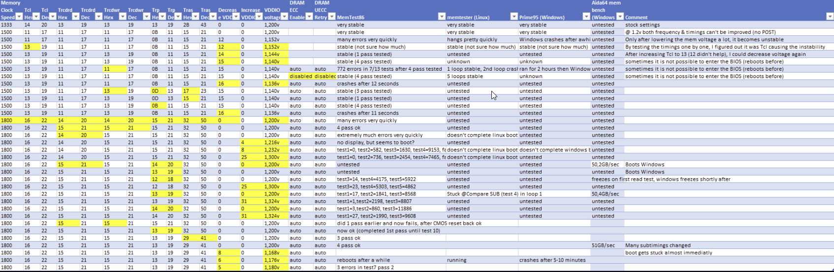
During all my testing I tried 100+ possible memory settings, using all kinds of frequencies, timings and voltages, of which 10-30 were potentially in scenario 2) or 3). I “PARTLY” kept track of all testing in the below (incomplete) Excel:
This convinced me that I should have at least once been in scenario 2) or 3), where I should have seen corrected errors (but didn’t). That is why I concluded that it didn’t work and I contacted Asrock Rack and AMD to work on this.
Conclusions / Questions / Concerns
Now what does all of this means? Does this mean that I never reached scenario 2) or 3)? Does it mean scenario 2) and 3) are almost impossible to reach using the methods I tried? Or does it mean that Diversity perhaps triggered a different kind of memory error? I’m not sure and I hope someone can clarify…
I know there is error correction and reporting happening on many layers in a modern computer. As far as I know, there are these:
Inside the memory modules itself (only when you have ECC modules). The memory module then has an extra chip on the module to store checksums. I think this works similar to RAID5 for HDDs. So that a memory error is detected and corrected in the module itself, even before it exits the memory module.
On the way from the memory module to the memory controller on the CPU (databus). Error detecting / correcting / reporting for these kinds of errors are handled by the memory controller in the CPU, so ECC memory isn’t even required to make this work.
Inside the CPU data is also transfered between L1/L2/L3 caches and the CPU. Also there Error detecting / correcting / reporting is possible I think.
All of these might look confusingly similar when reported to the OS, but I do think they are often reported in a slightly different manner. I’ve seen reports where the CPU cache (L1/L2/L3) was clearly mentioned when reporting a corrected error for example, but I’m not sure what the exact difference between reports of 1) and 2) would be.
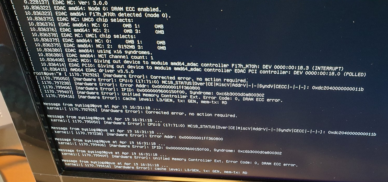
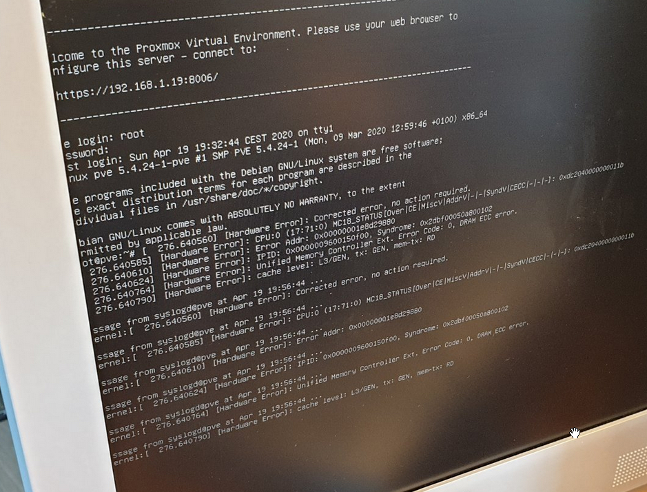
In Proxmox screenshots I do read things like “Unified Memory Controller…” and “Cache level: L3/GEN…”, but again, I’m not entirely sure if these mean that the errors are in 2) or 3) instead of 1)…
Diversity is draining the current from a data-pin “outside” of the memory module, but I still see 2 possibilities of what’s happening:
1) The drain on the data-pin is pulling the current away also inside the memory module itself, where the memory module detects the error, corrects and reports it.
2) The drain on the data-pin only happens after the memory module has done its checks and the error is only detected on the databus and corrected / reported there (so not by the ECC functionality of the memory module).
To know which scenario is happening, we could:
try to find someone with knowledge on exactly how each type of error is reported and who can exactly identify what is being reported
perhaps using a non-ECC single-rank module also reports the same kind of ECC errors, which would proof it is happening on the databus.
perhaps someone with more (I don’t have any actually) electrical engineering knowledge can also say something more meaningful than myself?
Diversity did mention that his IPMI log was still empty after getting those errors. So there the motherboard / IPMI is certainly missing some required functionality.
Edit:
As Tenrag correctly commented, the memory modules don’t do “on-module-error-detection-and-correction” because they’re missing components to do so. So even when using ECC memory, it is the memory controller on the CPU, using the extra parity chip on the memory modules, that detects / corrects / reports the memory errors.
Also according to Tenrag, the EDAC output does point to actual memory errors being detected (-> DRAM ECC error) and not data bus (infinity fabric) errors (-> link error).
Finally MasterPhi also correctly questioned if I had disabled PFEH during my testing and I did not actually, since I only discovered this BIOS setting very late in my testing (I only did my final testing with PFEH disabled).
So I may need to do some more testing with PFEH disabled…
I initially wanted to try out 3.33 for the agesa version that fixes pci pastthrough. I couldnt keep my machine up for more than 5mins.
I then tried to flash back 3.30 had instability where it was functioning perfectly for the past 3months. So at a last ditch i flashed 3.20 and it’s been running ok for the past 9 hrs. I’m running centos8/fedoraserver31.

 )
)