I have an LED strip that just has 5V and ground pins (2 each, but only one side is needed to power) when I connect them directly to the 5V and ground pins directly, the led strip shines at full power like it does when connected via USB to the wall, however it is always at full brightness.
How do I control how bright the led strip shines from the Arduino UNO via software?
Important:
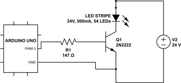
The Arduino can only supply 20mA of current, your LED strip will likely need a lot more current than that. So you would have to put a solid state relay or transistor (or MOSFET) on the pin instead of an LED.
Circuit would look similar to this:
i have always been confused by this.
you need the same ground for both the controller and the led, but you led isn’t controlled at the same voltage than you arduino…
Can you connect ground of separated power-supply with different voltage and amperage together without issue ?
How do I find the mA rating of the LED strip? It’s not in the documentation, hard copy or online, but it seems to be running just fine at full brightness when I plug it into the the 5v power pin.
I would assume to control the level in code via analogWrite(pin, 0-256). How important is the resistance for the transistor? And this might be a really stupid question, but I would I need to provide an external 5V power source apart from the UNO or could I use the on board pins?
Depends on the power supply. Switchmode and linear supplies should have a transformer isolated output, meaning their Ground is different from earth ground.
Mostly yes, you can just common grounds together (as you do in a computer with the various rails).
Easiest way: Multimeter in series with the strip.
yep
In case of the 2N2222 transistor running from an Arduino, the resistor is to protect the Arduino more than the transistor. Unless you know the current the LED strip draws, the resistance of R1 is a lucky guess.
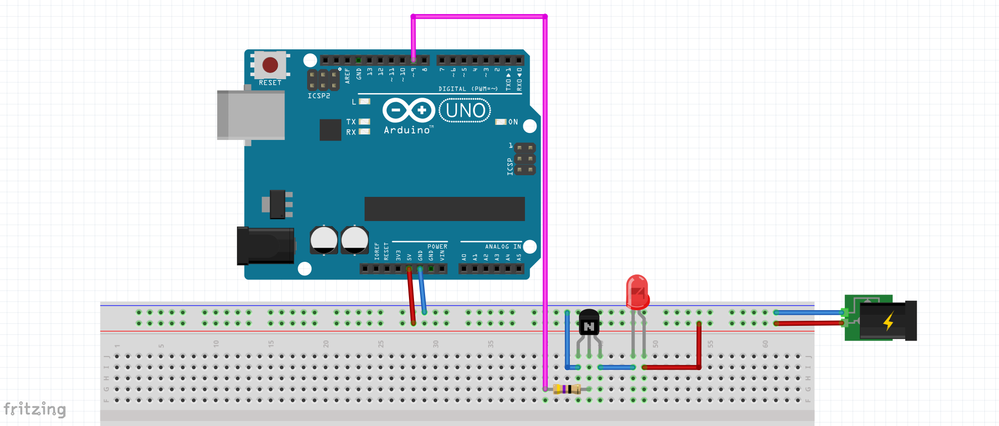
The way to hook up an Arduino when it deals with high current loads is to build a “bus” for power (5V) and Gnd. Then you hook your load into the bus with the Arduino in paralel. Just unplug the Arduino from 5V when you hook it up via USB.
Like so:
(The single LED is a stand in for the Strip. In this application, it would see an “unlimited” current shortening its life span).
Out of curiosity, is this Arduino being used for a project and you want to incorporate the LED strip? If so the above info is great.
Often times I find on posts like this where the goal is X (in this case dim an LED strip) and the first thing that comes to mind is Y (Arduino everything) so it gets presented as X+Y. It’s virtually impossible to divine someone’s goals from a brief post, but I tend to err on the side of too much info vs too little.
If you only need to dim the light there are various ways of doing that, from adding a resistor or using a lower supply voltage, to adding clear tape and coloring with a Sharpie or diffusing with a translucent cover. Just a few ideas since an Arduino is a bit overkill for only dimming an LED strip.
If it is a part of a larger project, share it! I know I’m guilty of never taking pictures of my crazy projects.
It is. @MazeFrame gave a lot of good and relevant information.
IDK how big the overall project this would end up being, but the main goal of this would be to get the arduino to receive an input from a raspberry pi or small computer that can A) manage a bunch more devices if need be such as a motion sensor, extra LEDs, speaker, light sensor, microphone, etc, and B) act as an private http server so I can manage all of my devices from a web interface or a simple app on my phone. With this I can have the LEDS, lights, and fans be more effectively controlled by me either with automatic scheduling, proximity detection, or manual control through a web or touchscreen interface. Plus it would be a really good project to show on a resume, flex on friends, haters, and the many girls that may or may not walk in my room. Wouldn’t it be absolutely sick to walk in your room, have a raspberry pi detect your presence, bring the lights up/down to an amber glow and have Marvin Gaye-I Want You to fade in from the background? XD
As a well seasoned programmer, I can do (and have been doing) the frontend, building and running a flask server on the raspberry pi, and provide inputs and outputs to and from a pi (in python) and an Arduino; pretty much everything except the hardware portion of the LED strips. I have had this Arduino since I was 12 (it actually was the thing that started me out in programming), though I haven’t done much with it. Over the past couple years in college, I’ve been doing more IEEE workshops where we do a bunch of soldering and electrical board stuff. It’s a great introduction, but hopefully this project will help me get off the ground with a good foundation of Arduino tinkering and electrical engineering.
Might want to look into I2C then. That way you can have addressable devices (LCDs, sensors, etc.) on a bus. The Wire library for Arduino makes that almost too easy.
Concerning connection to the RPI, do you use some sort of bus (I2C?) or have an Ethernet shield on the Arduino?
Yep. I want to do DIY-everything automation at some point in my life.
No, just connecting via usb. I’ve got a python script and an arduino project working where I can read/write via the serial monitor. It doesn’t seem like the most elegant solution, but it works well right now and I can already implement it.
Do you have any resources like YouTube videos/series/channels, online tutorials, or just good sources to go through to get off the ground regarding knowledge of the hardware portion of Arduinos/RPIs? I figure it’s like programming, once I break a point I’ll have the knowledge to ask better questions and have a more foundational understanding on how everything works.
If you just want to get this working, home assistant, provides B).
For A) you could use an esp-01s board (<$1 on aliexpress - widely available everywhere) that has both wifi and pwm*, and flash it with firmware generated by ESPHome to get its wifi working and have it integrate into home assistant.
You’ll still need an amplifier for pwm of some sort, a suitable bjt or mosfet to drive the led strip from the pwm output of the microcontroller.
* esp8266 doesn’t really have hardware pwm, but it’s commonly emulated in software – for something like 1000Hz which you may want to use on LEDs it’s good enough. For 25kHz that you may want to use with 4-pin PC fans you’d need an esp32, or another solution like a pca9685 i2c->pwm breakout
I just looked stuff up for the specific problem I tried to solve.
The Arduino website has some Basics on the boards and software and what is essentially a reference for all the other knowledge related to the board.
Related:
I am currently building an individual addressable LED strip setup for my bedroom.
I use WLED with the QuinLED-Dig-Uno (which I chose because I did not bother to assemble the board myself, but there is plenty of DIY compatible hardware).
WLED integrates nicely with Home Assistant, which I plan to do.
Not all parts are here yet, and if anybody is interested I can do an update as soon as it is finished. ^^