I used a pre-programmed exercise to confirm the servo in the back has no issue moving the cable to change resistance, an incline calibration in the menu to confirm that motor works.
Took some stuff apart and the little buttons on the arms are good ole’ clicky momentary switches that are in working order (resistance tests).
Took some measurements and it’s a 3.3v signal X2 going to the switch and a ground wire. One 3.3v to ground = up, other down. At least I think that’s the intent, it does nothing.
I even pulled the 3.3v to ground I found on the board but nada.
Is this a problem with whatever IC is being used to tell the android brain to change the resistance?
I also noticed when it’s not working, the “short cut” resistance capacitance buttons in the center console do not work either.
I’m at a loss. I was thinking the 3.3v would be dicey and explain this issue, but it’s solid. Maybe it should be 5v but this is a sign of the IC dying?
Was hoping an easy voltage regulator or burnt resistor fix was in order, but I think this goes deeper…
So up until the twenty teens, most Logic ran on 3.3v, with the odd system using 5v. If you supply 5v, you will more than likely kill it so don’t do that.
If it is second hand, more than likely something happened to it, like corrosion, moisture, or the like. I would look for burned traces, or corrosion, or water damage first. If everything else seems to be working, it is more than likely not the IC. If you can find the trances, you can bypass them and go to the IC and see what happens.
Unfortunately, there is not enough information to really help you troubleshoot. Maybe see if there is a repair manual for this thing out there on the NordicTrack site?
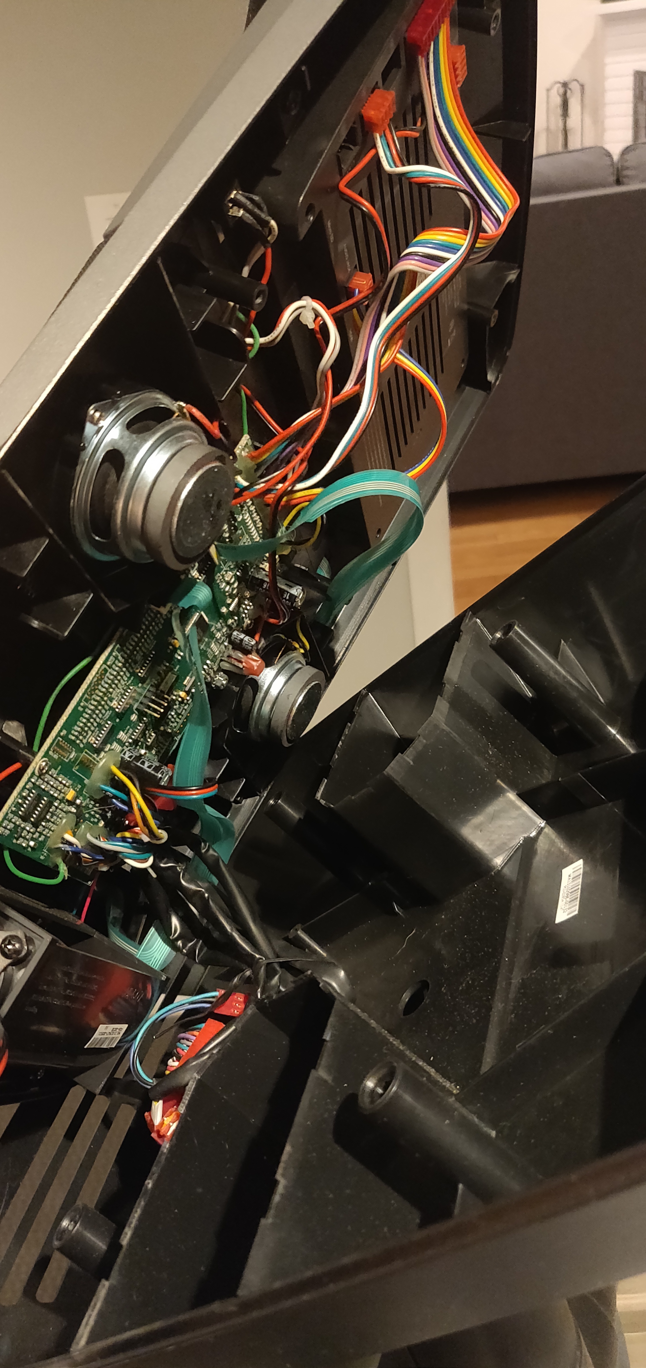
That’s the thing, I got down to the actual PCB solder points that go to the switches, and found a legit good ground on the PCB, and “shorted” the various 3.3v high sides to said ground directly therefore replicating what the switches would be doing but cutting out all of the middle men parts.
Nada.
So it makes me think the internals of whatever IC is being used as the drop down detection of its own 3.3v out is going bad.
Additional notes:. Did a workout yesterday and used the capacitance keys this time to change resistance, the hand bar buttons didn’t work. So I guess it’s a good thing the capacitance buttons are going to a totally different controller that then talks to some brain as to telling the android screen what the resistance is at plus putting the servo to that setting.
Then you are probably right then. They should eventually reduce down to the same point to actuate the motors and what not. Maybe look for a cheap brain on ebay as a replacement?!
Yeah a better techie could probably do circles around this thing and take this as an opportunity to upgrade. I think I’ll rock the quick settings buttons for now as I’ll likely brick something if I work on this more.