Hello!
Allow me to tell you a bit about myself, my name is Chase I'm in high school, I primarily play RTS and Flight sims last year I built my first computer and I'm currently studying what I can about 3D printing in preparation to try to design and build a 3D printed flight-stick, what does that have to do with you??? I... Honestly don't know, but what I do know is that I could use some help with my idea for a 3D printable HOTAS
Here is what I need (ill mark this out or add to it as I get the info and help I need)
If someone with a HOTAS system could provide me with the measurements that I've outlined in the lines at the bottom, then that will allow me to scale my design the match what's commonly in use (as many different makes and models would be best for averaging purposes)
Ive included a sketch of my general design and would like some suggestions on how I could improve the ergonomics and streamline it for 3D printing (I'll be getting some clay in a little while to model it by hand (unfortunately I'm no good at cad so clay for me)
I'll also need some electrical and mechanical advice from people with more expertise than I have
I intend to get my 3D printer at the beginning of next year and am still deciding which to buy (I'm still deciding which to buy, however, as I'm trying to find a part-time job so ill have some cash to spend on stuff like this I'm trying to keep the price down to less than 500 (preferably less than 300) so I can get plenty of filament and any other parts I end up needing.
Lastly, any advice about 3D printing filaments and methods is welcome I'm doing what research I can but balancing school, getting the necessary hours to get my license and the fact that Christmas is just around the corner does not help things
1 the measurements that I need are as follows
The length of the flight-sticks grip (from the connection to the base to just under the trigger)
The circumference of the grip at its thickest and thinnest points
The travel distance and width of your throttle as well as how many buttons are on it
PS. if anyone knows a way to calculate the strength of a printed part besides trial and error, then please link me as that would be useful when designing the base
PPS. I'll check back as often as I can but I might have periods of a day or two where I'm just to busy or don't want to deal with the world so you might not hear from me.
Thank-you for your time and help.
~Chase
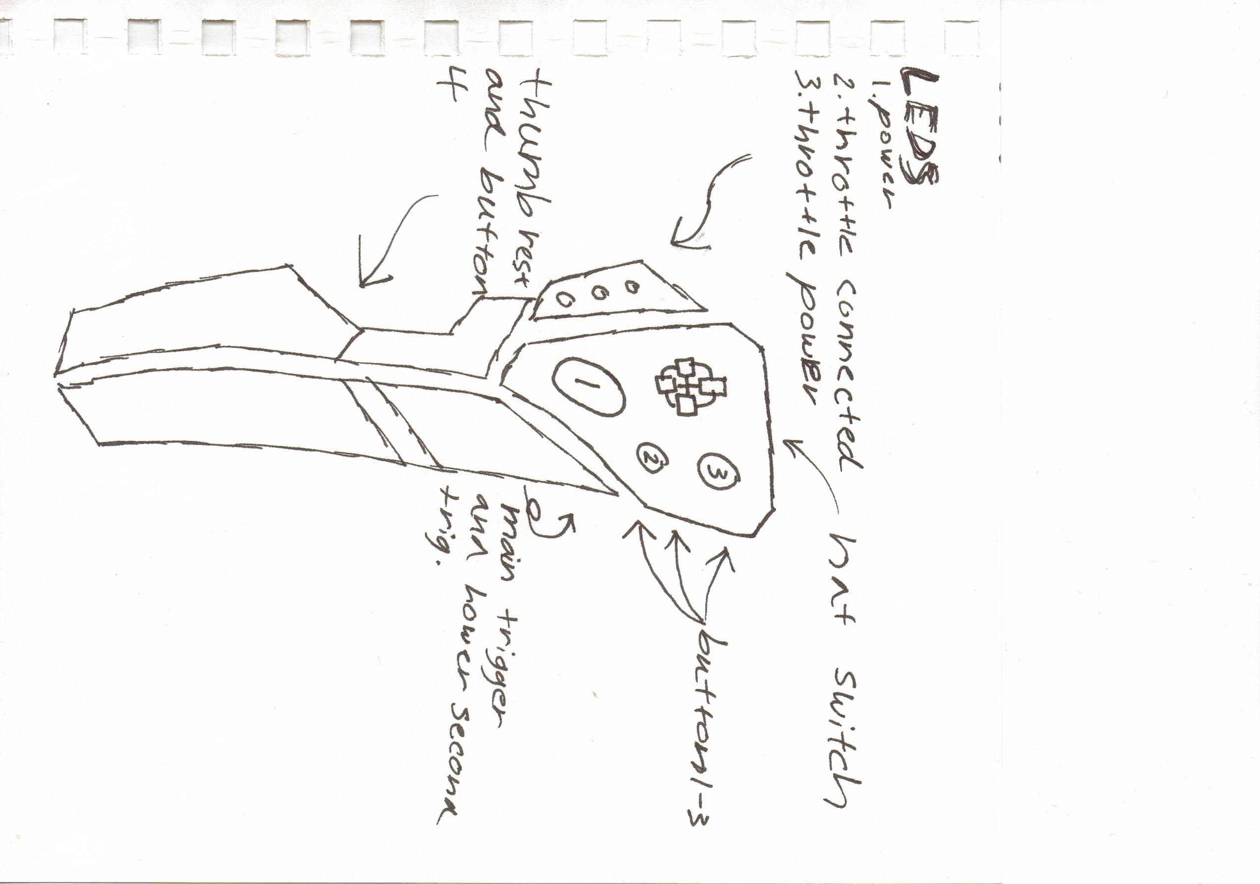
Flight stick design sketch
.
.
.
.
.
Update 01#
I found some time today to work on the design for the base and here is what I came up with, the questions I had about them and the problems that I could foresee when building each.
I stared with around ten ideas (four gimbal designs a couple ball in socket designs and some impractical designs I came up with for fun) here are the two that made the most sense.
Idea 02: This was the simplest of my gimbal designs and the most practical.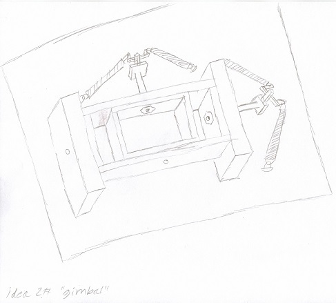
.
.
Idea: 04: the two "ball in socket" designs ended up being more or less identical except this one used a hollow shaft(and my drawing was cleaner :P).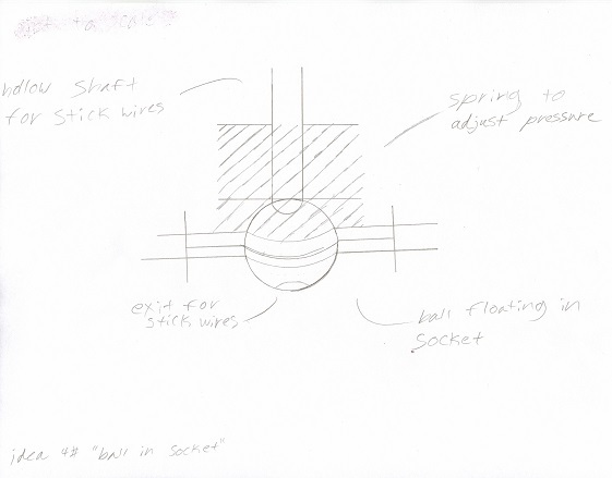
Okay so pros and cons, well lets break this down one at a time shall we?
the pros of the gimbal design are as follows:
- Its easy to print and build, all of the parts in this design are either strait horizontal or vertical which should help with the printing process as well as allow some room for error when putting everything together.
- the fact that it uses multiple springs allows me to customize the pressure required to pull the stick in each direction (for instance id like it to require less pressure to roll then pitch).
Cons:
1. Strength, although I'm sure that with the right materials the actual the hub will withstand plenty of wear and tear the parts that connect the bolts to the balancing springs might wear down over time and break off.
2. Size, now I know they say size doesn't matter but in this case it does this is going to be a sim-desk setup so the stick should be as unintrusive as possible and to keep the construction at a reasonable strength I think that it might end up being bigger then I want.
Now for the ball in socket
Pros:
1. strong, my local hardware store sells "ball in socket" connectors that I could modify to work the same way as my design, the upside of this being that I don't have to worry about a breakage occurring in the axis assembly, although I will nee to figure out how to attach it to A 3D printed base (I think an epoxy should work)
Cons:
1. Tracking, I have a few ideas in how I can track the gimbal style if axis but with my admittedly limited knowledge of servos and electronics I'm afraid that I've drawn a stop as far as this design is concerned.
2. Although using a single spring simplifies the assembly process it means that I cant have different pressures for roll and pitch.
any input or criticism of the designs is welcome, also if anyone has any ideas on how to track the ball in socket style axis pleas let me know.
On a side note I've dropped this on the LTT forum and was looking at dropping it on the Robert Space Industries forum aswell (a friend mentioned that there is a guy on there working on a similar project) anyone have any suggestions as-to where else I should drop it?
.
.
.
.
Update 2#
Okay so its been a while since I made an update and in all honesty between the short vacation my family took and the sickness, I caught while we where away I haven't had as much time as I would like to work on the project however I've reached A point where It seems prudent to make an update for you all so here it is
So what have I managed to accomplish in the month or so since my last update?
Well, I ended up both simplifying and expanding my project, how you ask? Well, allow me to explain what my original goal was:
Stick: so the goal for the stick was simple: a primary and secondary trigger, hat-switch and a thumb button for bombs/Rockets
Throttle: so the throttle was supposed to be the simple part of this equation, it was supposed to have maybe one or two buttons and plug into the base of the sick
So what have I changed?
Well to start off with I've decided to add rudder pedals simplify the design of the stick and add more buttons to the throttle
Why add ruder pedals you may ask?
Cuzz yaw control mate!
The reason I decided to simplify the stick is that I wanted to add a wrist rest for long sessions and didn't like how my current design looked with it tacked on.
As for the throttle my original plan was to use a "pot" in the grip and a rocker to control rudder, I still might do that but for now I'm just going to go with a separate rudder unit and a simple throttle.
Ok, time for a brief explanation of what I had originally and what I've done to improve each part
Pedals:
We'll start off with the pedals as they are the newest addition to our little group
After a lot of searching and failed ideas (I'm halfway through a package of printer paper) I ended up tossing an email at the good man over at SlawDevice and he gave me permission to copy the design for his centering mechanism (THIS design, not his new one) ill be using a slightly altered version of it for my design.
Although I haven't had time to do much more than sketches I did manage to stop by my local hobby shop and pick up two things, one being several sheets of foam-board and the other was a pack of potentiometers.
Now that I have a general idea of the size and durability of what I'll be working with I used some of the foam I picked up to put together a simple testing platform to find out things like "how many degrees should it travel" and "how wide should it be?". during my testing I found that a distance of around 380mm between the center of each pedal with the pedals sitting parallel at a distance of about 6-8 inches from my chair (my chair sits at a height of 19 inches) was more or less perfect for me, however when my brother tried on my test rig he didn't find it comfortable till the distance between the pedals was 475 with a slight angle so that his toe was facing outward and the were pedal cockeyed so that the inside edge was higher then the outside edge, we also moved the pedals back by about 4 inches. (hes a 6-foot something or another mammoth)
So, what does this mean for me? well it means that either ill have to put the pedals on some-kind of gimbal to allow you to adjust the angle or just leave them parallel and call it good enough.
Stick: Aside from deciding to simplify the stick Ive also tried to take into account the fact the Ill be playing primarily sim battles in war thunder and IL-2, which means long sessions.
So this means ill want function rather then form (Yeah an angular stick will look nice but my current design doesn't have a wrist rest and due to the gaps between the plates wont be that comfortable for hour+ sessions of game-play) so what do I intend to do to improve on the stick? well ill be adding some-kind of wrist rest and either go for a 109 style grip with simple lines and no frills or switch to a floor mounted setup and use a yolk similar to the spitfire or early Russian fighters from WW2
Throttle: after spending around an two hours looking at and sketching out different designs I came down to one question, what do I want my throttle to do? well I want it to be desk mountable have buttons or switches for flaps, gears, engine ignition and shutdown aswell as couple extra just incase I decide I want to bind anything else.
So how many buttons and switches do I want/need? well my intention is to attempt to use a pair of LeoBodnar BU0836A (one for throttle and the other for stick and pedals) so after subtracting the inputs taken up by the "pot" Ill have 28 available inputs for buttons and for my uses I think four toggles and 6-8 buttons should work nicely.
Well folks, that's all Ive got for now.
Starting the 21st I've got a pretty busy schedule (three birthdays, Halloween, and a bunch of family stuff) so you might not get another update until December when things usually start to slow down a bit before Christmas.
.
.
.
Until next time
Chase~
.
.
.
Hiatus
Just a quick update for you guys,
I unfortunately have to call for a hiatus until further notice, I intend to continue working on the project, however, some IRL things came to a head quicker than expected and I don't know when i'll be able to devote the time that this project deserves.
So sorry.
Chase~