I have a router that needs serial recovery to fix a soft brick. I have everything disassembled, and just need to make sure I’m using the multimeter right to determine, which cable corresponds to which pin.
So, I turn the multimeter on, switch it to AC, and touch both probes to the same pin till I get a 3.3v reading and 0 for ground? Should my router be powered on for testing the headers?
You need to set the meter to DC. On AC, ground and power are switching constantly.
The black probe goes to GND (= ground / 0V), that can be the housing of a USB header or a pin/pad labeld as such.
Then you can move the red probe arround to see if you get readings. For example the housing of another connector should also read 0V.
Yes, to read more than continuity, the circuit has to be “live” (in this case, probably 9 or 12V).
When you look at the case where the power supply plugs in, you might see something like this
It tells you which part of the plug is what.
Ok, so I place the black probe on what I believe to be ground, and test the other 3 pins with red till I get a 3.3v reading. How can I verify I don’t have GND and 3.3v flipped?
if you are using a digital display meter on dc and have the polarity switched it display a negative sign before the value, If you are using an analog meter (dial face with a needle indicator) the needle will swing in the opposite direction from zero (meters generally read from left to right so a reversed polarity will cause the needle to swing left)
bridging contacts means when your probe makes contact with more than one solder joint or pin!
this can in some cases cause a damaging short circuit.
So, I’m pretty sure the left most pin and furthest right are 3.3v and gnd respectively. But, I’m not certain I tested the pin outs correctly. My test methodology involved: powering on the router, switching to DC mode on the multimeter, selecting 1 out of the 4 pins for gnd, and then testing each of the other 3 pins till I got about 3.3v.
Since then, I’ve read gnd can be found by choosing a known ground point on the router, and with the ROUTER OFF testing for continuity till receiving a reading of zero on one of the pins.
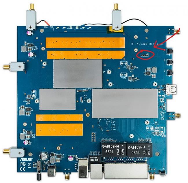
Were my tests performed correctly for finding gnd and 3.3v? The pinout diagram, which I believe is for the serial port on the unit, has different readings.
If I wanted to double check for gnd with the continuity test, based on the image, which metal bit on the router would definitely be gnd? (the housing is all plastic) Can I just use the side panel of my pc for gnd, which other common household objects would work for gnd?
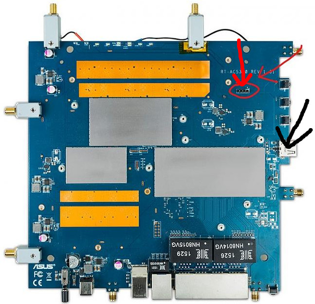
To test ground you would leave it unpowered and put one probe on the pin and the other on something like the metal shield of the USB like the arrows indicate. You should get a beep indicating there is continuity, meaning they are connected electrically.
It sounds like you did indeed find your 3.3v and ground correctly.
Yes, all parts connected to the ground plain will give a reading of 0 ohm or very close to that (continuity mode). That way you can find the ground pin on the power header.
Then when the device is powered up, you can reference your other readings to that known GND-pin.
^this, kind of hard to explain. Use whatever explanation makes more sense to you.
the reasoning for this is sometimes a component can backfeed a ground bus when under power
giving you an erratic reading for a short time until the capacitors drain down.
for example a microwave oven the power capacitor can hold quite a charge for up to an hour or more that can blow a meter out when testing continuity or ohms.
and a crt anode can carry an almost and sometimes lethal charge for 2 or more weeks!
hence the reasoning for the discharge probe and chasis ground clip.
yep i worked on tv’s for a few years!
thats understandable but using a dmm it can pick up small voltages that have very minimal current
usually from induction and unless someone knows the whats going on they will be scratching their head trying to figure it out.
anyhow research on the web can usually find the schematics for the devices easily.
Not sure about finding schematics easily, you can usually follow the RX/TX traces to the soc ; (should be middle two on your router)
The squared off pin (right on your picture) is 99% of the time pin1, which is vcc 2 out of 3 times (my brief googling suggests that one to be ground in your case).
Note that you need a 3v3 serial adapter, not all serial is 3.3V . Connecting the 5V or +/-12V serial can fry your router soc. (raspberry pi headers have a 3v3 serial that works great with minicom under Linux, if you happen to have the new lying around).