Aha, I thought about that! If you look on my second image posted, you can see I actually drew which PCI slot pins connects to the 12v rail, and the other gnd (and other connections). Used Wikipedia for reference on which pins are for what to help me out a bit.
The reason for not soldering directly to the PCI card pins is because if I ever wanted to reverse my work (unlikely, because it’s an old ass PCI card), I could desolder everything and plug it right back into a PCI slot.
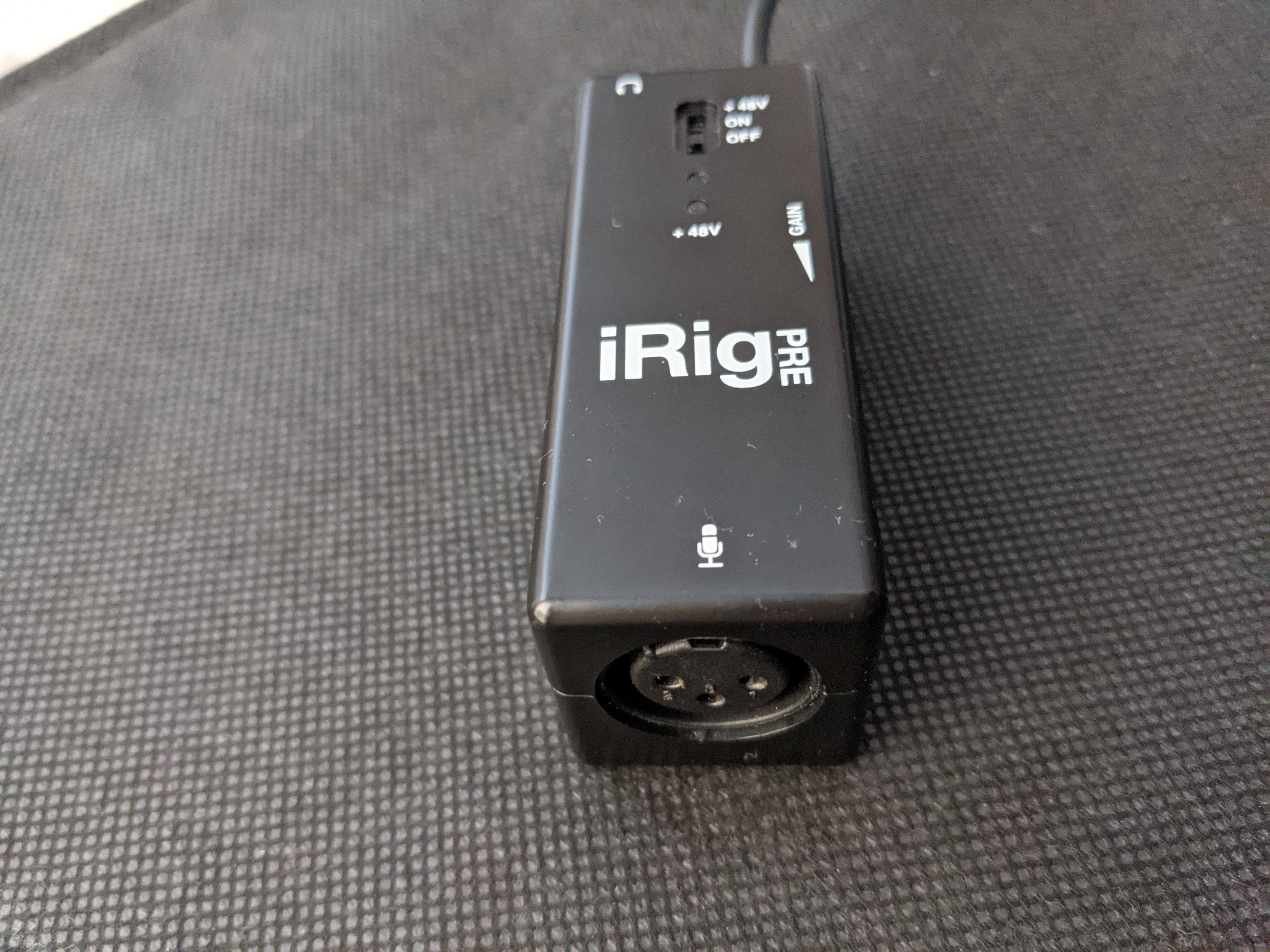
I bought an iRig Pre (preamplifier) that I wanted to make it work with 3.5 jack microphones.
Unfortunatelly this thingie (the preamp) seems only compatible with self powered microphones or it can provide phantom power.
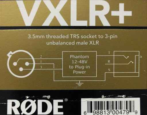
But I don’t have a phantom powered mic and I don’t want to use one, so the only way (to make this preamp work with standard 3.5 microphones) I found so far was to buy another piece of equipment like VXLR+ which takes 48V, steps it down to 5V from LXR connector to 3.5 jack connector.
So I would like to know what do I need to do in order to provide the required 5V to my microphone to make it “produce” sound that the preamplifier could use.
Some extra details…
iRig Pre has a 9V battery in order to work. It has a ON switch which unfortunatelly doesn’t output any power and a +48V switch which would send 48V down the XLR connector. (which I won’t use because I understand this could kill my microphone).
My test microphone is a Rode VideoMicro. 3.5Jack TRS connector.
So I do have multiple questions in my head, but what I want to know firsthand is how to step down from 48V to 5V in order to power my mic?
I could as well try to get power from the 9V battery directly if a step down could introduce extra noise.
How is Rode doing it in their VXLR+ adapter?
And most stupid question… I don’t understand the difference between an amp and a pre-amp, if my iRigPre is the preamp, but I can’t power the passive microphone, do I need an amp before the pre-amp to power the microphone?
Using a buck converter (whether it be from 9v → 5v, or 48v → 5v) would likely introduce noise (unless you choose a very low-noise buck converter + the right capacitance + inductance values). A linear regulator would likely be a better bet, but uses a lot more power.
A basic LM317 linear regulator could drop the 9v down to 5v, and would introduce significantly less noise than a buck converter. A linear regulator that would drop 48v to 5v would likely be more difficult to find (and more inefficient, I’d imagine). However, before you try either a buck converter or a linear regulator, I recommend you first inject 5v into the microphone via 4x 1.5v batteries (AA, AAA, AAAA, etc.). If it’s slightly above or below 5v, you’ll still be fine.
@MazeFrame 's comment in this thread (here) about injecting 5V into the microphone was very helpful for me. You’ll likely need to design a very simple circuit that removes the DC bias. That’s what I did here. The brown PCB provides 5v to the microphone, with capacitors + resistors used to remove DC bias and limit current. The blue PCB (TDA2030) is a simple amplifier (designed to power speakers; instead I used it to amplify a microphone signal).
I personally do not have experience with it, and TBH had no idea it was a thing until you brought it up. Cheaper alternatives exist on EBay, but I doubt they’d sound as good as Rode’s.
TBH, neither do I fully. To me, it seems like they’re both used interchangeably? Maybe @MazeFrame would have the answer. I think a pre-amp is more specialized in boosting ultra-low signals to usable signals (while introducing little noise), that can then be further amplified via a regular amplifier?
There are a few different microphone types AFAIK (maybe I’m wrong?), and some require 5v to operate, while others require 48v, and I’d guess there may even be microphones which require no voltage input (ie. speaking into the microphone creates a signal loud enough to be amplified by the pre-amp). It seems that your iRigPre simply doesn’t output 5v.
There are 48V to 5V step-down adapters (as you found yourself already).
Or you copy what @TheAlmightyBaconLord built and hook that between mic and iRig Pre (without throwing phantom power at it).
Good question. If I had to guess, two stage linear regulator or some specialised linear regulator (AFAIK normal ones top out at 37V input voltage).
Amplifiers in general put power into a signal for headphones or speakers (or antennas, different topic).
Main difference here are power amplifiers (sometimes called “power stages”) and integrated amplifiers. The integrated amplifier is a combination of pre-amp and power-amp.
“Pre-amp” can describe two things:
Input selector and volume control to go between source and power amplifier. It is “pre” as in before the amplifier
amplifier to get signals up to so called “line-level”. To reduce confusion, these are often called “phono preamps” (for record players) or “mic preamps”
Correct.
Dynamic Mic - no phantom power required, but usually require a beefy mic-preamp.
Condenser Mic - Usually require phantom power (in 90% of them, 48V)
Electret Mic - Require somewhere between 2 and 9V phantom power (check manual/spec sheet!)
Thanks, I followed the entire thread, but not sure how to add 5V to the mic. I do have boosters/power sources plenty around, so I can use one.
So if I got this right, I need to add 5V to the ring of the mic and ground to the sleeve while leaving the tip untouched?
I was under the impression that if I use a multimeter on the tip and the ring it will buzz me, so I thought that the mic was actually shorting the pins. Maybe is actually buzzing because there is a coil?
On a side note, I managed to crack open the iRig Pre and inside there is
R45801 - I assume is a TI RC4580 ? : www.ti.com/lit/ds/slos412d/slos412d.pdf
MC34063A - ONSemi MC34063A www.onsemi.com/pub/Collateral/MC34063A-D.PDF
The specs for the MC3406A states it can do “Operation from 3.0 V to 40 V Input” so not sure how they manage to stretch that clean 48V I’ve measured as Phantom power.
Also the MC3406A is featured to be working as Step−Down and Step−Up and Voltage−Inverting. Letting aside that I don’t know what is Voltage Inverting and what is this useful for, I wonder if it would be an easy job to make the regulator to work as step down to 5V and not a step up to 48V.
Assuming your particular mic has the same pinout as the default computer mics:
Put current limited 2 to 9V (could add a potentiometer that can handle >5mA to adjust this on the fly) on Ring, then couple signal from Tip through a 100nF to 1uF capacitor to get the signal without the bias voltage.
Could be configured for “Dual Mono”, in that case you alter the above schematic to apply the bias voltage to Sleeve, short Ring and Tip together before coupling through the capacitor.
Nevermind, I didn’t understood this first, but then I’ve found some pictures on the internet explaining that the thick line in the left and the V and A symbols actually are the 3.5connector.
Also found some page explaining stuff and realized the old way and the new way of doing it (written on the yellow stickers), seems that those days both tip and ring are shorted. tuxgraphics.org/npa/condenser-mic-on-usb-sound-card/
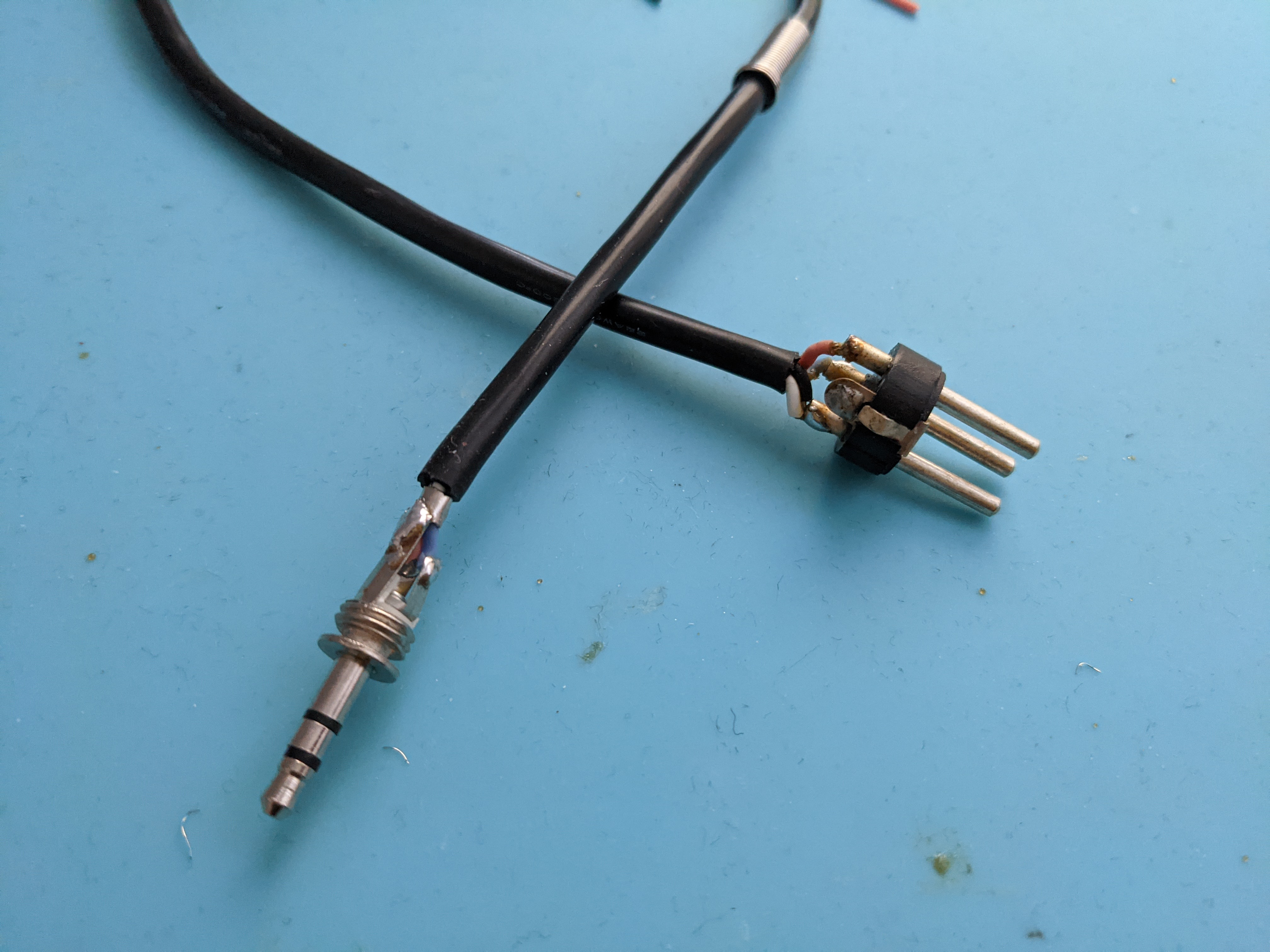
I will try to add the 5V voltage somewhere on my custom cable, but before the capacitor.
In the above quick drawing done by @MazeFrame the right 10kOhms is between the line and ground? (There are two circles, one under Audio, and one circle after the 10k resistor, that second circle is the ground?)
Thanks!
I know I ask some stupid questions, btw, so have mercy.
Cascade them. In theory, this should work: connect the gnd/adj. pin of the first 317 to the output of the 2nd 317. Then connect the output of the first to the input of the 2nd. Add capacitors for stability.
Alternatively, use suitably dimensioned zener diodes in the gnd/adj. line from the first 317 instead of connecting it to the 2nd one. Still requires capacitors!
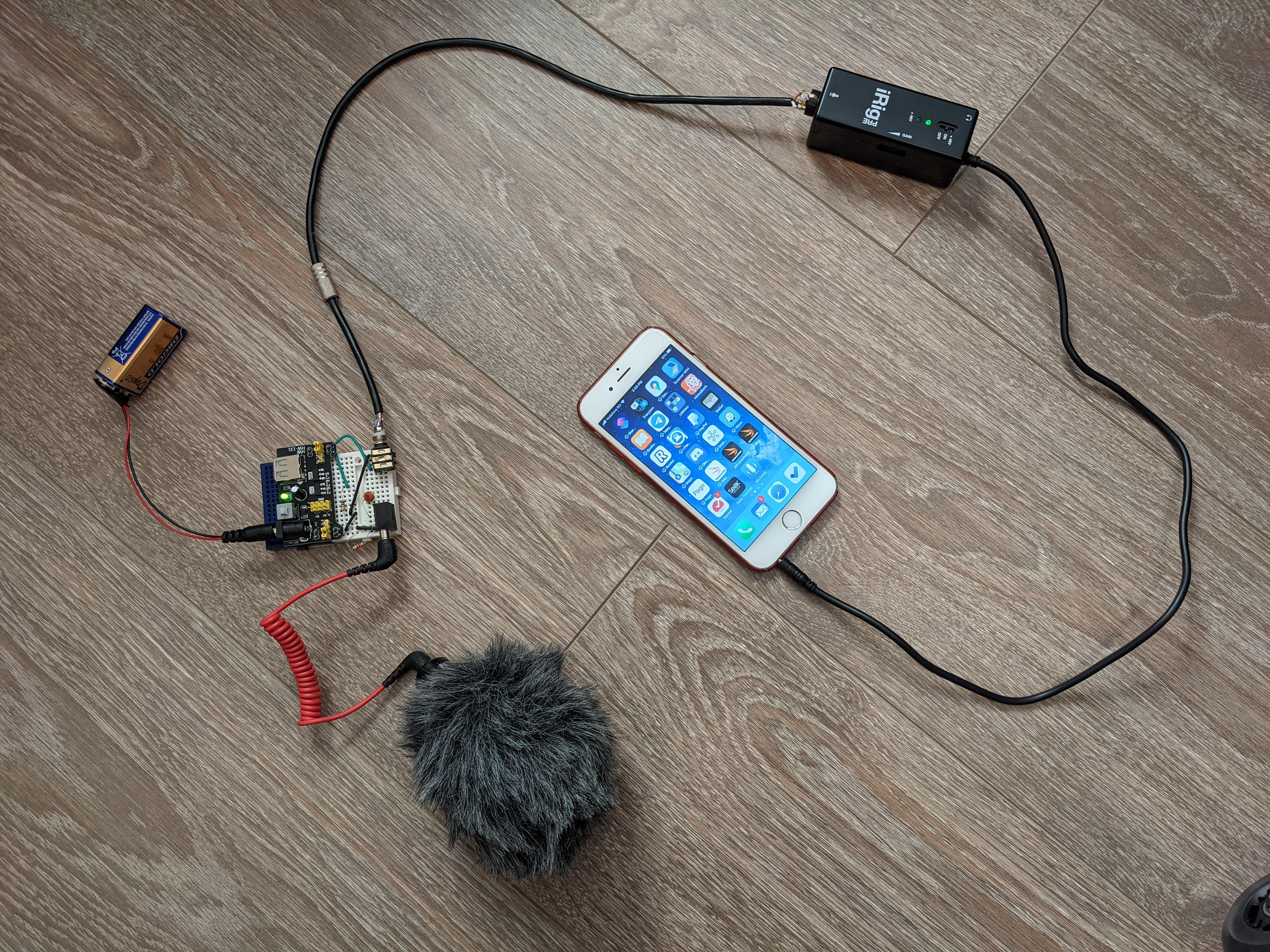
Yuhuuuu!!!
I managed to make the mic working by following the hand drawn schematic from @MazeFrame.
I’ve used a 2.2K resistor as I had no 2K one nearby.
For capacitor I found only one marked with 104, I assume is a 0.1uF cap.
And I connected everything to the tip, as the tip and the ring are internally connected anyway in the Rode VideoMicro.
I’ve did a quick recording on my iPhone, seems to work but the recording seems to be kinda noisy, some background buzz is there. I could try to adjust a bit from the iRig Pre wheel for setting the gain, but except that, what else could I do in order to improve the sound?
Adding more electronics, changing resistors, a bigger cap?
Thanks!
Stumbled on this video https://youtu.be/_SAUK_wBhp4?t=50 (at second 50 you can see his schematic). If you look in description there is a link to a page with more details.
Also found the internals exposed for Rode VXLR+, and other adapters, schematics and other pictures.
I don’t really understand how those Zener Diodes are working, but I assume those works because the used current consumed by the microphone is very small, right?
So they don’t use any regulator at all, just resistors and diodes… Can someone shed some light on this?
Wow that is not how I expected them to drop 48v to 5v! No regulators at all!
So those zener diodes are clamping the voltage to 5v, and using a capacitor to smooth it; without the large electrolytic caps, the voltage would be oscillating between 48v and 0v.
Considering how simplistic the schematics are, I did not expect the adapter to be $30+.
 Farnell, RS, AliExpress are among your options there.