Tek Syndicate Standard Issue Mouse LED swap
Rev 1.0
If you are like me, and have just received your new Tek Syndicate "Standard Issue" gaming mouse, you’re probably excited. This is my first new mouse in a very long time, replacing my 10+ year old Microsoft optical mouse. Yes, it has been that long since I bought a mouse for myself! The only issue I have is one of aesthetics; the purple LEDs do not match my build. Let’s remedy that situation, shall we?
First, let’s have a little discussion. I would rate this project as intermediate level. So, what does that mean? Well, this project will be much easier, and have a much greater chance of success, with some specialized tools and knowledge of electronics. While I would be more than happy to discuss how to use of these specialized tools on an individual basis, this is not a tutorial on how to solder, electronics 101, or how to use a digital multimeter. I'm sorry, I wish I had the time to include all of that information, but this guide would increase exponentially in size. Please, if you need any help with some of the details in this guide, post in the forum, I'm happy to help.
Second, I'm just a regular guy that loves to tear things apart for ridiculous reasons. I am not an electronics major or a professional writer. I have experience with the tools and methods used in this guide, that's it. In short, if I can perform this modification, so can you!
My wife said I was crazy when I told her I was going to tear apart my new mouse. While I certainly understand her point of view, and the risks involved, I decided to proceed anyway. Risks you say, what are the risks? Simply put, you risk destroying your new mouse beyond repair, as well as other horrible things I cannot foresee. If you can't afford the risk of destroying you new mouse, DO NOT perform this modification. I will do my best, in this guide, to point out potential problems and make the information contained herein as accurate and safe as possible; However, I can't predict every possible scenario. That being said, by using any part of this guide, you assume full responsibility for any outcome that may occur!
Now that the pleasantries are out of the way, let’s get down to it!
What exactly are we going to do? This project will involve removing two LEDs from the main mouse circuit board and replacing them, along with their appropriate resistors. Optionally, a third LED and resistor can be added to the DPI board; see my thoughts on this at the end of the guide. For the purpose of providing concrete numbers for this guide, I will be using red LEDs.
Parts. The parts and consumables needed for this guide are simple: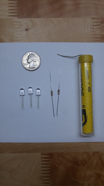
2-3 5mm LEDs. Two LEDs are required, and must be the same color. The third LED is optional, and may be different in color than the other two. We are talking about single color LEDs here, not RGBs. The board is set up to accept RGBs, but, from what I can tell during testing, the electrical connections are not present to operate them. This is probably a stock circuit board, or a hint about things to come, who knows. If you must try RGBs, go ahead, but it is beyond the scope of this guide.
1-2 resistors. To keep your new LEDs alive, resistors must be used. One resistor is required; the second one is only needed if you are installing the optional LED.
Solder. For installing your new LEDs
That's it for the parts. Let’s talk tools!
Tools. We all love tools. So let’s talk about them. I'm going to group the tools into three categories, required, recommended, and optional.

Required tool: The build cannot be completed without these tools.
Small phillips screwdriver. If it is small enough to remove the screws holding the mouse body together, it will work for the entire build.
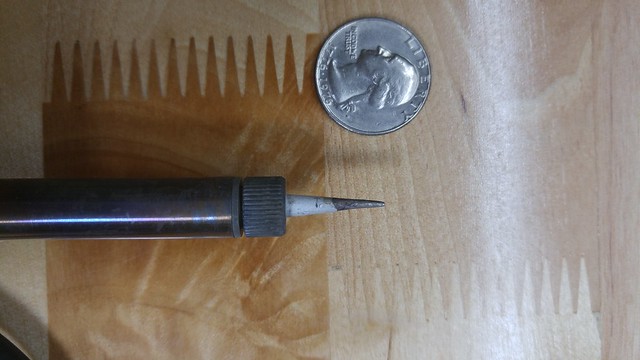
Soldering iron. One with a thin pencil tip is preferred; it will need to reach some tight spaces.
Small needle-nose pliers or tweezers. Something to grab the LEDs with during soldering and de-soldering.
Small wire cutters.
Recommended tools: Increased success rate.
Helps maintain sanity. Tackling this build without these tools is like a soul level one play through of Dark Souls. While it is possible, the odds are stacked against you!
- Digital multi-meter. (DVOM from here forward) It should be capable of measuring DC volts, resistance, and continuity. This project can be completed successfully without a DVOM. But, the risk of failure increases greatly. YOU NEED A DVOM! If you don't have on, buy one. If you can't afford one, borrow one. If you can't borrow one, you may have a bad time with this build. Don't say I didn't warn you!

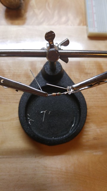
- Helping hand. Soldering aid, third hand, parts holder, they go by a lot of different names. Here is what one looks like:
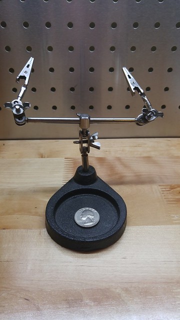
Soldering electronics requires more appendages than come standard with the human form factor; this tool will remedy that issue.
Small flat head screwdriver. Something on the same scale as the phillps screwdriver mentioned above. Nice for removing the friction pads.
Hairdryer. Also used to aid in the removal of the friction pads.
A means of testing your LEDs. There are many ways to tell the difference between the + and - leads of your LEDs, also known as the anode and cathode, respectively. The length of the leads, the flat spot on the side of the LED, examining the internal structure, these are all common methods for determining a LEDs polarity. I don't use any of these methods. Why? They are unreliable. I test all of my LEDs to determine their polarity. You can use a battery and some wire, 3.3 volts from an old ATX power supply or something similar. Power the LED BRIEFLY! Make note of which lead is which.
Optional tools: If you have the nice stuff, might as well use it!
Desoldering tool. I really need to get one of these. Helps remove solder from the holes in the circuit board, making it much easier to fit the new LEDs.
Breadboard and appropriate jumpers. Handy for LED testing.
Magnetic parts tray. For keeping things organized.
Did we come here to chat or tear things apart?! Let’s get on with it!
I'm going to break this down into three sections: disassembly, modification, and re-assembly. The steps for adding the third optional LED will be marked as such. If you do not wish to add the third LED, skip these steps.
Disassembly.
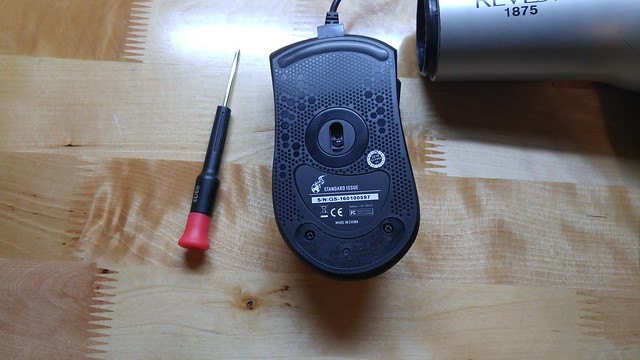
Step 1: Remove the two friction pads from the bottom of the mouse.
Using a hairdryer will help to remove the pads without tearing them. Heat them up and carefully peel them off. A small flat-head screwdriver can be used to pry up a corner and get the process started. Put the pads somewhere so that they don't get dirty.
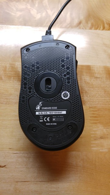
Step 2: Remove the 4 phillips head screws that were concealed by the friction pads.
Place them in your parts tray. Make note of their appearance. These fours screws are all the same.
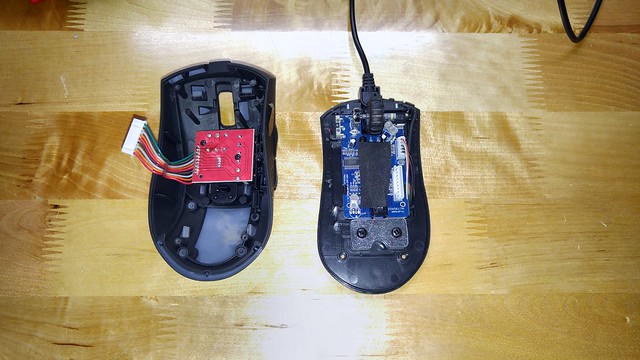
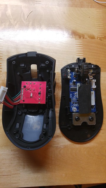
Step 3: Separate the top and bottom sections of the mouse body.
Be gentle, there is a ribbon cable connecting the top and bottom sections, and we don't want to damage it. The body should separate easily. If it doesn't, make sure you didn't miss a screw by mistake.

Step 4: Disconnect the ribbon cable that connects the top of the mouse to the main circuit board.
The connectors just pull apart. Grasp the wires close to the connector and pull straight up. Set the top of the mouse aside.
Step 5: Disconnect the USB cable from the main circuit board.
This is the same style connector as in step 4, it just pulls apart. Make note of the cable routing, then remove the cable from the housing and set it aside.
Step 6: Remove the single screw that secures the main circuit board to the bottom section of the housing.
This screw is different than the other 4 we removed in step 2.
Step 7: Separate the main board from the bottom of the mouse.
Pull back on the two plastic tabs, one on either side, of the bottom housing that clip over the edges of the main circuit board. While holding these tabs back, GENTLY pull the circuit board away from the bottom housing. The two should separate completely. Set the bottom housing aside.

Step 8: Remove the scroll wheel.
Pull the wheel to the right. It will slide right out. Note that one end of the axle is hex shaped; this is the portion that mates with the rotary switch on the main circuit board. This detail will be important during the assembly process. Set the scroll wheel aside.
Step 9: OPTIONAL LED ONLY
In the top of the mouse body is another circuit board; let’s call this the DPI board. There are two phillips screws holding this board to the top housing, remove them. These screws are different form any of the others. Keep track of which ones are which. Separate the top housing and the DPI board. Once again, they should come apart easily. Set the top housing and DPI board aside.
The disassembly process is now complete. Let’s start the modification process.
Modification.
This is, without a doubt, the point of no return. There are a lot of things that can go wrong here, incorrect calculations on resistor values, burning components, solder bridges, those sorts of things. I want to help you avoid these problems so let’s talk about each one.
Resistor value calculations.
LEDs need to have the correct value resistor installed with them to keep them from frying. I like to use a quick and easy online resistor calculator. http://www.ledcalc.com If you know Ohm's law, and want to do the calculations by hand, feel free. You need to plug in the values for your LEDs and for your power source. The power source is 5 volts, in this case. The values for the LEDs will vary depending upon the color that you choose. You will need to know the forward voltage, the current in milliamps, and the number of LEDs to be powered. If you do not have this information, Google it. LEDs of a given color typically have similar voltage and amperage specs. That being said, if you don't have printed documentation with your LEDs, you need to test your numbers. I recommend that you power your LEDs for a few minutes with the resistor value you calculated. If they are still alive after a few minutes, you
should be good.
Burning components.
Soldering electronics is risky business. As we computer enthusiasts know, the biggest enemy of electronics is heat, and we're going to be using a lot of it. A pencil tip soldering iron will help. The thin tip will allow us to put the heat where we want it, for the shortest possible amount of time. Be careful not to touch other components on the board with the soldering iron.
Solder bridges.
You may be asking, "What is a solder bridge?" Remember the DVOM I mentioned earlier? This is why you want it. A solder bridge is when two nearby components on a circuit board are inadvertently soldered together. When one component is heated, sometimes the solder on the pin next to it melts as well, if any molten solder gets between these pins, an electrical connection is formed that can cause a short circuit, frying components. The DVOM can be used, in continuity mode to check for solder bridges, BEFORE we fry components. The pins for the LEDs are very close together and very small. In these conditions, solder bridges form easily, and cannot always be seen with the naked eye. A DVOM is the best way to detect a solder bridge.
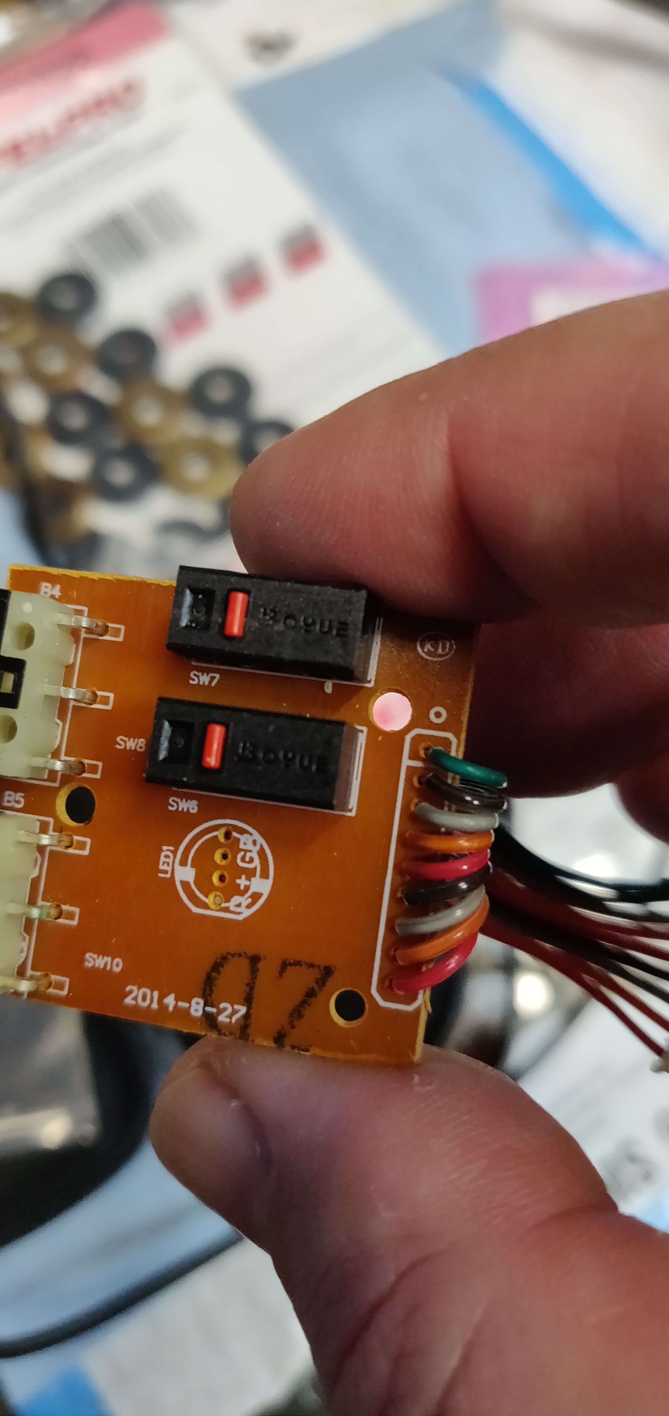
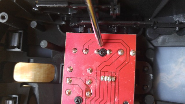
Step 10: Removing the old LEDs.
Each LED on the main board has two pins, and in the hole marked with a + sign, and the other in the hole marked "B". From the top of the main board, firmly grasp one of the two LEDs with a pair of pliers. From the bottom, heat the pins on the LED until the solder melts. Pull the LED from the main board. This about the only time in this build that a little force may be needed. Just use common sense. Repeat this step on the second LED. If you have a desoldering tool, remove the solder from the pin holes that the LEDs came out of. Since I don't have a desoldering tool, I cut the pin off of an LED and used that. I heated the solder and pushed the pin through the hole. Do this a couple of times. When the pin on an LED will easily slide through the hole, you are good.
Step 11: Calculate your resistor value
Go to http://www.ledcalc.com and plug in the numbers for your LEDs. Two LEDs are used in this calculation! I used red LEDs; here are my values.
Supply Voltage: 5 volts
Voltage drop across LED (forward voltage) 2.1 volts
Desired LED current 20ma
How many LEDs connected? 2
After entering all of your values, click on calculate.
Nearest higher rated resistor = 47 ohms
Step 12: Solder the appropriate resistor to ONE of the LEDs.
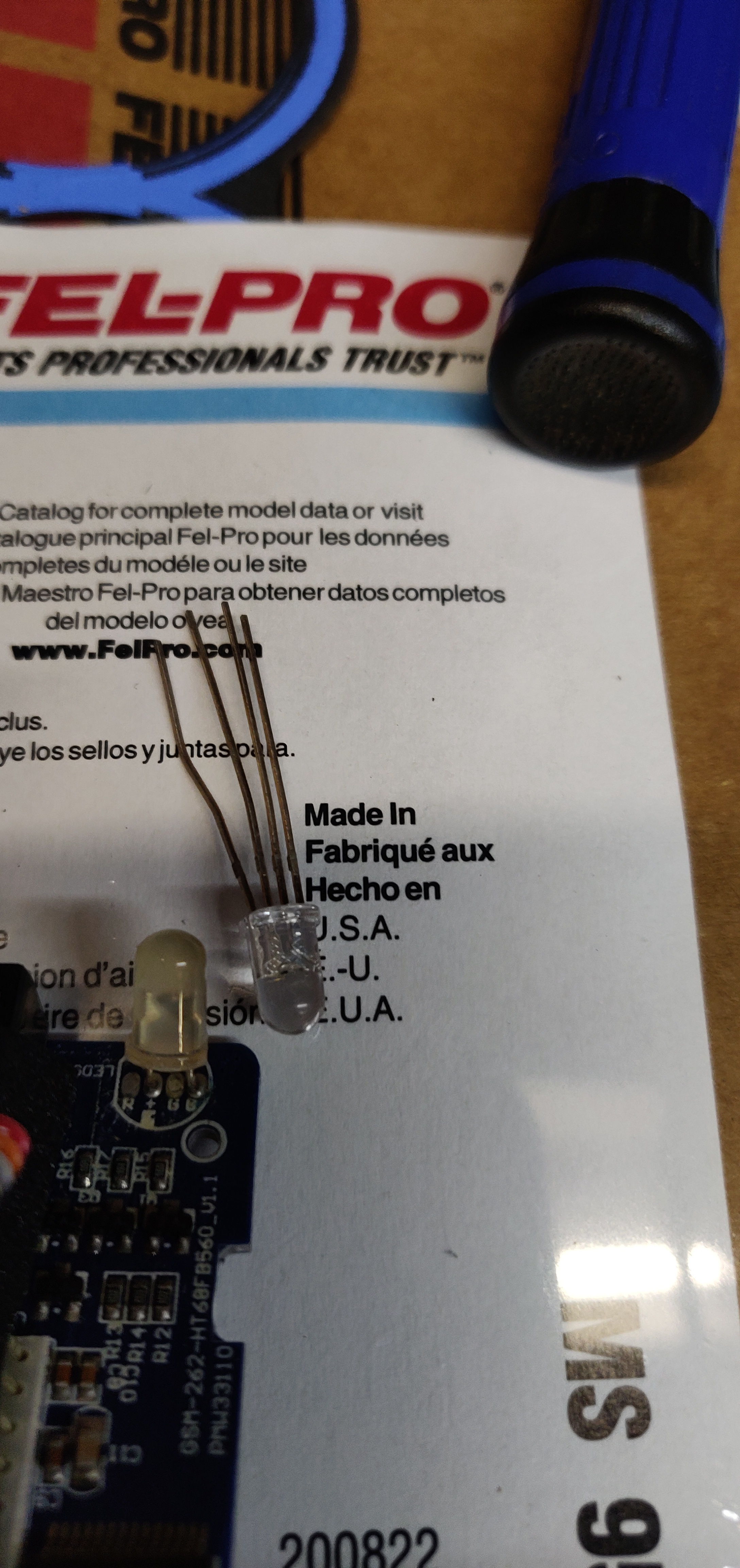
Trim the pins on the resistor and the LED, so that when soldered together they look like this:
This is where the third hand helps. Lay the two pins over top of each other and solder them together.
Step 13: Solder the LED from step 12 into the main circuit board, next to the scroll wheel.
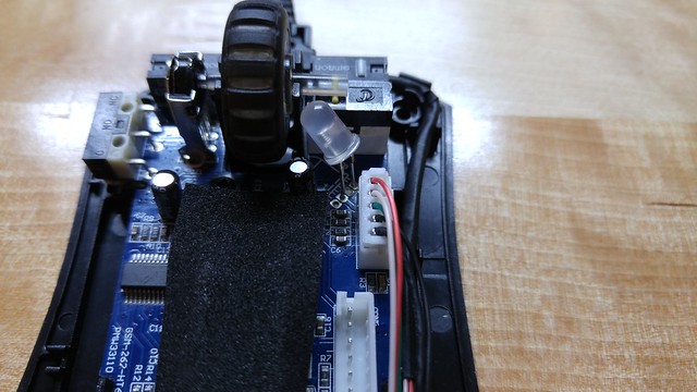
The LED near the scroll wheel needs to be longer than the other one to get the light where we want it. We will use the length added by the resistor to our advantage. Ensuring proper polarity, solder in the LED. Positive on the LED to the "+" terminal on the board and negative on the LED to the "B" terminal on the board. Make sure to leave enough length so that the LED pins can be bent to shine the light into the side of the scroll wheel, as shown:

Trim off the excess length from the LED pins.
Step 14: Solder in the second LED.
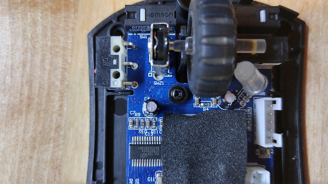
No resistor is required here. The one installed in the previous step will take care of it. Pull this LED allow the way down against the board just like the original. Positive on the LED to the + terminal on the board and negative on the LED to the "B" terminal on the board. Trim off the excess length from the LED pins. It should look like this:
Step 15: Check for solder bridges
Use your DVOM in continuity mode to check for solder bridges between the pins around where we soldered. If you find one, try wiping the area with a cloth, or use a brush. It may just be a piece of loose solder of metal from cutting the LED pins. If you still have a solder bridge, reheat the solder. This will usually break the solder bridge.
Step 16: OPTIONAL. Calculate resistor value for the LED in the DPI board.
This LED has a power feed that is separate from the power going to the other two LEDs on the main board.
That means we need another resistor. Once again, my calculations are for a red LED:
Supply Voltage: 5 volts
Voltage drop across LED (Forward voltage) 2.1 volts
Desired LED current 20ma
How many LEDs connected? 1
Click calculate.
Nearest higher rated resistor = 150 ohms
Step 17: OPTIONAL. Solder the appropriate resistor to the optional LED.
Just like in step 12 above.
Step 18: OPTIONAL. Solder the LED to the DPI board.
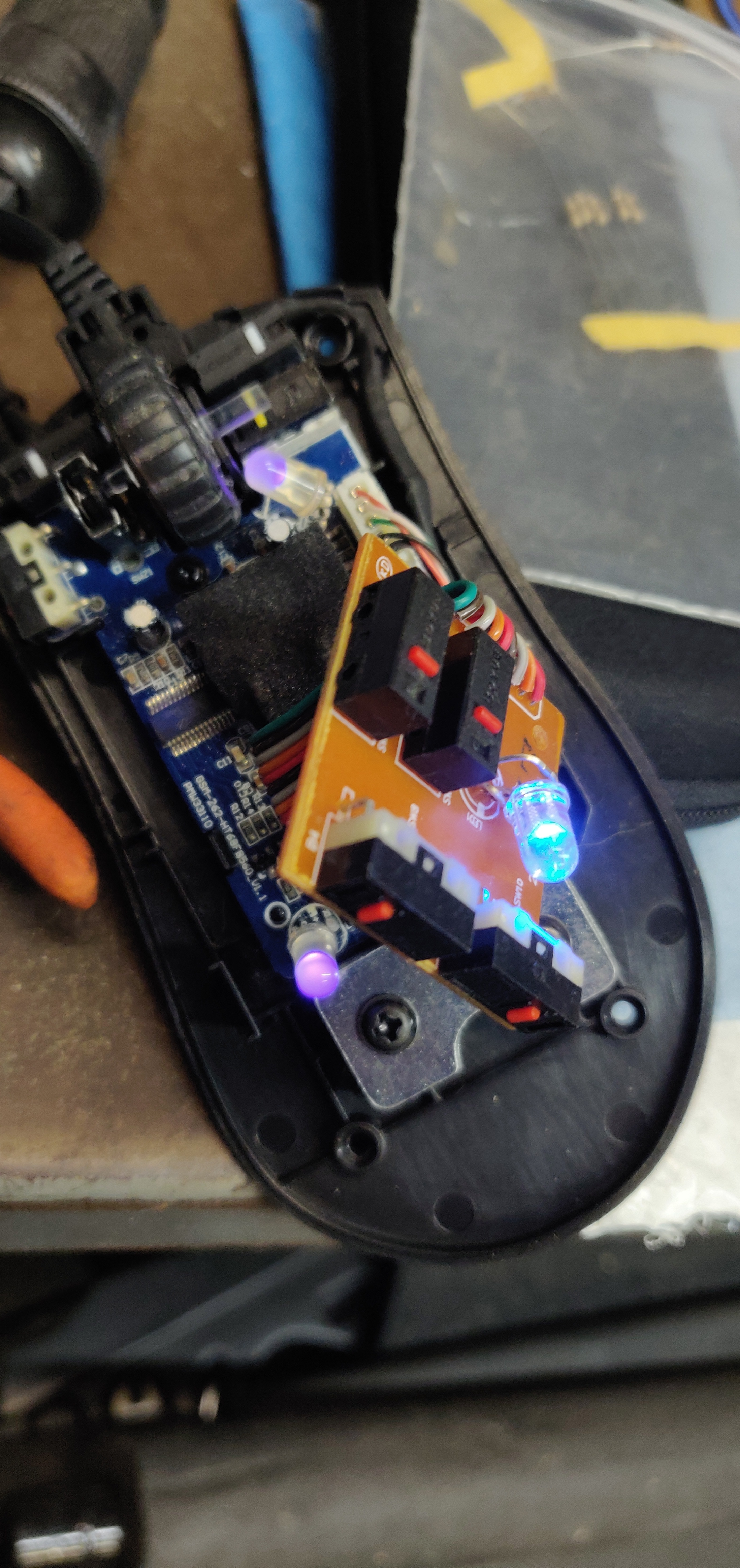
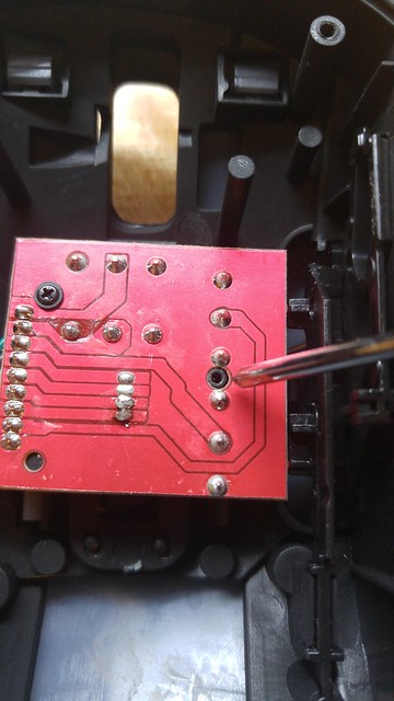
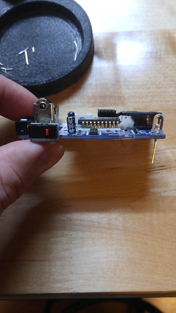
For this LED we are using the "R" terminal instead of the "B" terminal on the DPI board. To get everything to fit back together, this LED must be pulled down fairly close to the DPI board. Ensuring proper polarity, solder in the LED. Positive on the LED to the + terminal on the board and negative on the LED to the "R" terminal on the board. The finished product should look something like this:

Step 19: OPTIONAL. Check for solder bridges on the DPI board.
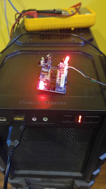
Step 20: Testing.
The moment of truth has arrived. If things go horribly wrong, this is when it's going to happen. If you see any
telltale signs of electronics failure, smoke or popping sounds, unplug the mouse!
If you installed the optional LED, connect the DPI board to the main board via its ribbon cable. Plug the USB cable back into the main board. Plug the USB cable into an available computer. It may take a few seconds, but all of the LEDs should light. Let it run for a few minutes. If your LEDs are still working, chances are your calculations and soldering skills were good. If you blow an LED, an LED doesn't light, or something else goes wrong, you need to double check your connections, resistor values, and LED specs.
Wow, that was a lot! That concludes the Modification section.
Let’s button this thing back up.
Re-Assembly
Step 21: Reinstall the scroll wheel.
Install the hexagon portion of the scroll wheel axle back into the rotary switch on the main board. You may need to turn it back a forth a little to get the hex portions in both pieces to line up.
Step 22: Mate the bottom housing and main circuit board.
Carefully align the main circuit board with the locating pins on the bottom housing. Once everything looks good, push the board into the plastic tabs from step 7. It should go together smoothly. Don't force it. If things aren't going together, check the alignment.

Step 23: Install the screw that holds the main circuit board.
Reverse of step 6
Step 24: OPTIONAL. Reinstall DPI board into top housing.
Reverse of step 9. Look at which way the buttons go on the DPI board vs. the housing, this should help with orientation. Your optional LED should cause no problems with reassembly. If it does, you may need to bend it around a little, or shorten the pins.
NOTE. One of the screws touches two solder terminals on the bottom of the DPI board. This is NOT a problem. These two pins are electrically connected; the screw will make no difference.
Step 25: Plug the DPI board ribbon cable into the main board.
It only goes one way.
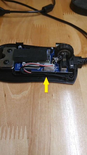
Step 26: Plug in and route the USB cable.
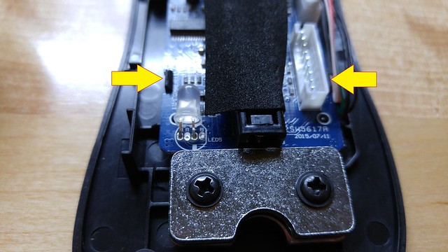
Just like the ribbon cable, it only plugs in one way. The cable routing around the side of the housing is critical. If the cable is not routed correctly, it will be pinched during assembly of the housing. It needs to look like this. The trouble area is highlighted.
Step 27: Mate the housing.
As before, this step should not require anything to be forced. The only resistance that should be felt is from the DPI ribbon cable. If it won't stay together, check the routing of the USB cable. I had this problem when I reassembled mine.
Step 28: Reinstall the four screws holding the housing together.
Step 29: Final testing.
Plug in your newly modified mouse and make sure everything works. Check all of the buttons, and the scroll wheel.

Step 30: Reinstall the friction pads.
My final thoughts.
First, I would like to thank Qain, Wendell, and Eden for their assistance, both direct and indirect, with this project. It has been a struggle, but it’s finally done and posted!
Was this mod worth it? Yes, for me it was. If I had to go back and do it again, I don’t think I would add the optional LED. I really doesn’t add much light, maybe some glow from behind the buttons.
I have been looking for a good project that would allow me to give something back to the community. While it isn't much, it is something. It was rewarding for me personally, and hopefully with this guide, can be rewarding for everyone else that decides to undertake this project.
I will keep this guide as up to date as possible with both new information and corrections to the existing information. Please let me know how your mod goes, if there are any problems with the guide, or any additional information you would like to see included. You can reach me here, on the forums, at TekSyndicate.com. Feel free to put links to this guide anywhere you would like. If you would like to post this guide elsewhere, send me a PM, and we can discuss it. I look forward to hearing from you. Good luck with your mod, and enjoy your new Tek mouse!