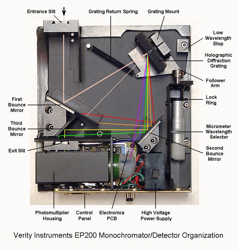
Light comes in through a slit, splits by way of a diffraction grating, and passes through another slit into a photon multiplier tube (PMT). The PMT uses high voltage fields to attract and accelerate incoming photons towards a sensitive detection plate.
A machinist’s micrometer rotates the diffraction grating allowing you to isolate a specific wavelength of light. Each 360° rotation equals 25 nm and is capable of measuring wavelengths from 185 to 925nm.
You can buy the EP200Msd which is a stepper-driven, scanning monochromator on eBay, but it requires a special controller to operate. The goal is to convert the manual version into an Arduino controlled scanner.
There are a couple of builds online, but they are short on details so I’m figuring out a lot of stuff as I go along.
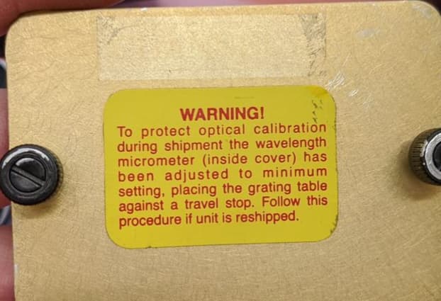
If you buy one, ask the seller to stow the diffraction grating during shipping:
Sadly mine were not and I believe one of them is ~30 nm off. You need a helium neon laser to calibrate them, which I do not have. For relative comparisons of LEDs to natural lighting from the sun, they’ll work fine, but it will be harder to inspect some UV-A and UV-B devices I have.
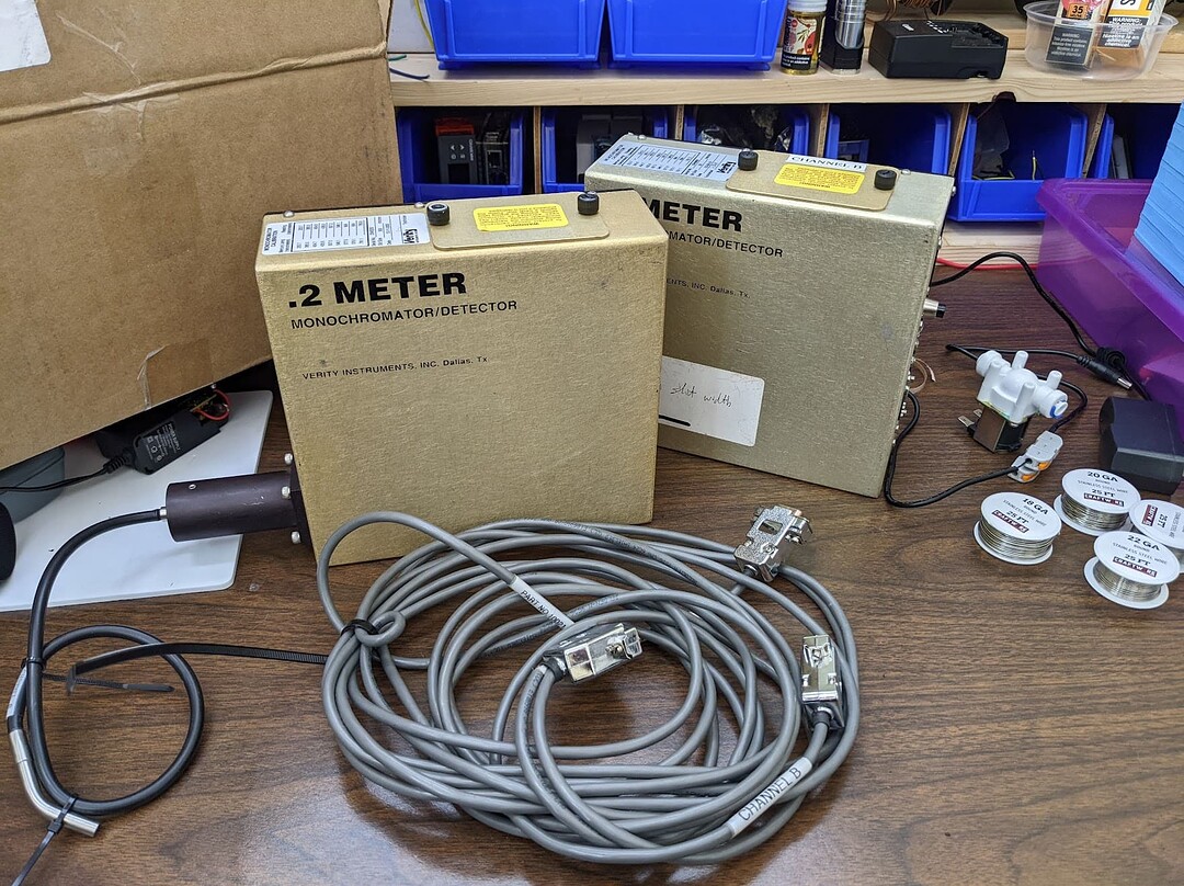
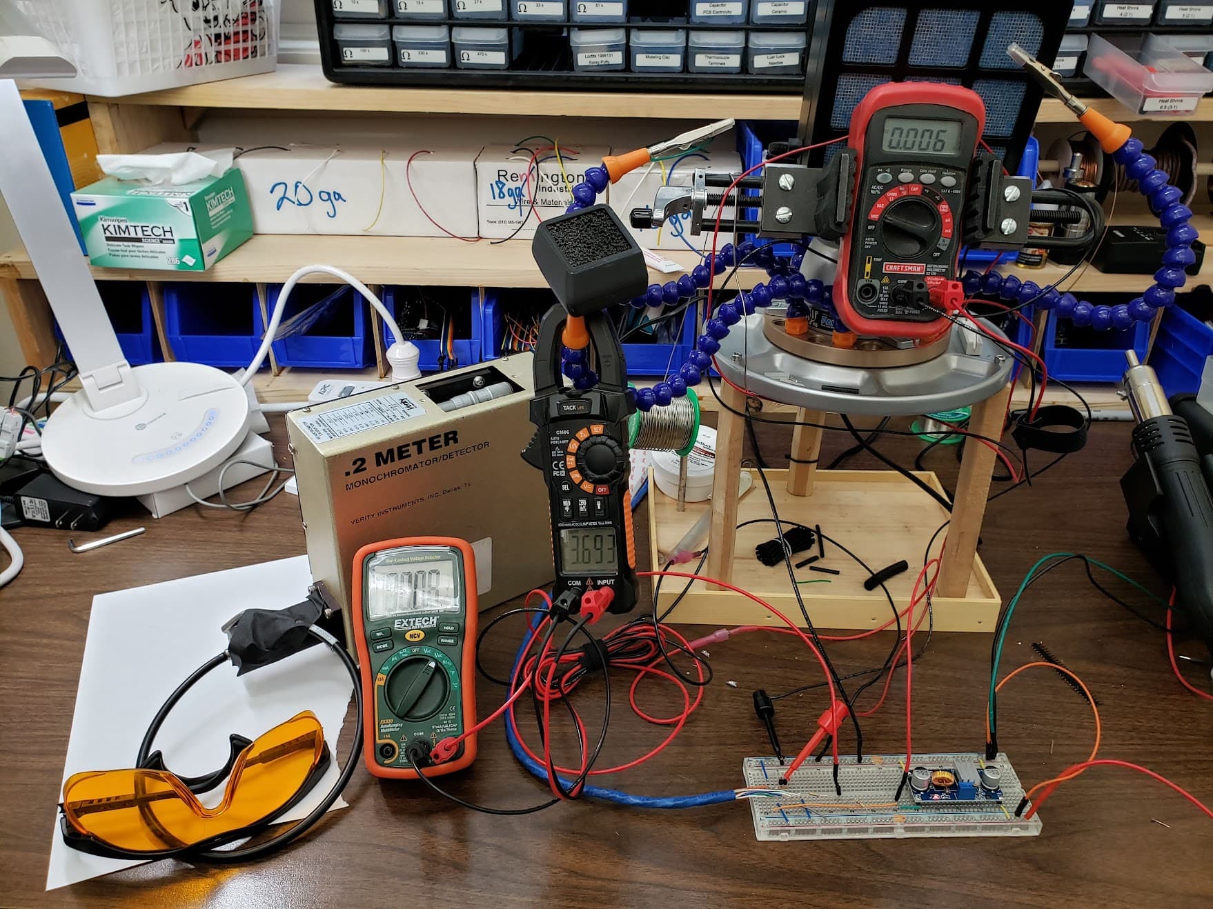
The original Verity controller used a +/- 15V power supply and is connected to these two units using a single DB15 serial cable that splits into two DB9’s.
Step 1 was to make sure they work. I used a bench power supply in series mode for the +/- 15V, monitored the output with some voltmeters, using a CAT 6, 24g wire for the serial cable.
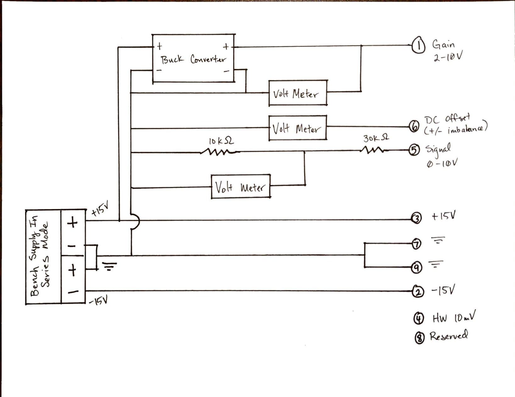
(1) is mislabeled, it should be “Remote High Voltage Programming” instead of “Gain”
Pinout:
Remote High Voltage Programming (HV) - There is a switch inside the unit that determines if the HV is set by a physical pot on the rear of the unit or by this pin. When you set the voltage, it’s sent to a high voltage power supply (EMCO model 6858) which multiplies it by a 100, (i.e. 3V becomes 300V at the PMT).
–15 V
+15 V
Remote High Voltage Monitor - This confirms the actual voltage of the PMT, by taking the voltage output and dividing it by -100 (i.e. 300V at the PMT becomes -3V at the controller). You can adjust the physical HV pot to see if the unit is set for local or remote programming.
Signal output - it says the value can range from 0 to 10V, but I easily read over 10V and up to 15V when the Gain or HV was set too high. I used a 2:1 voltage splitter to keep it under 5V for the eventual Arduino integration.
DC Offset (Zero Voltage) - I think this is how you zero out the PMT remotely, but I zeroed it out with the pot on the back of the device (put tape over the input and adjust until the Signal reads 0.00V).
Circuit Ground Return - The ground
Not Used
Circuit Ground Return - Another ground, which if you forget to wire up will cause the DC Offset to read - 15V
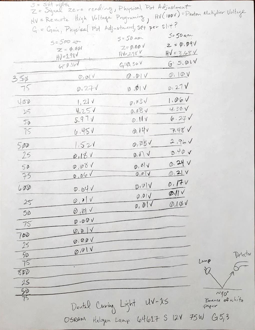
Testing the first unit went smoothly. I set the HV to 3V, put electrical tape over the fiber optic, and used the Zero pot to zero out the Signal. Then I tested a Halogen UV curing unit and a laser pen.
Switching over to the other unit, I couldn’t zero it out. It went from -14 V to -1 V to +0.1V with the slightest change to the Zero pot. I tried the black button, which replaces the pin 5 Signal with the Gain pot setting and saw that Unit 2 had a Gain of 5.00V, while Unit 1 was 0.36V.
I set Unit 2 to 0.36V and was easily able to zero it out. But when testing the same light sources, the values were much lower.
After some head-scratching and checking the optical pathways, I realized that Unit 1 had 500-micron slits and Unit 2 had 50-micron slits. Once I turned the Gain back to 5.00V (and bumped the HV setting), I was able to read values closer to those of Unit 1.
I’m guessing that’s why there isn’t a way to set the Gain remotely. It’s a function of slit size which has to be physically changed. The smaller slit lets you measure narrower bands of light, but adding Gain introduces noise in the PMT.
Now I’m thinking I shouldn’t use a voltage divider with the 50-micron unit. I might be able to keep the Signal under 5V by lowering the Gain and get a cleaner Signal to boot.
I could use some advice from any electrical engineers lurking about.
For the +/- 15V power supply, I’m leaning towards switched (VG1 design) over linear, but only because I don’t know how to balance the load (negative side draws 0.2 A, positive side draws 0.5 A).
The stability of a linear supply will improve the speed at which I can scan, but the toroidal transformer says you shouldn’t use the center tap directly and allow a load imbalance. I’m not sure how big of a deal a 0.3 A imbalance is, or if there is any way to mitigate it.
I’m not understanding the issue with load imbalance in the toroidal transformer here… anyway, what you are calling here “linear” supply is just an ugly drawn rectifier circuit, output is unregulated.
VG1 is nice, it is simple and has also some self-protection built-in, use the first version with the 4 protection diodes D1-D4. A simpler version would be an op-amp with push-pull transistors to get higher output current, but that has no protections… so you’d have to add something and it quickly becomes interesting.
I like VG1 and I’ve ordered parts for it, but I wanted to avoid a switching supply so I’d have the least voltage drop possible. It’s low current, but voltage stability gives you faster, more accurate scanning.
Using the center tap to split the positive and negative circuits, I’m guessing the extra 0.3 amps pulled through the positive coil would turn into heat on the negative coil?
Ok so… sorry for the late reply, I’ve thought about this and I’ve come up with a reasonable answer. Maybe I’m making it harder than it is.
First, the easy parts:
Where do you want to have the least voltage drop (and why do you care)?
Note that with VG1, both the LM317 and LM337 have a ~15V drop each (from I to O), and that the LM337 will get hotter than the LM317 (because it has to sink the extra 0.3A)
VG1 uses a switching power supply to get ±15V and two linear regulators for a virtual ground, the other solution is not regulated at all. So, what do you mean by “stability”? The device you need to supply power to makes a switching supply oscillate?
Now the transformer stuff:
I read this with a different meaning (otherwise it does not make sense to me), it says that you should not think the device as 2 separate transformers (since you have two primary and two secondary windings). The issue here I think is more subtle, a similar discussion I found is here Gearspace.com - View Single Post - 24V regulator question
And maybe clearer here: https://www.coilcraft.com/getmedia/4f23b66a-3dd9-43c9-b867-4c8176755c7b/doc857_Multiple_Applications.pdf (in Voltage / Isolation / Safety).
I can see an issue if you manage to get a high DC voltage between the secondaries, then the isolation between the windings could break down and emit some magic smoke. Here you connect them in series, and there is an example in the datasheet you linked (30Vac). I do not see an issue choosing to use the center tap as ground, it is a common solution to get dual supply voltages.
About the current imbalance, this is what I’ve come up with, as you can see I’ve connected the secondaries in series and used the center tap as ground reference. I’ve split the period of V_2 in T_1 (V_2 > 0) and T_2, used different colors for I_1 and I_2. I explictly omitted capacitors to make this simpler. In our case R_1 < R_2. By KCL to the node G, I_G (ground) is known and flows in the direction of the violet arrow. I’ve drawn there each current flow during T_1 and T_2. In the end, I_G flows in the upper winding during T_1 and in the lower during T_2. This makes sense, and you can go to the extreme removing R_2, making I_2=0. In this case, I_1 flows through the upper winding during T_1 and through the lower one during T_2. This shows that there is no “imbalance” on average (over a single period T), and, if we want to be pedantic, I fail to see a “positive” coil and a “negative” one, you could flip the transformer and nothing would change, during a cycle each coil’s voltage (referenced to ground) is positive then negative, then positive again.
…I hope I’m correct…